Drafting of various geometries using Chamfer, Fillet tool in AutoCad
|
Drafting of various geometries using Chamfer, Fillet tool in AutoCad |
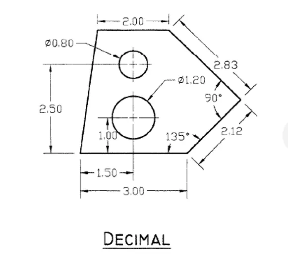
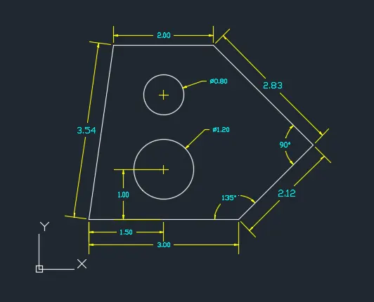
- Aim :- To draft the following geometory by setting the unit of measurement as decimal in AutoCAD Software
- Procedure :-
- Click on AutoCAD application and open this application
- Type QNEW in command bar and enter
- Select default setting as Imperial ( feet and inches )
- In default setting click on use a wizard and in that advance setting and set unit as decimal and precision as 0.00 and press Next
- Set Angle as Decimal Degree and precision as 0 and click next
- Set Angle Measure as EAST and press NEXT
- Set Angle Direction as Counter-Clockwise and press NEXT
- Set Area by providing Length as 5 and Width as 5
- Press finish
- I have kept snap and grid setting off
- Take Line command from command bar
- Specify first point as 1,1
- Specify next point as @2.12<45
- Specify next point as @2.83<135
- Specify next point as @2<180
- Specify next point as 1,1
- And press enter
- Take circle command from command bar
- Specify centre of circle as 2.50,2
- Specify diametr of circle as 1.20
- Press enter
- Take circle command from command bar
- Specify centre of circle as 2.50,3.50
- Specify diametr of circle as 0.80
- Press enter
- Dimensions are used by using dimension command from the command bar
- The drafting of above geometory is done.
- Result :-
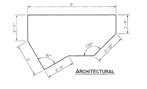
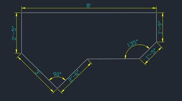
- Aim :- To draft the following geometory by setting the unit of measurement as Architectural in AutoCAD Software
- Procedure :-
- Click on AutoCAD application and open this application
- Type QNEW in command bar and enter
- Select default setting as Imperial ( feet and inches )
- In default setting click on use a wizard and in that advance setting and set unit as Architectural and precision as 0’0” and press Next
- Set Angle as Decimal Degree and precision as 0 and click next
- Set Angle Measure as EAST and press NEXT
- Set Angle Direction as Counter-Clockwise and press NEXT
- Set Area by providing Length as 10’ and Width as 10’
- Press finish
- I have kept snap and grid setting off
- Take a line command from command bar
- Specify first point as 4’,4’
- Specify next point as @1’5’’<45
- Specify next point as @1’9’’<90
- Specify next point as @8’<180
- Specify next point as @2’5’’<270
- Specify next point as @8’0’’<180
- Specify next point as @3’<315
- Specify next point as @2’6’’<45
- And close it
- Dimensions are used by using dimension command from the command bar
- The drafting of above geometory is done.
- Result :-
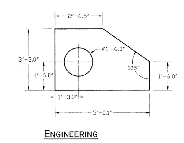
- Aim :- To draft the following geometory by setting the unit of measurement as Engineering in AutoCAD Software
- Procedure :-
- Click on AutoCAD application and open this application
- Type QNEW in command bar and enter
- Select default setting as Imperial ( feet and inches )
- In default setting click on use a wizard and in that advance setting and set unit as Engineering and precision as 0’0.0” and press Next
- Set Angle as Decimal Degree and precision as 0 and click next
- Set Angle Measure as EAST and press NEXT
- Set Angle Direction as Counter-Clockwise and press NEXT
- Set Area by providing Length as 10 and Width as 10
- Press finish
- I have kept snap and grid setting off
- Take a rectangle command from command bar
- Specify first corner as 4,4 and enter
- Specify dimension of rectangle as length 5’0.1” and width as 3’3.0”
- Take chamfer command from command bar
- Select distance
- Specify first chamfer distance as 2’6.0”
- Specify next chamfer distance as 1’9.0”
- Take explode command from the command bar
- Select the object by clicking on the rectangle having chamfered
- Take offset of side having 5’0.1”length
- Mention offset distance as 1’6.0” and take it by keeping curser upside of the length
- Enter
- Take offset of side having 3’3.0”length
- Mention offset distance as 1’3.0” and take it by keeping curser right side of the length
- Intersection point of these both offsets is nothing but the centre of circle
- Take circle command
- Select circle as Centre, diameter type
- Select centre of circle by clickin on the intersection points of offsets
- Specify diameter of circle as 1’6.0”
- Enter
- Take erase command
- And erase the respective offsets
- Dimensions are used by using dimension command from the command bar
- The drafting of above geometory is done.
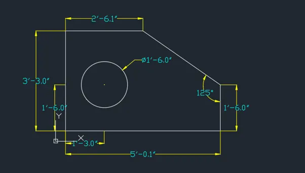
- Result :-
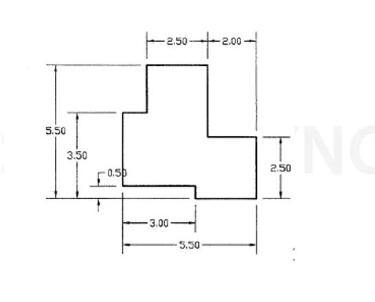
- Aim :- To draft the geometory in AutoCAD Software
- Procedure :-
- Click on AutoCAD application and open this application
- Type QNEW in command bar and enter
- Select default setting as Imperial ( feet and inches )
- In default setting click on use a wizard and in that advance setting and set unit as decimal and precision as 0.00 and press Next
- Set Angle as Decimal Degree and precision as 0 and click next
- Set Angle Measure as EAST and press NEXT
- Set Angle Direction as Counter-Clockwise and press NEXT
- Set Area by providing Length as 10 and Width as 10
- Press finish
- I have kept snap and grid setting off
- Make ortho on
- Take Line command from command bar
- Specify first point as 1,1
- Specify next point as @3.00,0
- Specify next point as @0,-0.50
- Specify next point as @2.50,0
- Specify next point as @0,2.50
- Specify next point as @-2.00,0
- Specify next point as 0,3.00
- Specify next point as @-2.50,0
- Specify next point as @0,-2.00
- Specify next point as @-1.00,0
- Close it
- Dimensions are used by using dimension command from the command bar
- The drafting of above geometory is done.
- Result :-
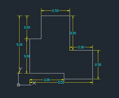
- Aim :- To draft the geometory in AutoCAD Software
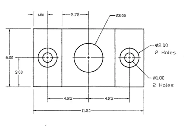
- Procedure :-
- Click on AutoCAD application and open this application
- Type QNEW in command bar and enter
- Select default setting as Imperial ( feet and inches )
- In default setting click on use a wizard and in that advance setting and set unit as decimal and precision as 0.00 and press Next
- Set Angle as Decimal Degree and precision as 0 and click next
- Set Angle Measure as EAST and press NEXT
- Set Angle Direction as Counter-Clockwise and press NEXT
- Set Area by providing Length as 12 and Width as 12
- Press finish
- I have kept snap and grid setting off
- Make ortho on
- Take a rectangle command from command bar
- Specify first corner as 1,1 and enter
- Specify dimension of rectangle as length 11.50 and width as 6.00
- Enter
- Again take a rectangle command from command bar
- Specify first corner as 4,1 and enter
- Specify dimension of rectangle as length 5.50 and width as 6.00
- Enter
- Take a explode command
- Select object by clicking on outer rectangle
- Take offset of side having 11.50 length
- Mention offset distance as 00 and take it by keeping curser upside of the length
- Enter
- Take offset of side having 6.00 length
- Mention offset at a distance as 50 and take it by keeping curser right side of the length ( First Offset )
- Again take offset of side having 6.00 length
- Mention offset at a distance as 75 and take it by keeping curser right side of the length ( Second Offset )
- Again take offset of side having 6.00 length
- Mention offset at a distance as 10.00 and take it by keeping curser right side of the length ( Third Offset )
- Intersection point of these both offsets is nothing but the centre of circles
- Type ddpt in command bar and enter
- Select point style and set point size as 5%
- Select set size related to screen and enter
- Mention point in command bar
- Select a first point as shown below
- Copy that point to another two place just like shown below
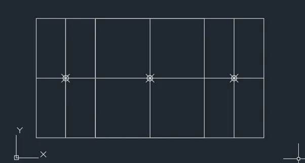
- The above three points are nothing but the centre of circle
- Take circle command and select type as centre, diameter
- Select a first point from above these point
- Mention diameter as 1.00 and enter
- Take circle command and select type as centre, diameter
- Select a same point which is taken above
- Mention diameter as 2.00 and enter
- Take circle command and select type as centre, diameter
- Select a secone point from above these point
- Mention diameter as 3.00 and enter
- Take circle command and select type as centre, diameter
- Select a third point from above these point
- Mention diameter as 1.00 and enter
- Take circle command and select type as centre, diameter
- Select a same point which is taken above
- Mention diameter as 2.00 and enter
- Take erase command
- Erase all the offsets and points which we have drawn for the reference
- Dimensions are used by using dimension command from the command bar
- The drafting of above geometory is done.
- Result :-
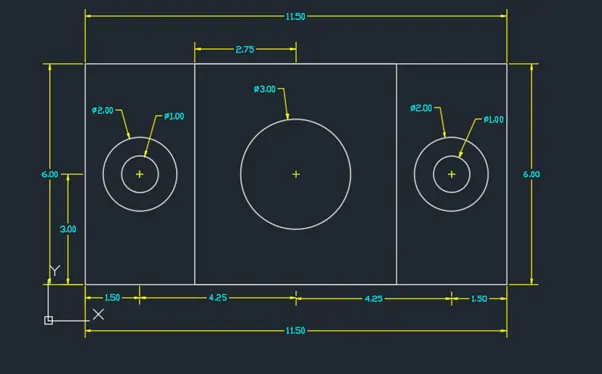
- Aim :- To draft the geometory in AutoCAD Software
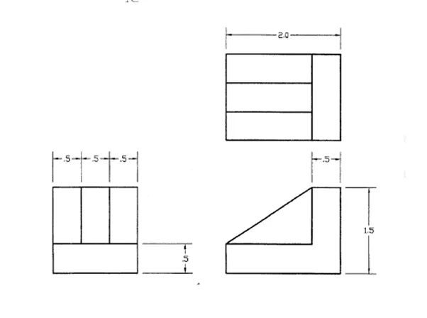
- Procedure :-
- Click on AutoCAD application and open this application
- Type QNEW in command bar and enter
- Select default setting as Imperial ( feet and inches )
- In default setting click on use a wizard and in that advance setting and set unit as decimal and precision as 0.00 and press Next
- Set Angle as Decimal Degree and precision as 0 and click next
- Set Angle Measure as EAST and press NEXT
- Set Angle Direction as Counter-Clockwise and press NEXT
- Set Area by providing Length as 10 and Width as 10
- Press finish
- I have kept snap and grid setting off
- Make ortho on
- Take a rectangle command from command bar
- Specify first corner as 1,1 and enter
- Specify dimension of rectangle as length 1.50 and width as 1.50
- Enter
- Again take a rectangle command from command bar
- Specify first corner as 1,1 and enter
- Specify dimension of rectangle as length 1.50and width as 0.50
- Enter
- Again take a rectangle command from command bar
- Specify first corner as 1.50,1.50 and enter
- Specify dimension of rectangle as length 0.50and width as 1.00
- Enter
- Take construction line from three points as shown below and draw one random line to trim the unwanted construction line as shown below
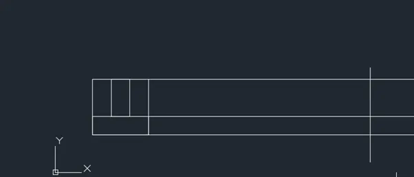
- Trim the unwanted construction line
- Take rectangle command
- Specify its first corner point as 4,1
- Mention its dimension
- Length as 2.0 and width as 1.5
- Take chamfer command
- And click on distance
- Specify first chamfer distance as 1
- Specify next point as 1.5
- Select the object
- Enter
- Draw the construction lines vertically and take any random line which is perpendicular to these construction line to trim the remaining part of construction line
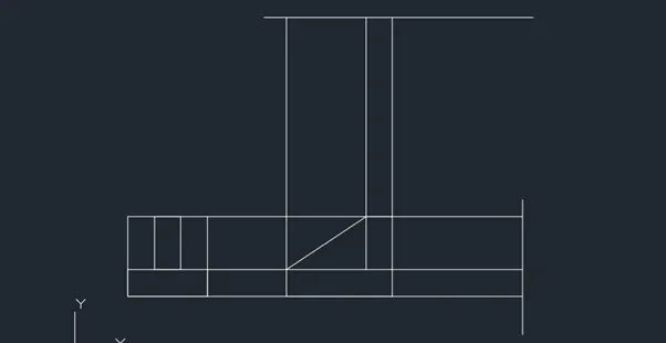
- Take rectangle command
- Specify first corner at 4.0,3.9
- Select dimension
- Specify length as 2.0 and width as 1.50
- Take the explode command
- Select the object as above rectangle
- And take 2 offset of side having 2.0 length one at 0.5 and another offset at 1
- Trim and erase the unwanted lines
- Dimensions are used by using dimension command from the command bar
- The drafting of above geometory is done
- Result :-
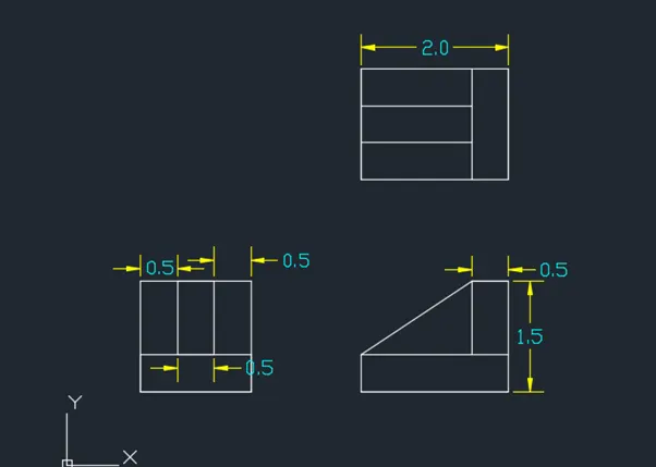
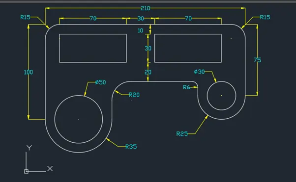
- Aim :- To draw the geometory by using the AutoCAD software
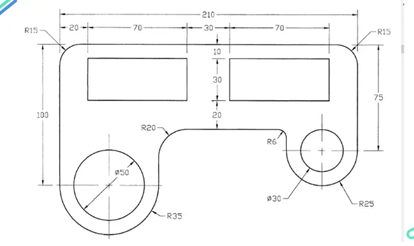
- Procedure :-
- Click on AutoCAD application and open this application
- Type QNEW in command bar and enter
- Select default setting as Imperial ( feet and inches )
- In default setting click on use a wizard and in that advance setting and set unit as decimal and precision as 0 and press Next
- Set Angle as Decimal Degree and precision as 0 and click next
- Set Angle Measure as EAST and press NEXT
- Set Angle Direction as Counter-Clockwise and press NEXT
- Set Area by providing Length as 250 and Width as 150
- Press finish
- I have kept snap and grid setting off
- Make ortho on
- Take a rectangle command from command bar
- Specify first corner as 20,20 and enter
- Specify dimension of rectangle as length 210 and width as 135
- Enter
- Take explode command and select the rectangle
- Take offset command
- Specify offset distance as 35
- Select object as side A and keep curser up side of A and enter
- Take offset command
- Specify offset distance as 35 and select multiple enter
- Select object as side D and keep curser Right side of D and enter
- Give the two offsets
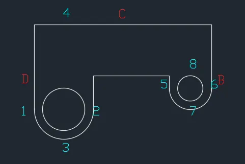
- Take arc command
- Select arc type- Start,End,Radius
- Specify start point by clicking on point 1
- Specify end point by clicking on point 2
- Specify radius as 35 and enter
- The intersection of points 1,2 and 3,4 is nothing but the centre of circle
- Take circle command
- Select circle type- Centre diameter
- Select centre of circle by Click on intersection point
- Mention diameter of circle as 50 and enter
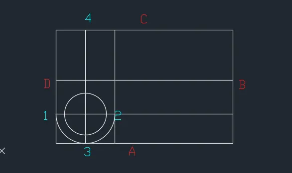
- Take offset command
- Specify offset distance as 25 and select it for multiple
- Select object as side B and keep curser Left side of B
- enter
- Give the two offsets as shown below
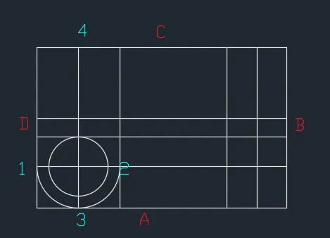
- Select arc type- Start,End,Radius
- Specify start point by clicking on point 5
- Specify end point by clicking on point 6
- Specify radius as 25 and enter
- The intersection of points 5,6 and 7,8 is nothing but the centre of circle
- Take circle command
- Select circle type- Centre diameter
- Select centre of circle by Click on intersection point
- Mention diameter of circle as 30 and enter
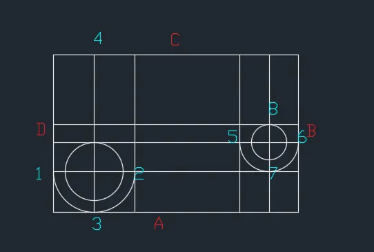
- Trim and erase the unwanted parts
- Take the offset command
- Take the offset of C one at 10 and second offset is at 40 by keeping curser below the side C
- Enter
- Take the offset command
- Take the offset of B one at 25, second offset is at 95, third at 125 and fourth at 195 by keeping curser left side of B
- Enter
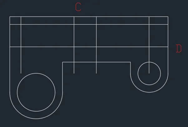
- Trim and erase the unwanted lines
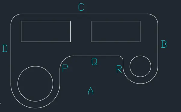
- Take fillet command
- Select multiple
- Select as radius
- Mention radius as 15
- Select object as side C and Side D , Side C and side B
- enter
- Again take fillet command
- Select as radius
- Mention radius as 20
- Select object as side P and Side Q
- enter
- Again take fillet command
- Select as radius
- Mention radius as 6
- Select object as side Q and Side R
- Enter
- Dimensions are used by using dimension command from the command bar
- The drafting of above geometory is done.
- Result :-
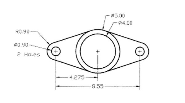
- Aim :- To draw the geometory by using the AutoCAD software
- Procedure :-
- Click on AutoCAD application and open this application
- Type QNEW in command bar and enter
- Select default setting as Imperial ( feet and inches )
- In default setting click on use a wizard and in that advance setting and set unit as decimal and precision as 0.000 and press Next
- Set Angle as Decimal Degree and precision as 0 and click next
- Set Angle Measure as EAST and press NEXT
- Set Angle Direction as Counter-Clockwise and press NEXT
- Set Area by providing Length as 10 and Width as 10
- Press finish
- I have kept snap and grid setting off
- Make ortho on
- Open object snap setting
- Clear all the object snap
- Select only centre, midpoint, endpoint, and tangent object snap as on
- Take a line command
- Specify first point as 1,4
- Specify next point as @8.55,0
- Enter
- Take circle command
- Circle type- Centre, diameter
- Due to object snap of centre it will show the centre of the circle on line after moving curser on line
- Select the midpoint as centre of the circle
- Specify diameter as 4
- Again take take same circle point
- Specify diameter as 5
- Again take circle command
- Circle type- Centre, diameter
- Move the curser towards the one endpoint
- Take one endpoint as centre of circle
- Specify diametr as 0.90
- Take circle command ( Circle type – Centre, radius )
- Take same point as centre of circle
- Specify radius of circle as 0.90
- Again take take same circle point
- Specify diameter as 5
- Again take circle command
- Circle type- Centre, diameter
- Move the curser towards the one endpoint
- Take other endpoint as centre of circle
- Specify diametr as 0.90
- Take circle command ( Circle type – Centre, radius )
- Take same point as centre of circle
- Specify radius of circle as 0.90
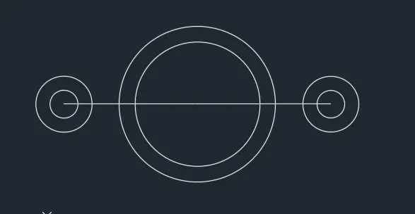
- Take polyline command
- Make ortho off
- For upper left side
- Move the curser towards the outer circle of 1st endpoint
- Due to object snap on it will show tangent symbol, where this symbol is seen click on than point
- Next click on the outer circle of the mid of the line where it will shows the tangent symbol
- Same procedure is repeated for the upper right side, lower left side and lower right side
- It will show us below geometory
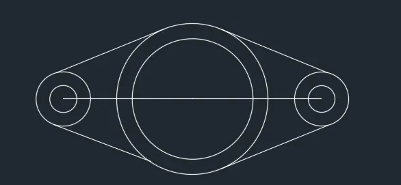
- Erase the line
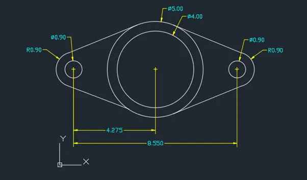
- Trim the unwanted circle to obtain respective geometory
- Dimensions are used by using dimension command from the command bar
- The drafting of above geometory is done.
- Result :-
- Aim :- To draft the geometory by using the AutoCAD software
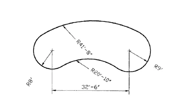
- Procedure :-
- Click on AutoCAD application and open this application
- Type QNEW in command bar and enter
- Select default setting as Imperial ( feet and inches )
- In default setting click on use a wizard and in that advance setting and set unit as Engineering and precision as 0’0” and press Next
- Set Angle as Decimal Degree and precision as 0 and click next
- Set Angle Measure as EAST and press NEXT
- Set Angle Direction as Counter-Clockwise and press NEXT
- Set Area by providing Length as 50’ and Width as 50’
- Press finish
- I have kept snap and grid setting off
- Take line command
- Specify first point as 5’,5’
- Specify next point as @32’6”
- Enter
- Keep object snap on to locate endpoint on line
- Take circle command (Type – Centre, Radius )
- Take centre of circle as one endpoint
- Mention radius of circle as 8’
- Take circle command (Type – Centre, Radius )
- Take centre of circle as another endpoint
- Mention radius of circle as 9’
- Take circle command ( Type – tan,tan,rad)
- Select first tangent as by click on top tangent of left cicle
- Select second tangent as by click on top tangent of right cicle
- Specify radius as 41’8”
- enter
- Take circle command ( Type – tan,tan,rad)
- Select first tangent as by click on bottom tangent of left cicle
- Select second tangent as by click on bottom tangent of right cicle
- Specify radius as 20’10”
- enter
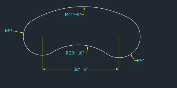
- Trim and erase the unwanted parts to get required geometory
- Dimensions are used by using dimension command from the command bar
- The drafting of above geometory is done.
- Result :-
- Aim :- To draw the geometory by using the AutoCAD software
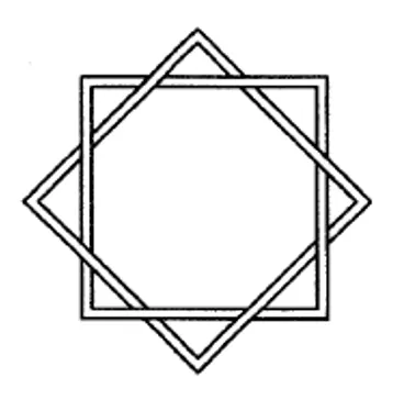
- Procedure :-
- Click on AutoCAD application and open this application
- Type QNEW in command bar and enter
- Select default setting as Imperial ( feet and inches )
- In default setting click on use a wizard and in that advance setting and set unit as decimal and precision as 0.0 and press Next
- Set Angle as Decimal Degree and precision as 0 and click next
- Set Angle Measure as EAST and press NEXT
- Set Angle Direction as Counter-Clockwise and press NEXT
- Set Area by providing Length as 10 and Width as 10
- Press finish
- I have kept snap and grid setting off
- Make ortho on
- Object snap make on
- Take rectangle command
- Specify first corner point at 1,1
- Click on Dimensions
- Specify length as 6 and width as 6 and enter
- Take offset command
- Mention a distance as 0.25
- And select object which is rectangle
- Keeping curser inside enter
- Take rotate command
- Select all the section drawn in sheet
- Select centre of the square as a base point
- Click on copy
- Specify angle of rotation as 45
- enter
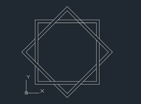
- Trim and erase the unwanted parts to get required geometory
- The drafting of above geometory is done.
- Result :-
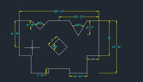
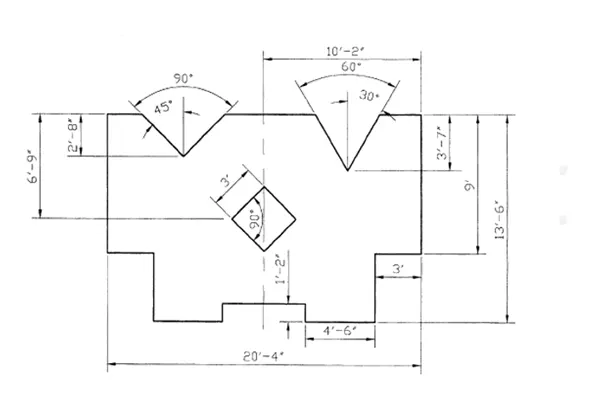
- Aim :- To draft the Geometory by using AutoCADsoftware
- Procedure :-
- Click on AutoCAD application and open this application
- Type QNEW in command bar and enter
- Select default setting as Imperial ( feet and inches )
- In default setting click on use a wizard and in that advance setting and set unit as Engineering and precision as 0’0” and press Next
- Set Angle as Decimal Degree and precision as 0 and click next
- Set Angle Measure as EAST and press NEXT
- Set Angle Direction as Counter-Clockwise and press NEXT
- Set Area by providing Length as 50’ and Width as 50’
- Press finish
- I have kept snap and grid setting off
- Keep ortho on
- Take line command
- Specify first point as 23’3”,2’1’’ ( Point A )
- Specify next point as 1’2” by keeping curser towards the south direction( Point B )
- Specify next point as 4’6” by keeping curser towards the East direction( Point C )
- Specify next point as 4’6” by keeping curser towards the North ( Point D )
- Specify next point as 3’ by keeping curser towards the East direction( Point E )
- Specify next point as 9’ by keeping curser towards the North direction( Point F )
- Specify next point as 3’ by keeping curser towards the West direction ( Point G )
- Specify next point as 7’2” by keeping curser towards the West direction( Point H )
- Specify next point as 7’2” by keeping curser towards the West direction( Point I )
- Specify next point as 3’ by keeping curser towards the West direction( Point J )
- Specify next point as 9’ by keeping curser towards the South direction( Point K )
- Specify next point as 3’ by keeping curser towards the West direction( Point L )
- Specify next point as 4’6” by keeping curser towards the South direction ( Point M )
- Specify next point as 4’6” by keeping curser towards the West direction( Point N )
- Specify next point as 1’2” by keeping curser towards the North direction( Point O )
- Close it ( Point A )
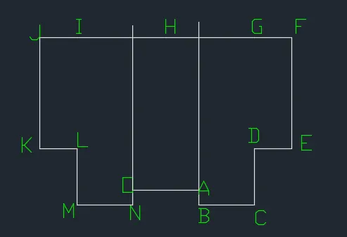
- Take line command
- Specify first point as point A
- Draw the line perpendicular to line JF and enter
- Take line command
- Specify first point as point O
- Draw the line perpendicular to line JF and enter as shown below
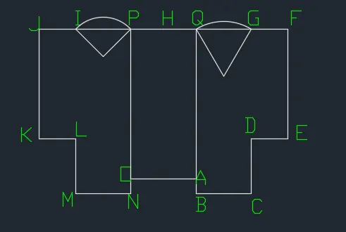
- Take arc command
- Arc type- Start, End, Angle
- Specify start point as by selecting point P
- Specify end point as by selecting point I
- Specify the angle as 90
- Enter
- Take arc command
- Arc type- Start, End, Angle
- Specify start point as by selecting point G
- Specify end point as by selecting point Q
- Specify the angle as 60
- Enter
- Keep ortho snap as ON
- Take a line command and join the
- Join the point P, Point I, Point G, Point Q to their respective centre point of arc as shown below
- Trim the unwanted parts
- Take offset of line FE and JK at 10’9” and 6’2”
- Take polygon command of sides 4
- Specify centre as intersection of these two offsets
- Select circumcircle and mention radius as 1.5’
- It will create polygon of 3’ side each
- Rotate it by 45 by taking baspoint as centre of polygon
- Trim all the unwanted lines
- Dimensions are used by using dimension command from the command bar
- The drafting of above geometory is done.
- Result :-