Creation of geometries by Coordinate system methods using AutoCad
|
Creation of geometries by Coordinate system methods using AutoCad |
Aim :
- To Create the geometries using all the coordinates system methods.
- To use the Line tool to create the geometries and to use circle tool where it is required.
The types of Coordinate systems :
- Absolute Coordinates
- Relative Rectangular Coordinates
- Relative Polar Coordinates
- Direct Distance Entry
1. P-1
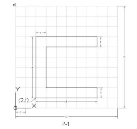
Procedure :
- Absolute coordinates system :
- Click on AutoCAD application and open this application
- Type QNEW in command bar and enter
- Select default setting as Imperial ( feet and inches )
- In default setting click on use a wizard and in that advance setting and set unit as decimal and precision as 0 and press Next
- Set Angle as Decimal Degree and precision as 0 and click next
- Set Angle Measure as EAST and press NEXT
- Set Angle Direction as Counter-Clockwise and press NEXT
- Set Area by providing Length as 10 and Width as 10
- Press finish
- From Home tab click on line
- Then command bar ask us to specify first point
- In front of specify first point press 2,1 ( Point P )
- In front of specify next or [undo] point press 8,1 ( Point Q )
- In front of specify next or [undo] point press 8,2 ( Point R )
- In front of specify next or [undo] point press 3,2 ( Point S )
- In front of specify next or [undo] point press 3,6 ( Point T )
- In front of specify next or [undo] point press 8,6 ( Point U )
- In front of specify next or [undo] point press 8,7 ( Point V )
- In front of specify next or [undo] point press 2,7 ( Point W )
- In front of specify next or [ Close undo] point press Close or press 2,1 ( Point P )
- The Geometry is done.
- Relative Rectangular Coordinates :
- Click on AutoCAD application and open this application
- Type QNEW in command bar and enter
- Select default setting as Imperial ( feet and inches )
- In default setting click on use a wizard and in that advance setting and set unit as decimal and precision as 0 and press Next
- Set Angle as Decimal Degree and precision as 0 and click next
- Set Angle Measure as EAST and press NEXT
- Set Angle Direction as Counter-Clockwise and press NEXT
- Set Area by providing Length as 10 and Width as 10
- Press finish
- From Home tab click on line
- Then command bar ask us to specify first point
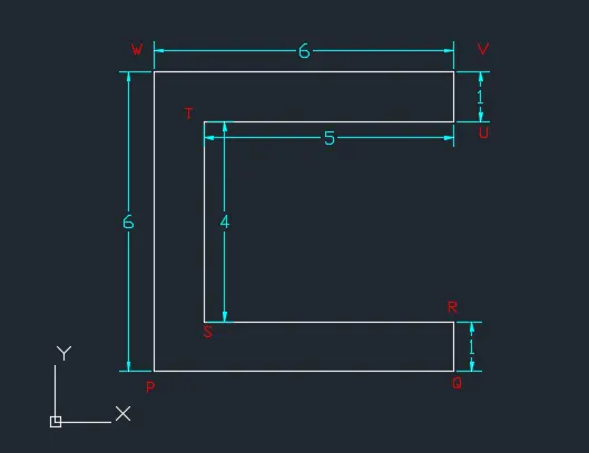
- In front of specify first point press 2,1 ( Point P )
- In front of specify next or [undo] point press @6,0 ( Point Q ) ( Dx = 6, Dy = 0 )
- In front of specify next or [undo] point press @0,1 ( Point R ) ( Dx = 0, Dy = 1 )
- In front of specify next or [undo] point press @-5,0 ( Point S ) ( Dx = 5, Dy = 0 )
- In front of specify next or [undo] point press @0,4 ( Point T ) ( Dx = 0, Dy = 4 )
- In front of specify next or [undo] point press @5,0 ( Point U ) ( Dx = 5, Dy = 0 )
- In front of specify next or [undo] point press @0,1 ( Point V ) ( Dx = 0, Dy = 1 )
- In front of specify next or [undo] point press @-6,0 ( Point W ) ( Dx = 6, Dy = 0 )
- In front of specify next or [ Close undo] point press Close or press @0,-6 ( Point P ) ( Dx = 0, Dy = 6 )
- The Geometry is done.
- Relative Polar Coordinates :
- Click on AutoCAD application and open this application
- Type QNEW in command bar and enter
- Select default setting as Imperial ( feet and inches )
- In default setting click on use a wizard and in that advance setting and set unit as decimal and precision as 0 and press Next
- Set Angle as Decimal Degree and precision as 0 and click next
- Set Angle Measure as EAST and press NEXT
- Set Angle Direction as Counter-Clockwise and press NEXT
- Set Area by providing Length as 10 and Width as 10
- Press finish
- From Home tab click on line
- Then command bar ask us to specify first point
- In front of specify first point press 2,1 ( Point P )
- In front of specify next or [undo] point press @6<0 ( Point Q ) (Towards East )
- In front of specify next or [undo] point press @1<90 ( Point R ) (Towards North )
- In front of specify next or [undo] point press @5<180 ( Point S ) (Towards West )
- In front of specify next or [undo] point press @4<90 ( Point T ) (Towards North )
- In front of specify next or [undo] point press @5<0 ( Point U ) (Towards East )
- In front of specify next or [undo] point press @1<90( Point V ) (Towards North )
- In front of specify next or [undo] point press @6<180 ( Point W ) ( Towards West )
- In front of specify next or [ Close undo] point press Close or press @6<270 ( Point P ) (Towards South )
- The Geometry is done.
- Direct Distance Entry:
- Click on AutoCAD application and open this application
- Type QNEW in command bar and enter
- Select default setting as Imperial ( feet and inches )
- In default setting click on use a wizard and in that advance setting and set unit as decimal and precision as 0 and press Next
- Set Angle as Decimal Degree and precision as 0 and click next
- Set Angle Measure as EAST and press NEXT
- Set Angle Direction as Counter-Clockwise and press NEXT
- Set Area by providing Length as 10 and Width as 10
- Press finish
- From Home tab click on line
- Then command bar ask us to specify first point
- In front of specify first point press 2,1 ( Point P )
- In front of specify next or [undo] point press 6 ( Point Q ) (Keep curser towards East )
- In front of specify next or [undo] point press 1 ( Point R ) (Keep curser towards North )
- In front of specify next or [undo] point press 5 ( Point S ) (Keep curser towards West )
- In front of specify next or [undo] point press 4 ( Point T ) (Keep curser towards North )
- In front of specify next or [undo] point press 5 ( Point U ) (Keep curser towards East )
- In front of specify next or [undo] point press 1( Point V ) (Keep curser towards North )
- In front of specify next or [undo] point press 6 ( Point W ) (Keep curser towards West )
- In front of specify next or [ Close undo] point press Close or press 6( Point P ) (Keep curser towards South )
- The Geometry is done
- Result :
- P-2
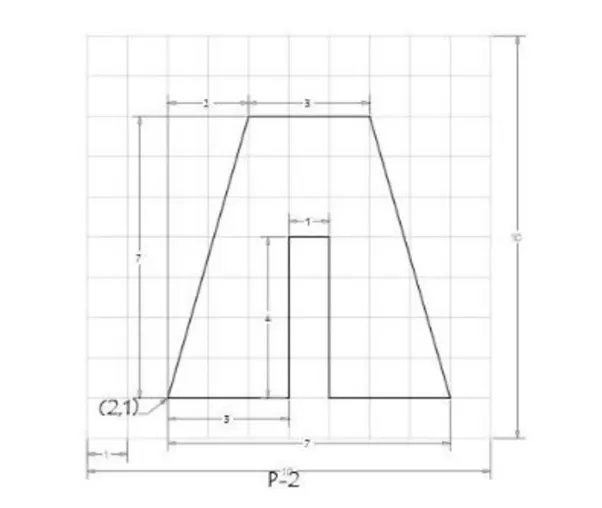
Procedure :
- Absolute coordinates system :
- Click on AutoCAD application and open this application
- Type QNEW in command bar and enter
- Select default setting as Imperial ( feet and inches )
- In default setting click on use a wizard and in that advance setting and set unit as decimal and precision as 0 and press Next
- Set Angle as Decimal Degree and precision as 0 and click next
- Set Angle Measure as EAST and press NEXT
- Set Angle Direction as Counter-Clockwise and press NEXT
- Set Area by providing Length as 10 and Width as 10
- Press finish
- From Home tab click on line
- Then command bar ask us to specify first point
- In front of specify first point press 2,1 ( Point P )
- In front of specify next or [undo] point press 5,1 ( Point Q )
- In front of specify next or [undo] point press 5,5 ( Point R )
- In front of specify next or [undo] point press 6,5 ( Point S )
- In front of specify next or [undo] point press 6,1 ( Point T )
- In front of specify next or [undo] point press 9,1 ( Point U )
- In front of specify next or [undo] point press 7,8 ( Point V )
- In front of specify next or [undo] point press 4,8 ( Point W )
- In front of specify next or [ Close undo] point press Close or press 2,1 ( Point P )
- The Geometry is done.
- Relative Rectangular Coordinates :
- Click on AutoCAD application and open this application
- Type QNEW in command bar and enter
- Select default setting as Imperial ( feet and inches )
- In default setting click on use a wizard and in that advance setting and set unit as decimal and precision as 0 and press Next
- Set Angle as Decimal Degree and precision as 0 and click next
- Set Angle Measure as EAST and press NEXT
- Set Angle Direction as Counter-Clockwise and press NEXT
- Set Area by providing Length as 10 and Width as 10
- Press finish
- From Home tab click on line
- Then command bar ask us to specify first point
- In front of specify first point press 2,1 ( Point P )
- In front of specify next or [undo] point press @3,0 ( Point Q ) ( Dx = 3, Dy = 0 )
- In front of specify next or [undo] point press @0,4 ( Point R ) ( Dx = 0, Dy = 4 )
- In front of specify next or [undo] point press @1,0 ( Point S ) ( Dx = 1, Dy = 0 )
- In front of specify next or [undo] point press @0,-4 ( Point T ) ( Dx = 0, Dy = 4 )
- In front of specify next or [undo] point press @3,0 ( Point U ) ( Dx = 3, Dy = 0 )
- In front of specify next or [undo] point press @-2,7 ( Point V ) ( Dx = 2, Dy = 7 )
- In front of specify next or [undo] point press @-3,0 ( Point W ) ( Dx = 3, Dy = 0 )
- In front of specify next or [ Close undo] point press Close or press @ -2,-7 ( Point P ) ( Dx = 2, Dy = 7 )
- The Geometry is done.
- Relative Polar Coordinates :
- Click on AutoCAD application and open this application
- Type Q+NEW in command bar and enter
- Select default setting as Imperial ( feet and inches )
- In default setting click on use a wizard and in that advance setting and set unit as decimal and precision as 0 and press Next
- Set Angle as Decimal Degree and precision as 0 and click next
- Set Angle Measure as EAST and press NEXT
- Set Angle Direction as Counter-Clockwise and press NEXT
- Set Area by providing Length as 10 and Width as 10
- Press finish
- From Home tab click on line
- Then command bar ask us to specify first point
- In front of specify first point press 2,1 ( Point P )
- In front of specify next or [undo] point press @3<0 ( Point Q ) (Towards East )
- In front of specify next or [undo] point press @4<90 ( Point R ) (Towards North )
- In front of specify next or [undo] point press @1<0 ( Point S ) (Towards East )
- In front of specify next or [undo] point press @4<270 ( Point T ) (Towards South )
- In front of specify next or [undo] point press @3<0 ( Point U ) (Towards East )
- In front of specify next or [undo] point press @7<90( Point A ) (Towards North )
- In front of specify next or [undo] point press @2<180( Point V ) [Join point U and Point V through line and erase line UA and line Av]
- After erasing, again take line command and take start point as V.
- In front of specify next or [undo] point press @3<180 ( Point W ) ( Towards West )
- And from W to P close the geometry through line
- The Geometry is done.
- Direct Distance Entry:
- Click on AutoCAD application and open this application
- Type QNEW in command bar and enter
- Select default setting as Imperial ( feet and inches )
- In default setting click on use a wizard and in that advance setting and set unit as decimal and precision as 0 and press Next
- Set Angle as Decimal Degree and precision as 0 and click next
- Set Angle Measure as EAST and press NEXT
- Set Angle Direction as Counter-Clockwise and press NEXT
- Set Area by providing Length as 10 and Width as 10
- Press finish
- From Home tab click on line
- Then command bar ask us to specify first point
- In front of specify first point press 2,1 ( Point P )
- In front of specify next or [undo] point press 3 ( Point Q ) (Keep curser towards East )
- In front of specify next or [undo] point press 4 ( Point R ) (Keep curser towards North )
- In front of specify next or [undo] point press 1 ( Point S ) (Keep curser towards East )
- In front of specify next or [undo] point press 4 ( Point T ) (Keep curser towards North )
- In front of specify next or [undo] point press 3 ( Point U ) (Keep curser towards East )
- In front of specify next or [undo] point press 7( Point A ) (Keep curser towards North )
- In front of specify next or [undo] point press 2( Point V ) (Keep curser towards West )
- Join Point U and Point V through line and erase line UA and line VA
- Again take line command and start through point V
- In front of specify next or [undo] point press 3 ( Point W ) (Keep curser towards West )
- And from W to P close the geometry through line
- The Geometry is done
- Result :
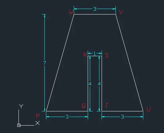
- P-4
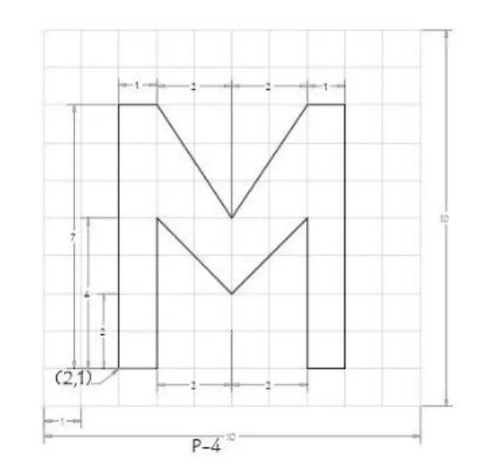
Procedure :
I will choose Absolute coordinate system to create above geometory
- Click on AutoCAD application and open this application
- Type QNEW in command bar and enter
- Select default setting as Imperial ( feet and inches )
- In default setting click on use a wizard and in that advance setting and set unit as decimal and precision as 0 and press Next
- Set Angle as Decimal Degree and precision as 0 and click next
- Set Angle Measure as EAST and press NEXT
- Set Angle Direction as Counter-Clockwise and press NEXT
- Set Area by providing Length as 10 and Width as 10
- Press finish
- From Home tab click on line
- Then command bar ask us to specify first point
- In front of specify first point press 2,1 ( Point A )
- In front of specify next or [undo] point press 3,1 ( Point B )
- In front of specify next or [undo] point press 3,5 ( Point C )
- In front of specify next or [undo] point press 5,3 ( Point D )
- In front of specify next or [undo] point press 7,5 ( Point E )
- In front of specify next or [undo] point press 7,1 ( Point F )
- In front of specify next or [undo] point press 8,1 ( Point G )
- In front of specify next or [undo] point press 8,8 ( Point H )
- In front of specify next or [undo] point press 7,8 ( Point I )
- In front of specify next or [undo] point press 5,5 ( Point J )
- In front of specify next or [undo] point press 3,8 ( Point K )
- In front of specify next or [undo] point press 2,8 ( Point L )
- In front of specify next or [ Close undo] point press Close or press 2,1 ( Point A )
- The Geometry is done.
- Result:-
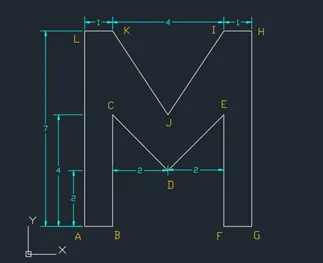
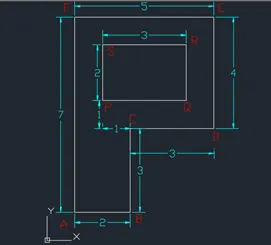
- P-5 :
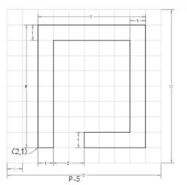
Procedure:
I will choose Relative rectangular coordinate system to create above geometory
- Click on AutoCAD application and open this application
- Type QNEW in command bar and enter
- Select default setting as Imperial ( feet and inches )
- In default setting click on use a wizard and in that advance setting and set unit as decimal and precision as 0 and press Next
- Set Angle as Decimal Degree and precision as 0 and click next
- Set Angle Measure as EAST and press NEXT
- Set Angle Direction as Counter-Clockwise and press NEXT
- Set Area by providing Length as 10 and Width as 10
- Press finish
- From Home tab click on line
- Then command bar ask us to specify first point
- In front of specify first point press 2,1 ( Point A )
- In front of specify next or [undo] point press @1,0 ( Point B ) ( Dx = 1, Dy = 0 )
- In front of specify next or [undo] point press @0,7 ( Point C ) ( Dx = 0, Dy = 7 )
- In front of specify next or [undo] point press @5,0 ( Point D ) ( Dx = 5, Dy = 0 )
- In front of specify next or [undo] point press @0,-6 ( Point E ) ( Dx = 0, Dy = 6 )
- In front of specify next or [undo] point press @-3,0 ( Point F ) ( Dx = 3, Dy = 0 )
- In front of specify next or [undo] point press @0,-1 ( Point G ) ( Dx = 0, Dy = 1 )
- In front of specify next or [undo] point press @4,0 ( Point H ) ( Dx = 4, Dy = 0 )
- In front of specify next or [undo] point press @0,8 ( Point I ) ( Dx = 0, Dy = 8 )
- In front of specify next or [undo] point press @-7,0 ( Point J ) ( Dx = 7, Dy = 0 )
- In front of specify next or [ Close undo] point press Close or press @0,-8 ( Point A ) ( Dx = 0, Dy = 8 )
- The Geometry is done.
- Result :
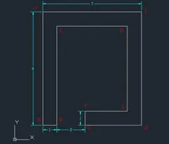
- P-7
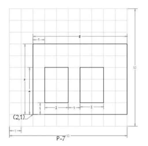
Procedure :
I will choose Relative polar coordinate system to create above geometry.
- Click on AutoCAD application and open this application
- Type QNEW in command bar and enter
- Select default setting as Imperial ( feet and inches )
- In default setting click on use a wizard and in that advance setting and set unit as decimal and precision as 0 and press Next
- Set Angle as Decimal Degree and precision as 0 and click next
- Set Angle Measure as EAST and press NEXT
- Set Angle Direction as Counter-Clockwise and press NEXT
- Set Area by providing Length as 10 and Width as 10
- Press finish
- From Home tab click on line
- Then command bar ask us to specify first point
- In front of specify first point press 2,1 ( Point A )
- In front of specify next or [undo] point press @8<0 ( Point B ) (Towards East )
- In front of specify next or [undo] point press @6<90 ( Point C ) (Towards North )
- In front of specify next or [undo] point press @8<180 ( Point D ) (Towards West )
- In front of specify next or [ Close undo] point press Close
- From Home tab click on line
- Then command bar ask us to specify first point
- In front of specify first point press 3,2 ( Point P )
- In front of specify next or [undo] point press @2<0 ( Point Q ) (Towards East )
- In front of specify next or [undo] point press @3<90 ( Point R ) (Towards North )
- In front of specify next or [undo] point press @2<180( Point S ) (Towards West )
- In front of specify next or [ Close undo] point press Close.
- From Home tab click on line
- Then command bar ask us to specify first point
- In front of specify first point press 6,2 ( Point T )
- In front of specify next or [undo] point press @2<0 ( Point U ) ( Towards East )
- In front of specify next or [undo] point press @3<90 ( Point V ) ( Towards North )
- In front of specify next or [undo] point press @2<180 ( Point W ) ( Towards West )
- In front of specify next or [ Close undo] point press Close
- The Geometry is done.
- Result :
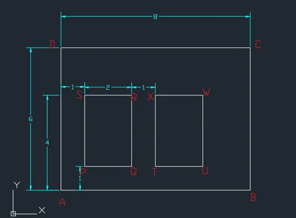
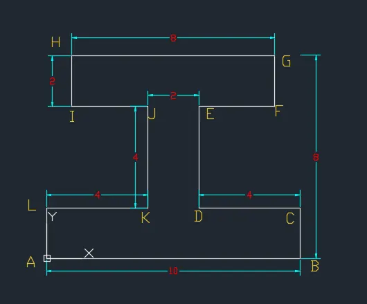
- P-8
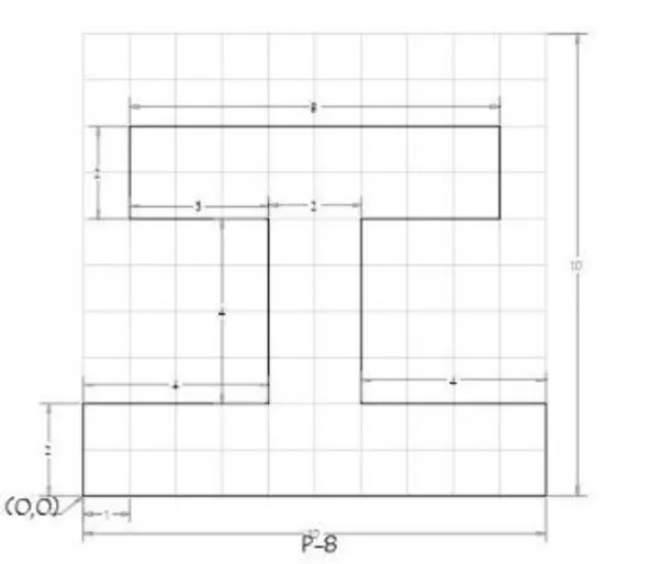
Procedure :
I will choose Direct Distance Entry system to create above geometory.
- Click on AutoCAD application and open this application
- Type QNEW in command bar and enter
- Select default setting as Imperial ( feet and inches )
- In default setting click on use a wizard and in that advance setting and set unit as decimal and precision as 0 and press Next
- Set Angle as Decimal Degree and precision as 0 and click next
- Set Angle Measure as EAST and press NEXT
- Set Angle Direction as Counter-Clockwise and press NEXT
- Set Area by providing Length as 10 and Width as 10
- Press finish
- From Home tab click on line
- Then command bar ask us to specify first point
- In front of specify first point press 0,0 ( Point A )
- In front of specify next or [undo] point press 10 ( Point B ) (Keep curser towards East )
- In front of specify next or [undo] point press 2 ( Point C ) (Keep curser towards North )
- In front of specify next or [undo] point press 4 ( Point D ) (Keep curser towards West )
- In front of specify next or [undo] point press 4 ( Point E ) (Keep curser towards North )
- In front of specify next or [undo] point press 3 ( Point F ) (Keep curser towards East )
- In front of specify next or [undo] point press 2( Point G ) (Keep curser towards North )
- In front of specify next or [undo] point press 8 ( Point H ) (Keep curser towards West )
- In front of specify next or [undo] point press 2 ( Point I ) (Keep curser towards South )
- In front of specify next or [undo] point press 3 ( Point J ) (Keep curser towards East )
- In front of specify next or [undo] point press 4 ( Point K ) (Keep curser towards South )
- In front of specify next or [undo] point press 4 ( Point L ) (Keep curser towards West )
- In front of specify next or [ Close undo] point press Close (Keep curser towards South )
- The Geometry is done
- Result :
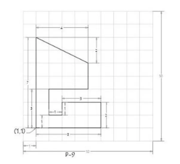
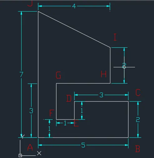
- P-9
Procedure :
I will choose Absolute coordinate system to create above geometory
- Click on AutoCAD application and open this application
- Type QNEW in command bar and enter
- Select default setting as Imperial ( feet and inches )
- In default setting click on use a wizard and in that advance setting and set unit as decimal and precision as 0 and press Next
- Set Angle as Decimal Degree and precision as 0 and click next
- Set Angle Measure as EAST and press NEXT
- Set Angle Direction as Counter-Clockwise and press NEXT
- Set Area by providing Length as 10 and Width as 10
- Press finish
- From Home tab click on line
- Then command bar ask us to specify first point
- In front of specify first point press 1,1 ( Point A )
- In front of specify next or [undo] point press 6,1 ( Point B )
- In front of specify next or [undo] point press 6,3 ( Point C )
- In front of specify next or [undo] point press 3,3 ( Point D )
- In front of specify next or [undo] point press 3,2 ( Point E )
- In front of specify next or [undo] point press 2,2 ( Point F )
- In front of specify next or [undo] point press 2,4 ( Point G )
- In front of specify next or [undo] point press 5,4 ( Point H )
- In front of specify next or [undo] point press 5,6 ( Point I )
- In front of specify next or [undo] point press 1,8 ( Point J )
- In front of specify next or [ Close undo] point press Close or press 1,1 ( Point A )
- The Geometry is done.
- Result :
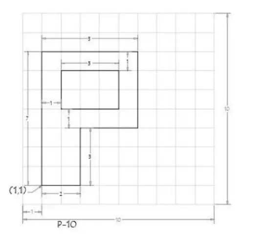
- P-10
Procedure:
I will choose Relative rectangular coordinate system to create above geometory
- Click on AutoCAD application and open this application
- Type QNEW in command bar and enter
- Select default setting as Imperial ( feet and inches )
- In default setting click on use a wizard and in that advance setting and set unit as decimal and precision as 0 and press Next
- Set Angle as Decimal Degree and precision as 0 and click next
- Set Angle Measure as EAST and press NEXT
- Set Angle Direction as Counter-Clockwise and press NEXT
- Set Area by providing Length as 10 and Width as 10
- Press finish
- From Home tab click on line
- Then command bar ask us to specify first point
- In front of specify first point press 1,1 ( Point A )
- In front of specify next or [undo] point press @2,0 ( Point B ) ( Dx = 2, Dy = 0 )
- In front of specify next or [undo] point press @0,3 ( Point C ) ( Dx = 0, Dy = 3 )
- In front of specify next or [undo] point press @3,0 ( Point D ) ( Dx = 3, Dy = 0 )
- In front of specify next or [undo] point press @0,4 ( Point E ) ( Dx = 0, Dy = 4 )
- In front of specify next or [undo] point press @-5,0 ( Point F ) ( Dx = -5, Dy = 0 )
- In front of specify next or [ Close undo] point press Close
- From Home tab click on line
- Then command bar ask us to specify first point
- In front of specify first point press 2,5 ( Point P )
- In front of specify next or [undo] point press @3,0 ( Point Q ) ( Dx = 3, Dy = 0 )
- In front of specify next or [undo] point press @0,2 ( Point R ) ( Dx = 0, Dy = 2 )
- In front of specify next or [undo] point press @-3,0 ( Point S ) ( Dx = 3, Dy = 0 )
- In front of specify next or [ Close undo] point press Close.
- The Geometry is done.
- Result :
- Profile-Wood
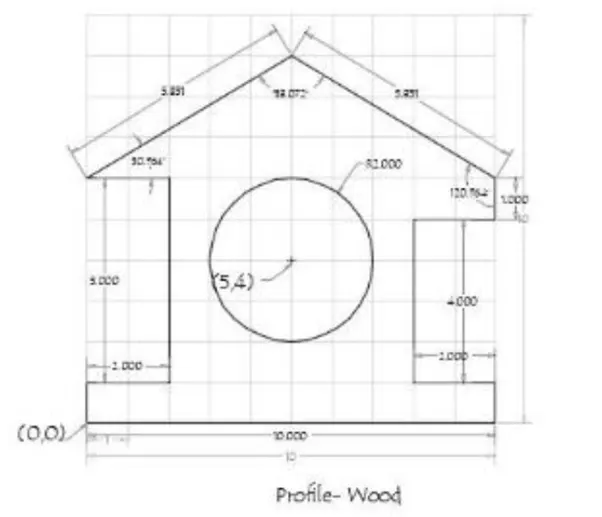
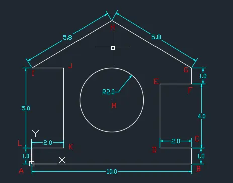
Procedure :
I will choose Absolute coordinate system to create above geometory
- Click on AutoCAD application and open this application
- Type QNEW in command bar and enter
- Select default setting as Imperial ( feet and inches )
- In default setting click on use a wizard and in that advance setting and set unit as decimal and precision as 0.0 and press Next
- Set Angle as Decimal Degree and precision as 0 and click next
- Set Angle Measure as EAST and press NEXT
- Set Angle Direction as Counter-Clockwise and press NEXT
- Set Area by providing Length as 10 and Width as 10
- Press finish
- From Home tab click on line
- Then command bar ask us to specify first point
- In front of specify first point press 0,0 ( Point A )
- In front of specify next or [undo] point press 10,0 ( Point B )
- In front of specify next or [undo] point press 10,1 ( Point C )
- In front of specify next or [undo] point press 8,1 ( Point D )
- In front of specify next or [undo] point press 8,5 ( Point E )
- In front of specify next or [undo] point press 10,5 ( Point F )
- In front of specify next or [undo] point press 10,6 ( Point G )
- In front of specify next or [undo] point press 5,9 ( Point H )
- In front of specify next or [undo] point press 0,6 ( Point I )
- In front of specify next or [undo] point press 2,6 ( Point J )
- In front of specify next or [undo] point press 2,1 ( Point J )
- In front of specify next or [undo] point press 0,1 ( Point J )
- In front of specify next or [ Close undo] point press Close.
- From Home tab click on circle ( centre and radius )
- Then command bar ask us to specify centre point of the circle
- In front of specify centre point of circle press 5,4 ( Point A )
- Now command bar ask us to specify radius of circle
- So in command bar type 2 and enter
- The Geometry is done.
- Result :
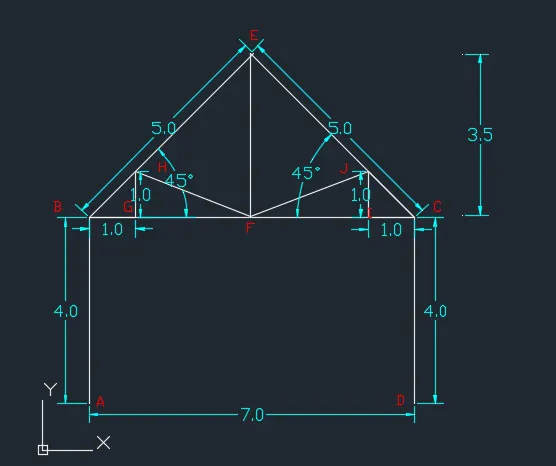
- Queen Post Truss:
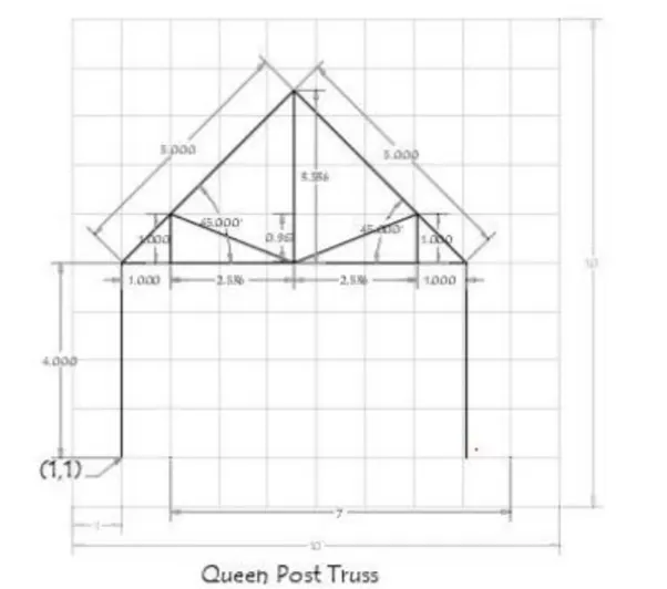
Procedure :
I will choose Relative polar coordinate system to create above geometry.
- Click on AutoCAD application and open this application
- Type QNEW in command bar and enter
- Select default setting as Imperial ( feet and inches )
- In default setting click on use a wizard and in that advance setting and set unit as decimal and precision as 0.0 and press Next
- Set Angle as Decimal Degree and precision as 0 and click next
- Set Angle Measure as EAST and press NEXT
- Set Angle Direction as Counter-Clockwise and press NEXT
- Set Area by providing Length as 10 and Width as 10
- Press finish
- From Home tab click on line
- Then command bar ask us to specify first point
- In front of specify first point press 1,1 ( Point A )
- In front of specify next or [undo] point press @4<90 ( Point B )
- In front of specify next or [undo] point press @7<0 ( Point C )
- In front of specify next or [undo] point press @4<270 ( Point D )
- Press enter
- Again take line command
- Specify first point as 1,5
- In front of specify next or [undo] point press @5<45
- Press enter
- Again take line command
- Specify first point as 8,5
- In front of specify next or [undo] point press @5<135 ( Point E )
- In front of specify next or [undo] point press @3.5<270 ( Point F )
- Press enter
- Again take line command
- Specify first point as 1,5
- In front of specify next or [undo] point press @1<0 ( Point G )
- In front of specify next or [undo] point press @1<90 ( Point H )
- Join line HF
- Press enter
- Again take line command
- Specify first point as 8,5
- In front of specify next or [undo] point press @1<180 ( Point I )
- In front of specify next or [undo] point press @1<90 ( Point J )
- Join line JF
- The Geometry is done.
- Result :
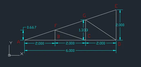
- Mono Pitch
Procedure :
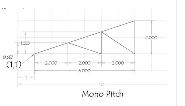
I will choose Absolute coordinate system to create above geometory
- Click on AutoCAD application and open this application
- Type QNEW in command bar and enter
- Select default setting as Imperial ( feet and inches )
- In default setting click on use a wizard and in that advance setting and set unit as decimal and precision as 0.000 and press Next
- Set Angle as Decimal Degree and precision as 0 and click next
- Set Angle Measure as EAST and press NEXT
- Set Angle Direction as Counter-Clockwise and press NEXT
- Set Area by providing Length as 10 and Width as 10
- Press finish
- From Home tab click on line
- Then command bar ask us to specify first point
- In front of specify first point press 1,1 ( Point A )
- In front of specify next or [undo] point press 3,1 ( Point B )
- In front of specify next or [undo] point press 5,1 ( Point C )
- In front of specify next or [undo] point press 7,1 ( Point D )
- In front of specify next or [undo] point press 7,3 ( Point E )
- In front of specify next or [ Close undo] point press Close
- From Home tab click on line
- Then command bar ask us to specify first point
- In front of specify first point press 3,1
- In front of specify next or [undo] point press 3,1.667 ( Point F )
- In front of specify next or [undo] point press 5,1
- In front of specify next or [undo] point press 5,2.333 ( Point G )
- In front of specify next or [undo] point press 7,1
- Press Enter
- The Geometry is done.
- Result :