Creating a Residence Layout, Seating plan, Toilet and Utility room plan using AutoCad
| Creating a Residence Layout, Seating plan, Toilet and Utility room plan using AutoCad |
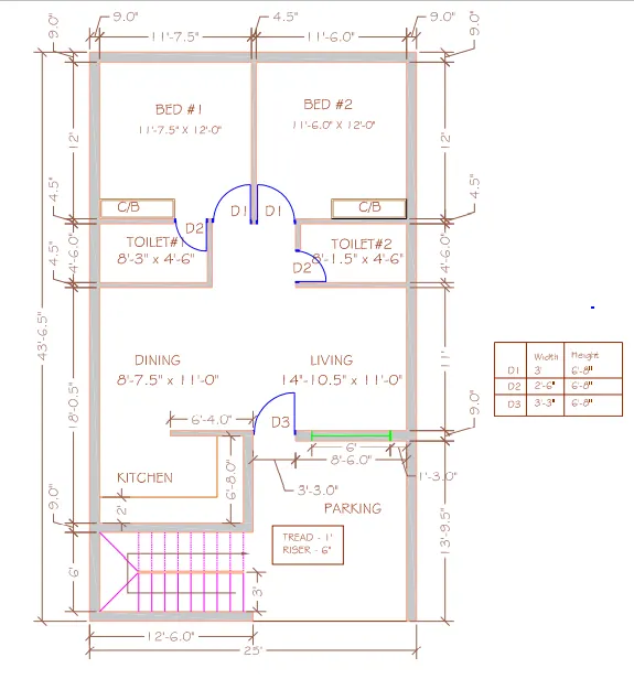
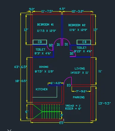
1. Aim : To draw the layout of the residence plan as shown below
- Introduction :
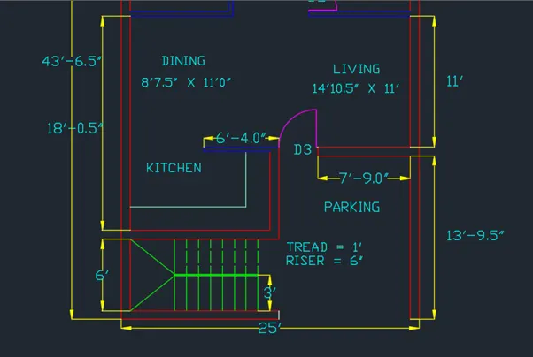
- The above fig is nothing but the residential plan consisting of following units
Two Bedrooms
Two Toilets
A living room
A Kitchen
Dining Room
Parking Unit
Staircase Unit
- Procedure :-
- Click on AutoCAD application and open this application
- Type QNEW in command bar and enter
- Select default setting as Imperial ( feet and inches )
- Press Enter
- I have kept snap and grid setting off
- Keep ortho on
- Press UN and enter and set unit
- Type – Engineering
- Precision – 0’0.0”
- Enter
- Enter limit command in command bar and enter
- Limits specify first left corner > 0,0
- Limit specify upper right corner > 50’,50’
- Enter
- Press Z + enter, A + Enter
- Take Xline command horizontal and vertical
- Trim the negative coordinates
- Take the offsets of both horizontal and vertical lines at 9.0”
- Take the offset of outer xline in 43’6.5” at north direction
- Take the offset of outer xline in 43’6.5” at north direction
- Trim all the unwanted parts
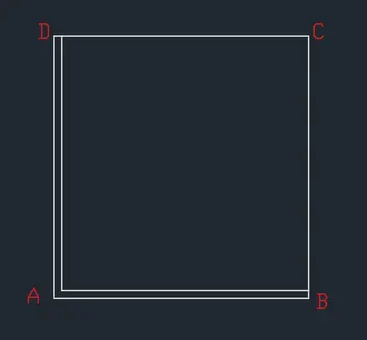
- Take the offset of side DC and side BC at 9.0” inside to show the wall thickness
- Take offset one at 6’ and other at 13’9.5” from the inner side of side AB
- And give offset of both side at 9” and one offset at 4.5”
- Take offset of CD by keeping curser inside at 12’
- And offset of that line at 4.5”
- Again take offset of last offset drawn at 4’6”
- Give offset of side AD at 11’7.5” for the partition of bendroom
- Offest the last offset at 4.5”
- Give offset of side AD at 8’3” and of side BC at 8’1.5” for the Toilet
- Offest the last offsets at 4.5”
- Give offset of side AD at 12’6” for the partition of Kitchen
- Offest the last offset at 9” inside
- Trim the unwanted parts
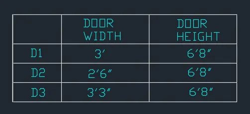
- Leave the places for door according to dimensions provided in schedule i.e D1 = 3’, D2= 2’6”, D3= 3’3”
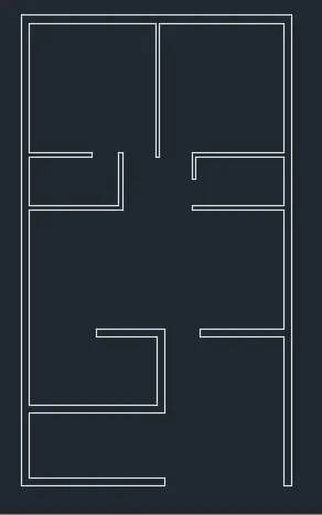
- By using fillet and trim joint all the corner points of the wall as shown below
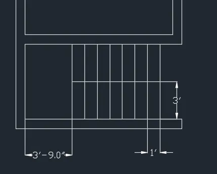
- Give offsets as per dimensions as shown below
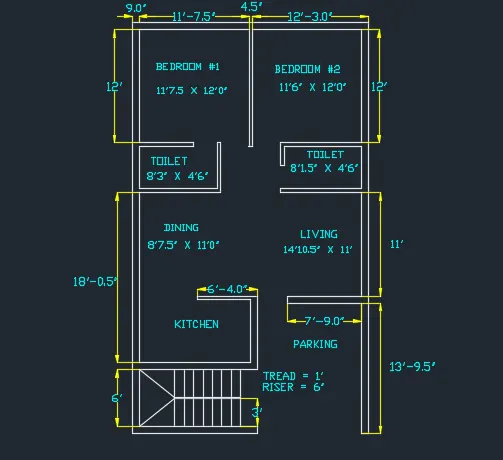
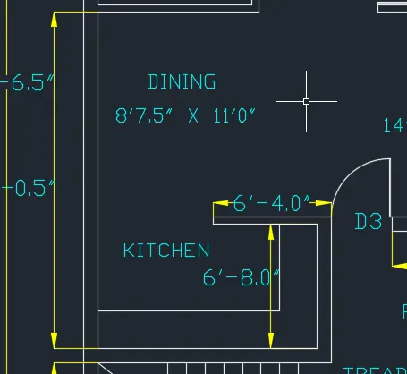
- Give the text and dimensions as per respected drawing as shown below
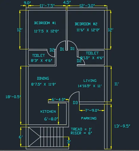
- To draw the bedroom door
- Take a line parallel to wall at distance of 1”
- And take offset of that line at 0.5”
- Take a circle and draw as shown below

- Trim the unwanted part
- Then the D1 is ready
- Similarly draw the other doors i.e D2 and D3 of size 2’6” and 3’3” as shown below
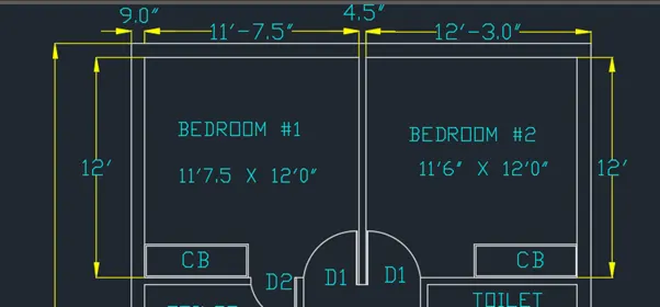
- Cupboard are placed such as shown below by assuming size as 5'7.4" X 1'9.7"
- Kitchen ota is drawn by taking offset at 2’ and unwanted porion is trimmed as shown below
- Click on layer properties
- The following image shows the layes I have choosen
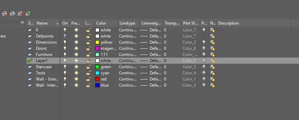
- As per above layer colour select the unit and select its layer
- It will automatically select the colour given by me
- Click on line type
- Load
- Select line type as ACAD_ISO02W100
- And press ok
- And select the stairs which have to shown dotted and select line type as ACAD_ISO2W100 as shown below
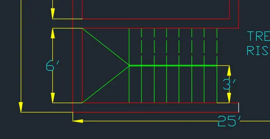
- I have kept all the layers on, all the drawing freez, and all the layers are unlock and colours are given as per above pic.
- Selected all the units as per layer
- The layout of Residence plan is ready
- Result :-
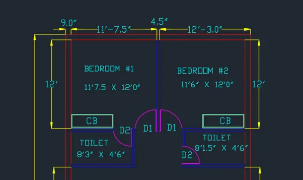
- For Bedrooms and Toilet :
- For Remaining parts :
- For Door Schedule :
- For the total Residential Plan :
2. Outdoor Seating with Canopy :
- Aim :- To Sketch the seating plan for an outdoor canopy by Assuming the dimensions for the seating.
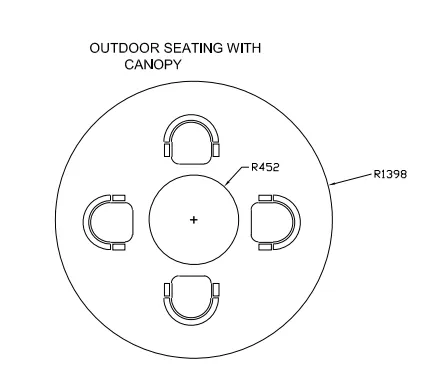
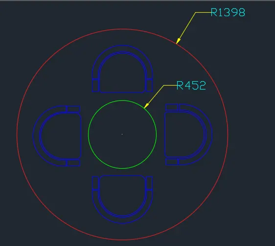
- Introduction : This outdoor seating with canopy contains one round table of radius 452mm and four chars
- Procedure :-
- Click on AutoCAD application and open this application
- Type QNEW in command bar and enter
- Select default setting as Metric
- Press Enter
- I have kept snap and grid setting off
- Keep ortho on
- Press UN and enter and set unit
- Type – Decimal
- Units to inserted content - milimeter
- Precision – 0
- Enter
- Enter limit command in command bar and enter
- Limits specify first left corner > 0,0
- Limit specify upper right corner > 2000,2000
- Enter
- Press Z + enter, A + Enter
- Keep all the object snaps on
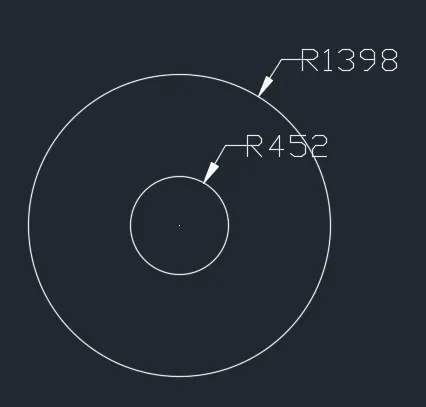
- Take circle command
- Specify centre of the circle as randomly
- Specify radius of that circle = 1398 and enter
- Take again circle command
- Specify centre as the same taken before
- Specify radius as 452 as shown below
- Now, we have to draw chair
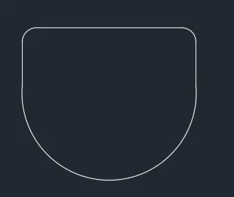
- Take rectangle of size 600 X 200
- Enter
- Take any two corners of rectangle and fillet those corner of radius 50mm
- Take arc command
- Select- Start, End, Direction
- As per convenience arc is drawn by considering remaining two corners
- Trim the middle line in arc and rectangle as shown below
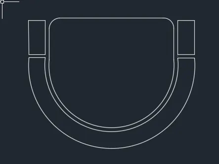
- Take offset command
- Specify offset distance as 20
- Select object as arc
- And give the offset to the last offset at distance 80
- And by using line command close this arcs
- By using rectangle command draw the two rectangle of size 80 X 164 and put these rectangle in a proper position as shown below
- Take copy command
- Take 4 copies of this above chair Out of these three copies
- Out of the three copies
- By taking rotate command and base point as centre of chair
- Rotate one chair at 90
- 2nd at 180
- 3rd rotate at 270
- Move all these chairs and keep in proper position as shown in result
- Result :-
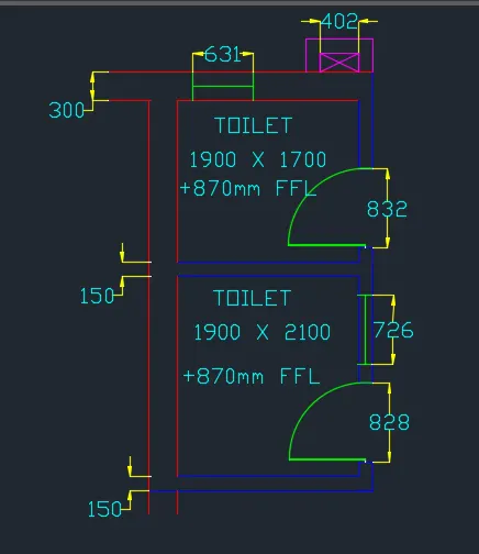
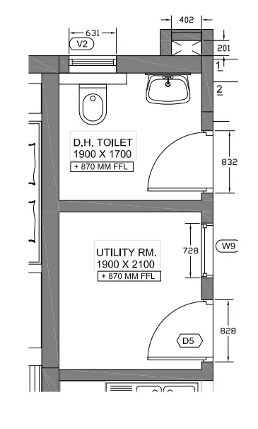
3. Aim :- To Sketch the part plan for the toilet and utilities room
- Introduction :-
- The above plan consist of a toilet and utility room
- The outer wall thickness = 300mm
- The Inner wall thickness = 150mm
- Procedure :-
- Click on AutoCAD application and open this application
- Type QNEW in command bar and enter
- Select default setting as Metric
- Press Enter
- I have kept snap and grid setting off
- Keep ortho on
- Press UN and enter and set unit
- Type – Decimal
- Units to inserted content - milimeter
- Precision – 0
- Enter
- Enter limit command in command bar and enter
- Limits specify first left corner > 0,0
- Limit specify upper right corner > 2500,5000
- Enter
- Press Z + enter, A + Enter
- Take Xline command horizontal and vertical
- Trim the negative coordinates
- Take the offsets of horizontal xline at 300mm inside
- Take the offsets of vertical xline at 150mm inside
- Take the offset of innerr vertical xline in 1900mm and to that offset give offset at 150mm
- Take the offset of innerr vertical xline at a distances of 2100mm, 2250mm, 3950mm, 4250mm, 4451mm, 4751mm as shown below
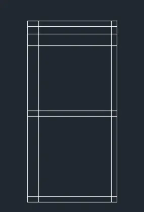
- Provide appropriate offsets to leave space for doors
- For D4 = 832 , D5 = 828
- By using offset command provide proper spacing for windows and ventilator
- For W9 = 728, V = 431
- Also provide duct of size 402 X 201 as shown below
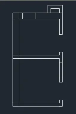
- Provide window line and ventilator line
- By using line and circle command sketch the door as shown below
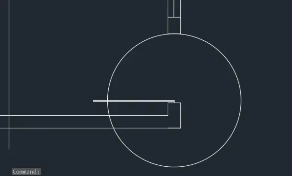
- Trim the unwanted parts
- Similarly draw the toilet door also
- Give the dimensions as shown in fig
- Give the texts as per fig
- Click on layer properties
- The following image shows the layes I have choosen
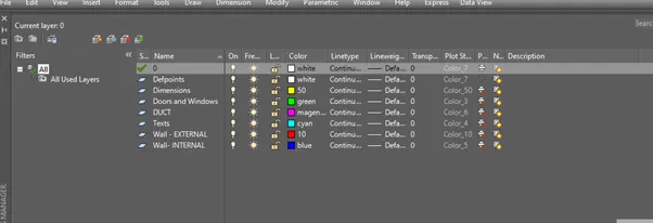
- As per above layer colour select the unit and select its layer
- It will automatically select the colour given by me
- I have kept all the layers on, all the drawing freez, and all the layers are unlock and colours are given as per above pic.
- Selected all the units as per layer
- The plan of toilet and utility room is ready
- Result :-