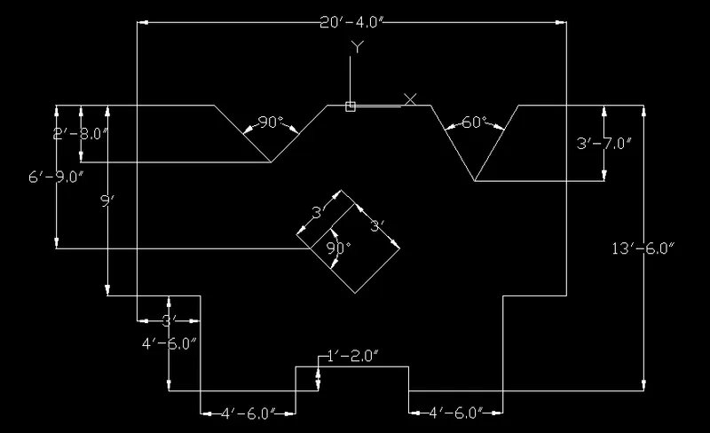
Drafting of various geometries using Chamfer, Fillet tool in AutoCad
Aim: Drafting of various geometries using various tools in Autocad like chamfer, Fillet, Offset, etc.,
Drawing 1:
procedure:
open Autocad
use metric as default settings
template-acadiso.dwt
wizard- quicksetup
units - decimal
area - 10 x10
command units
precision -0.0000
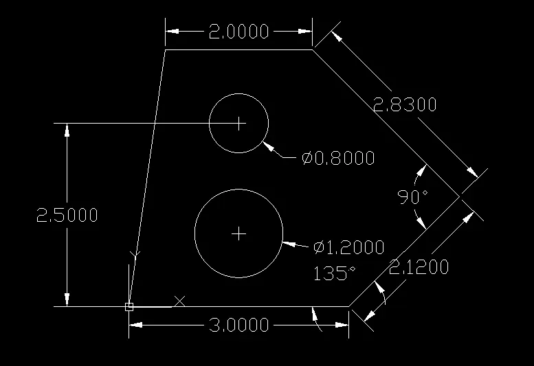
circle command
Draw a circle at 1.5,1 with a diameter of 1.2
line command
start 0,0
@3<0
@2.12<45
@2.83<135
@2<180
close
command- center mark
select the circle to be center marked
select the copy
copy the circle at a distance of 1.5 units center as base point
draw a circle of diameter 0.8 with the center from copied circle
erase the copied circle
Result:
Drawing 2:
procedure:
open Autocad
use imperial as default settings
template-acadiso.dwt
wizard- quicksetup
units - Engineering
area - 10' x10'
command units
precision -0'.0.0"
insertion scale - inches
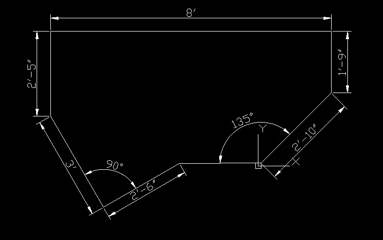
line command
start 1,1
@2'10"<45
@1'9"<90
@8'<180
@2'5"<270
@3"<300
@2'6"<30
close
Result:
Drawing 3:
Procedure:
open Autocad
use imperial as default settings
template-acadiso.dwt
wizard- quicksetup
units - Engineering
area - 10' x10'
command units
precision -0'.0.0"
insertion scale - inches
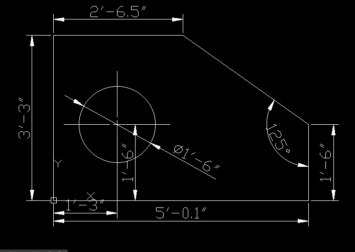
select the circle from ribbon
Draw a circle with the center as 1'3",1'6" and diameter as 1'6" from 0,0
line command
start 0,0
@5'0.1"<0
@1'6"<90
start 0,0
@3'3"<90
@2'6.5"<0
close
Result:
Drawing 4:
Procedure:
open Autocad
use metric as default settings
template-acadiso.dwt
wizard- quicksetup
units - Decimals
area - 10 x10
command units
precision -0.0000
insertion scale - mm
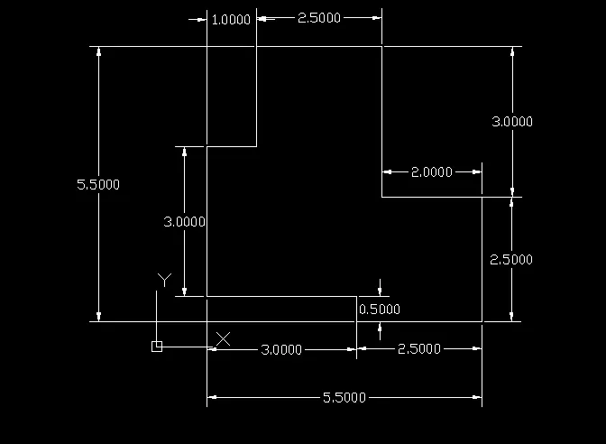
line command
start 1,1
@3<0
@0.5<270
@2.5@0
@2.5@90
@2<180
@3<90
@2.5<180
@2<270
@1<180
@3<270/close
Result:
Drawing 5:
Procedure:
open Autocad
use metric as default settings
template-acadiso.dwt
wizard- quicksetup
units - Decimals
area - 10 x10
command units
precision -0.0000
insertion scale - mm
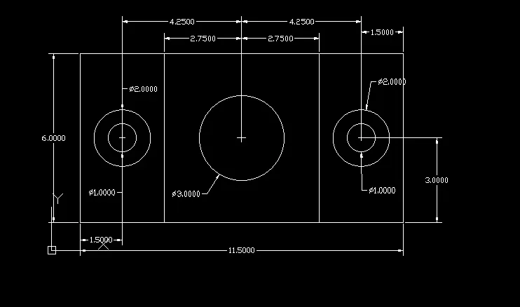
line command
start 1,1
@11.5<0
@6<90
@11.5<180
@6<270/ close
Offset command
offset the 6 unit line at a distance of 1.5 from either side of the rectangle formed
again offset the 6 unit line at a distance of 1.5 from either side
offset the 11.5 line at a distance of 3 from the bottom or top of the rectangle
offset the 6 line at a distance of 5.75 from the left or right side of the rectangle
from the intersection of offset lines draw concentric circles of diameters 2 and 1
copy the concentric circles at a distance of 8.5 with the center as a basepoint
draw a central circle with intersection lines of diameter 3
erase all the unwanted intersection lines
Result:
Drawing 6
Procedure:
open Autocad
use metric as default settings
template-acadiso.dwt
wizard- quicksetup
units - Decimals
area - 10 x10
command units
precision -0.0000
insertion scale - mm
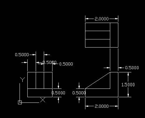
xline command
xline along horizontal and vertical directions
trim command
trim off the left and bottom extensions to make it 90 degrees
offset command
offset the horizontal xline at 0.5 distance
offset the horizontal xline at 1.5 distance from the bottom xline
offset the horizontal xline at 3.5 distance from the bottom xline and continue the offsetting from the same line 3times with a distance of 0.5 intervals
offset the vertical xline at a distance of 0.5 in 3 intervals
offset the vertical xline at a distance of 2 and 4 from the last offsetted xline
trim command
trim off all the unwanted lines connecting
join the corner edges of bottom right view
Result:
Drawing 7
Procedure:
open Autocad
use metric as default settings
template-acadiso.dwt
wizard- quicksetup
units - Decimals
area - 10 x10
command units
precision -0.0
insertion scale - mm
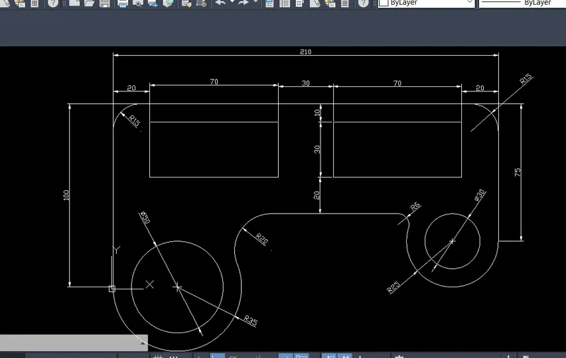
line command
start 1,1
@100<90
@210@0
@75<270
line command
start 1,1
draw a line of 70 facing toward easing
from the end of 70 units line, draw a line of 50 facing toward west since the arcs are of radius 35 and 25
arc command
with a start, end, radius draw an arc of radius 35 on 70 units line with objectsnap On
with a start, end, radius draw an arc of radius 25 on 50 units line
command circle
from the midpoint of 70 line draw a circle of diameter 50 and from the midpoint of 50 line draw a circle of diameter 30
erase command
erase the unwanted lines
offset command
offset the 210 line at a distance of 10 and 100 line at a distance of 20
with the intersection of offsetted line draw a rectangle by selecting it from ribbon with dimensions of length 70 and width of 30
erase the offset lines and select the copy from the ribbon
select the rectangle and copy it a distance of 30 towards the right
offset the 210 line at a distance of 60 towards the south
fillet command
select the 35 radius arc and fillet it with line of the radius of 20
select the 25 radius arc and fillet it with line of the radius of 6
fillet the edges of the geometry with a radius of 15
Result:
Drawing 8
Procedure:
open Autocad
use metric as default settings
template-acadiso.dwt
wizard- quicksetup
units - Decimals
area - 10 x10
command units
precision -0.0000
insertion scale - mm
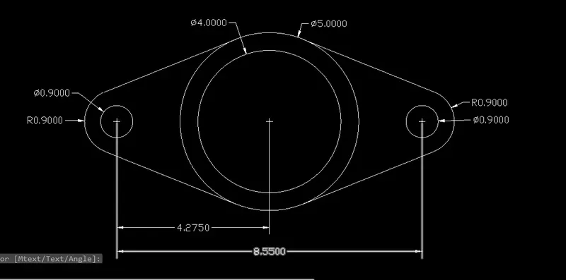
circle command
start 5,5
draw concentric circles of diameter 4 and 5 from 5,5
line command
draw a line of 4.275 from 5,5 on either side
from the endpoint of the line draw concentric circles of diameter 0.9 and radius 0.9 on either side
select the object snap select the tangent
locate the tangents on the circles of diameter 0.9 and connect them
trim of the unwanted lines and arcs
Result:
Drawing 8
Procedure:
open Autocad
use imperial as default settings
template-acadiso.dwt
wizard- quicksetup
units - Engineering
area - 50' x50'
command units
precision -0'.0.0"
insertion scale - inches
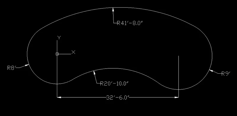
circle command
with origin as center draw a circle of radius 8'
copy the circle at a distance of 32'6"
circle command
select the tangent, tangent, radius draw a circle of radius 20'10" and 41'8" on the bottom and top respectively
Result:
Drawing 10
Procedure:
en Autocad
use metric as default settings
template-acadiso.dwt
wizard- quicksetup
units - Decimals
area - 10 x10
command units
precision -0.0
insertion scale - mm
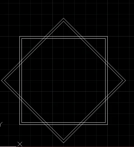
select any point and draw a rectangle of equal length and width
offset command
offset the rectangle slightly higher or lower than that of the rectangle
rotate the rectangle in 45 degrees and copy it
Result:
Drawing 11
Procedure:
open Autocad
use imperial as default settings
template-acadiso.dwt
wizard- quicksetup
units - Engineering
area - 50' x50'
command units
precision -0'.0.0"
insertion scale - inches
line command
start 1,1
@10'2"<180
@9'<270
@3'<0
@4'6"<270
@4'6"<0
@1'2"<90
mirror command
mirror the drawn geometry with 1,1 as a base point
join the bottom with a line
offset command
offset the 20'4" line and 9' line at a distance of 6'9" and 10'2" respectively
rectangle command
draw a rectangle with the intersection as center of dimensions - length 3' and width 3'
rotate the rectangle at an angle of 45 degrees
from 10'2" line with polar tracing On give an angle of 90 degrees and 60 degrees on either side
Result: