Door Trim Panel Developement
Door Trim Panel Development
Abstract
When designing a car’s interior, it is important that passenger should feel the comfort, luxury, and uniqueness throughout the interior. To make it possible the designers design interior trims which includes a dashboard, door trims, roof lining decorations, seating trims etc. The interior trims are the base support for other functional parts that could also support to the overall appearance. These trims are developed by design engineers to process it into practically manufacturable parts using computer aided software. In the following project a door trim panel made up of four individual parts is developed based on given design and put under tests to check its manufacturability. This development and analysis are achieved using CATIA V5 software.
Introduction
A door trim panel is an aesthetic part that fits onto the door inner frame of a car and hides it giving the car interior an aesthetic look. It is usually designed in a way to match with the dashboard to have the sense of uniqueness throughout the interior. They are generally made up of plastics through the process of injection moulding. The most used plastic for door trims is ABS (Acrylonitrile Butadiene Styrene) due to its high rigidity, impact resistance, high dimensional stability, and great surface finishing qualities. The panels provide support to other components such as speakers, buttons, lights, locking mechanism, door arm rest, bottle holder, etc.
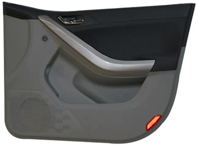
For a door panel’s complete assembly, the parts such as bottle holder, map pocket, arm rest, door lower substrate are attached together with the help of different engineering features which include heat stakes and the panel is mounted onto the door frame with the help of push clips and doghouses. In this project all four parts that are mentioned above are developed, analysed for drafting and assembled to form the required door trim.
Objectives -
- To create Class-B and Class-C surfaces with help of given Class-A and master sections surface for all parts.
- To create closed bodies for solid parts.
- To create engineering features.
- To perform tooling analysis and draft analysis.
- To assemble the parts.
I. Class -A Surface -
In automotive design Class A Surfaces are any set of freeform surfaces of high efficiency and quality. They are created on vehicle's visible surfaces such as body panels, bumper, grill, lights, dash board, door pads etc. From this the production of tools and inspection of finished parts can be carried out. Class A surfacing complements the prototype modelling stage by reducing time and increasing control over design iterations. Designers develop their styling through class A surfaces and create physical surface that end user can see and touch.
II. Class- B Surface -
It is the replica of Class-A which is also the thickened base where all engineering features are attached. The distance of Class-B surface from Class-A surface is decided from the master sections.
III. Class-C Surface -
The surface that joins class-A and Class-B surfaces is called as Class-C surface. It is created at an angle which is equal to draft angle from Class-A Surface.
IV. Engineering Features -
Engineering features are the parts that are assembled onto B-surfaces for attachment and motion restriction purposes. Following are the engineering features designed for this project:
IV.1 Heat Stakes :
Heat stakes are the plastic extruded features that are attached to the parent component. These heat stakes are melted and cooled onto the flanges of other components that are to be fitted with parent component.
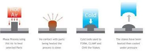
The above image is the cross section of cylindrical heat stakes attached to the base part (black colour) as well as the flange of other part (grey colour). This whole process is called as heat staking or plastic welding.
IV.2 Doghouses :
Doghouses are the engineering features that are used as supporting features. A doghouse is primarily used to avoid sink marks if any thick feature is to be designed directly onto the Class-B Surface. The doghouse design is such that it increases the height for other feature to be attached with also providing the strength needed for that feature to perform effectively. The small cut-out of certain heigh at the bottom of the doghouse avoids sink mark. This also helps if any taller feature is to be designed onto Class-B surface. Following are the design rules for a doghouse designing:
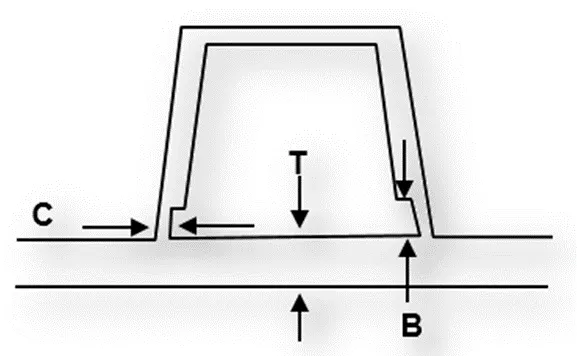
In the above image, T is the part wall thickness, B is the height for the cut-out avoiding sink marks which is in between 3 mm to 6 mm and C is the thickness of the cut-out which is 40% of the wall thickness. The draft angle for the doghouse surfaces is minimum 1.5 degrees.
Iv.3 Ribs :
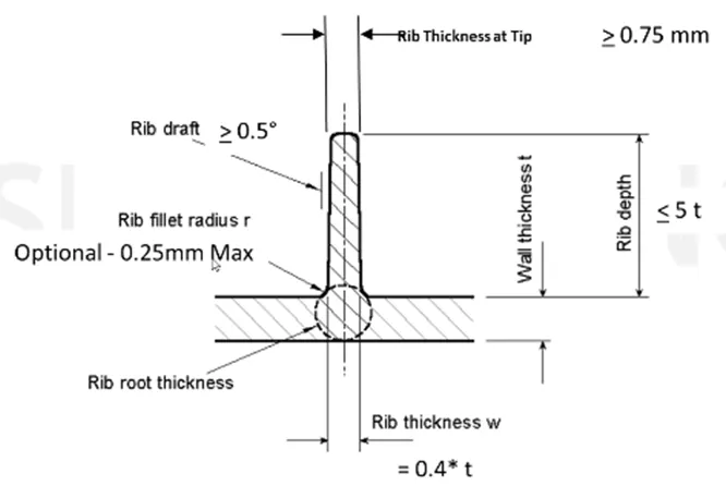
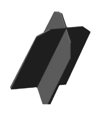
Ribs are rectangular extruded features having different purposes. It can be used as support for other features eliminating the need for that other feature to have increased thickness. It also acts as a two-way locator. It can provide alignment for mating parts. Following are the design rules for rib design:
IV.4 Locators :
Locators are the features which restricts parts motion in all degrees. A two-way locator is used to restrict the two degrees of freedom whereas a four-way locator is used to restrict four degrees of freedom.
IV.5 Push Clips :
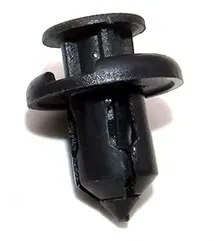
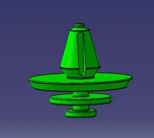
It is plastic component made up of polyamides (nylons) which helps in mounting the parts onto main frame. It aids in easy fittings as well as restricts the translation motion of the part. In this project a push clip is provided which is assembled onto doghouse.
V. Tooling axis -
A tooling axis/ tooling direction is the direction in which core side and the cavity side of the mould are pulled apart from each other. Generally, tooling direction is decided by the geometry of the component design. Deciding the tooling axis to create maximum portion of the part is essential for the manufacturer of the mould as it will affect the cost of the manufacturing process and the product directly.
VI. Draft Analysis –
It is a method checking the draft angles of the part in order to decide whether the CAD part is manufacturable or not. In a mould, the material inserted tends to stick to its surface after cooling and makes it difficult for ejection of the created part. If the mould has straight 90 degrees angle from the base then it will be almost impossible to eject the part from the mould which in turn could damage the mould as well. To ease this process the part will have small draft angles at every area. For sheet metal components the minimum draft angle is 7 degrees and for plastic components it is minimum 3 degrees.
Methodology
Following is the step-by-step process followed for the creation of each part:
- Checking Class-A surface for patches.
- Creation of the tooling axis in the required direction.
- Creation of Class-B surface with the help of master sections. (Here the thickness provided with master section is 2.5 mm).
- Creation of Class-C Surface.
- Creation of Final closed surface.
- Solid modelling using close surface command.
- Creation of B-side engineering features (Doghouses, heat stakes, four-way locators).
- Running draft analysis.
- Providing material (plastic) to parts.
- Assembling the parts.
Pictures of the parts according to above the methodology-
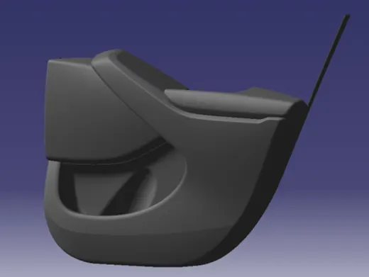
A. Door Arm-Rest
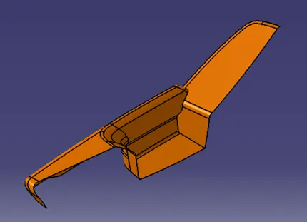
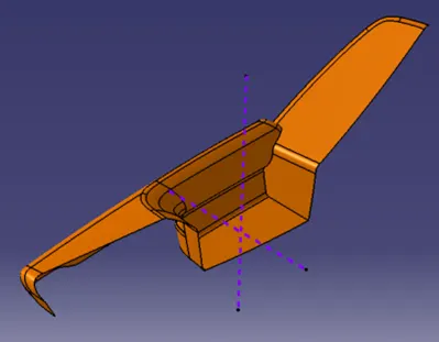
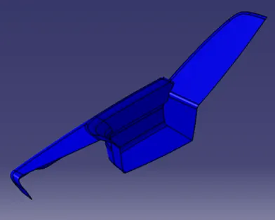
(Class-A Surface) (Tooling Axis) (Class-B Surface)
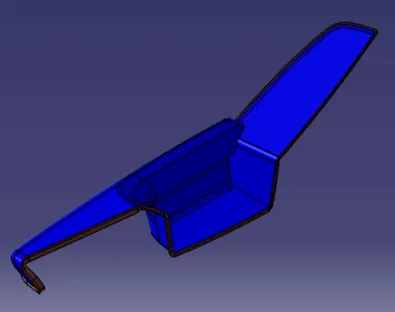
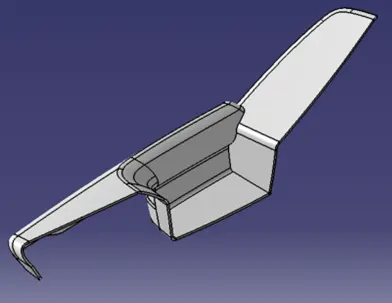
(Class-C Surface) (Solid Model)
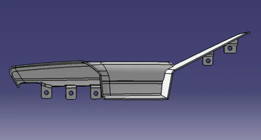
(Flange design for heat stakes)
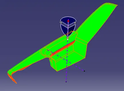
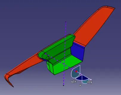
(Class-A Surface Draft Analysis through main tooling axis) (Class-A Surface Draft Analysis through side tooling axis)
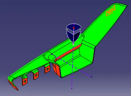
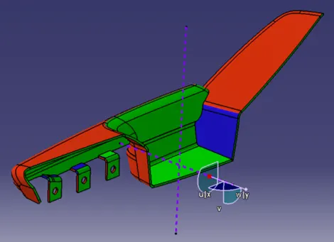
(Final Part Draft Analysis through main tooling axis) (Final Part Draft Analysis through side tooling axis)
B. Map Pocket
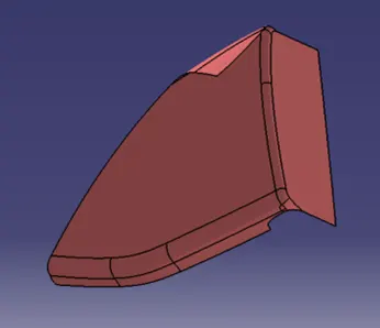
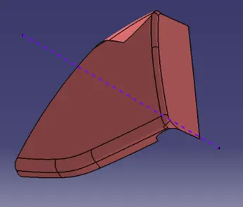
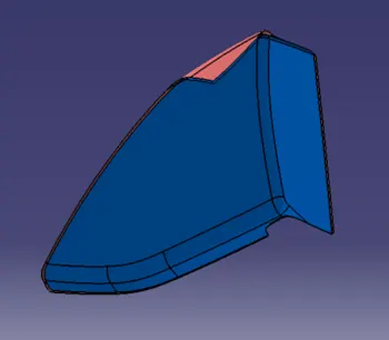
(Class-A Surface) (Tooling Axis) (Class-B Surface)
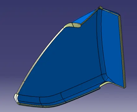
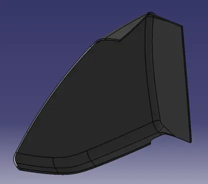
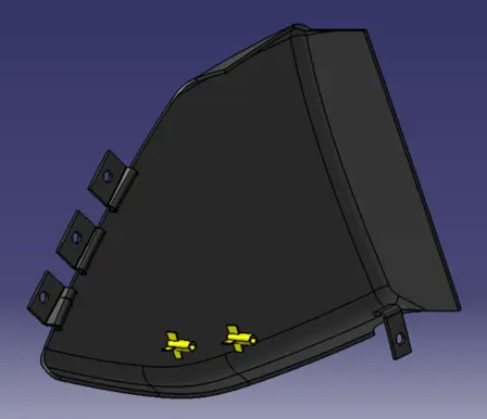
(Class-C Surface) (Solid Model) (Flanges and engineering features)
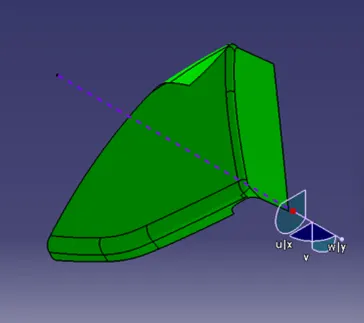
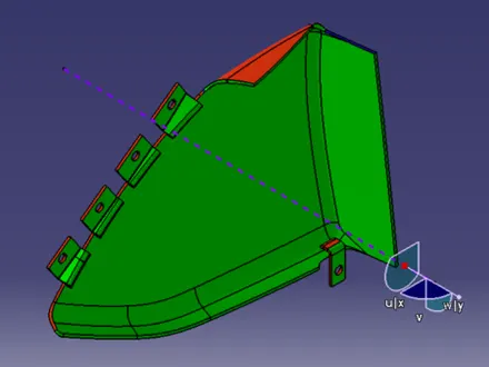
(Class-A Surface Draft Analysis) (Final Part Draft Analysis)
C. Bottle Holder
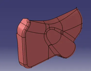
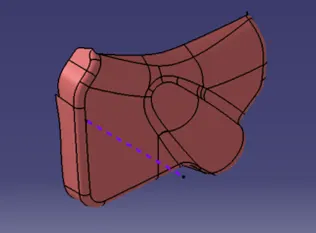
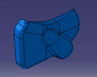
(Class-A Surface) (Tooling Axis) (Class-B Surface)
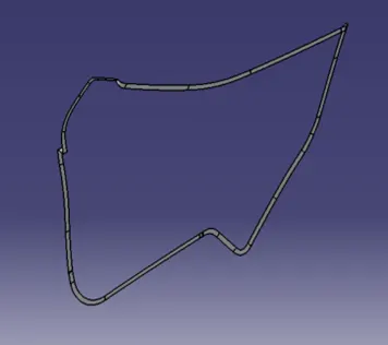
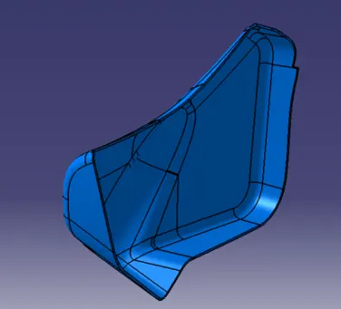
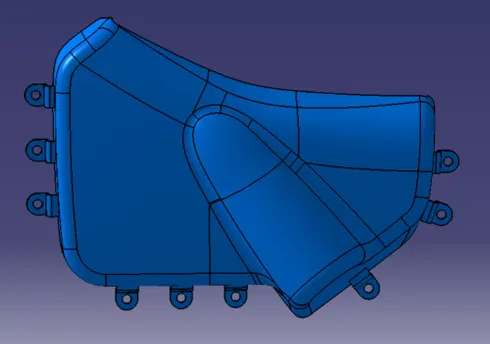
(Class-C Surface) (Solid Model) (Flanges)
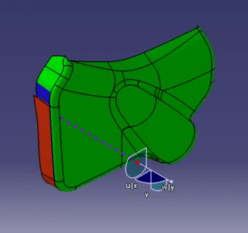
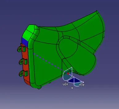
(Class-A Surface Draft Analysis) (Final Part Draft Analysis)
D. Door lower substrate
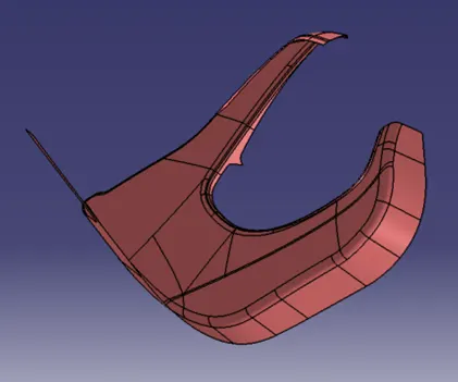
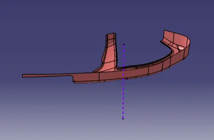
(Class-A Surface) (Tooling Axis)
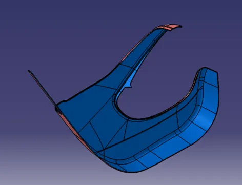
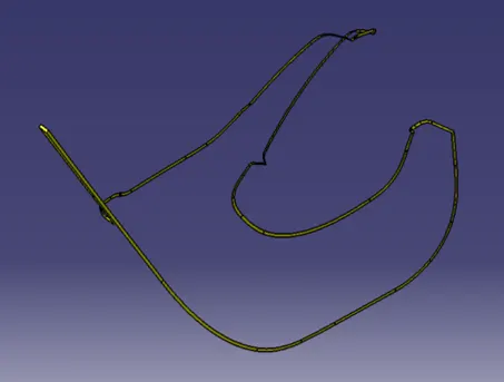
(Class-B Surface) (Class-C Surface)
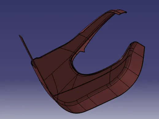
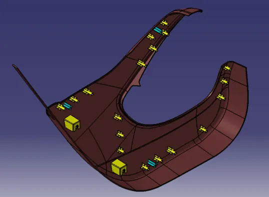
(Solid Model) (Engineering features)
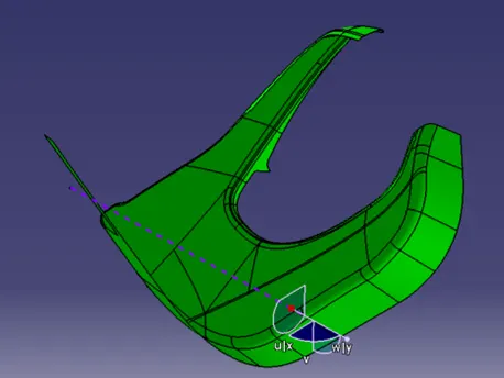
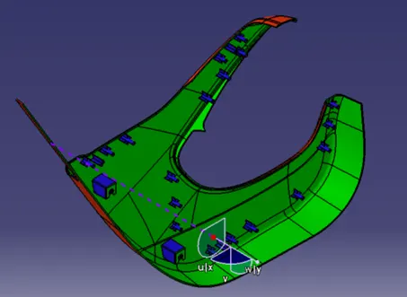
(Class-A Surface Draft Analysis) (Final Part Draft Analysis)
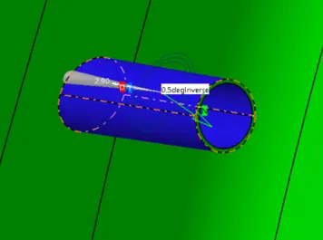
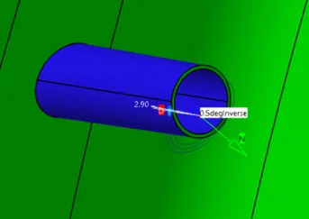
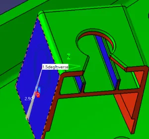
(Heat Stake Outside wall analysis) (Heat Stake Inside wall analysis) (Doghouse Outside wall Analysis)
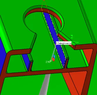
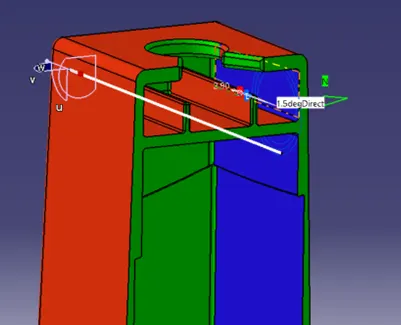
(Rib Anaysis) (Doghouse Draft analysis through lifter axis)
Sketches of Engineering Features:
1. Four-Way Locator Sketch
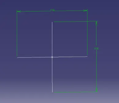
2. Doghouse Outer walll and ribs Sketch
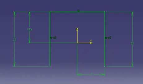
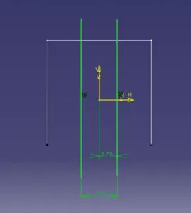
3. Heat Stake sketch
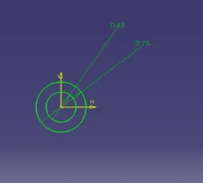
Push Clip Design
ASSEMBLY DESIGN
The assembly is mainly done by constraining the degrees of freedom of the parts and coinciding the mating parts wherever needed. In this assembly the door lower substrate is fixed and all other parts are assembled using point to point and axis to axis coincident constraints.
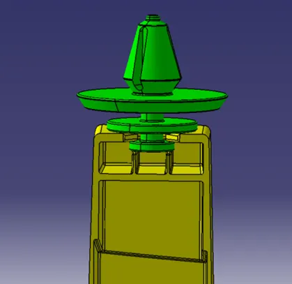
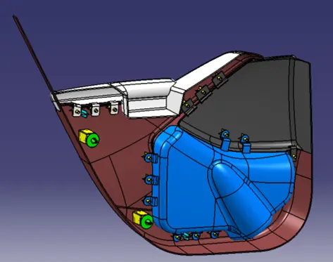
(Assembly of Pushclip and doghouse) (Assembly of all parts)
Final Product
Conclusion
From the given Class-A surfaces and master sections, the Class-B and Class-C surfaces are created to prepare a solid model. The engineering features created on each solids are for the purpose of attaching to other parts and restraining degrees of freedom. All engineering features follow the necessary design rules. The final part is analysed for drafting and the results show that degrees of drafting for each part and engineering features are according to manufacturing parameters. Plastic material is applied and all parts are assembled hence, the final door trim panel is developed.