Door Arm Rest Design
Aim - Create the Door Armrest component using the given Class-A Surface of the armrest and the the door.
Objectives:
- Create CLASS B and Class C Surface for the Door Armrest using the given Class A Surface.
- Use the given Class A Surface of the Door for reference.
- Use the Close Surface feature to make a solid body from the surface.
- Use the publication option and publish the Class A, Class B, Class C Surfaces and the tooling axes.
Tooling Axis:
The first step in creating the other surfaces is the construction of the Tooling Axis.
- Extract the boundary of the hole in the Class A surface and fill it. Create a point on the surface at the centre using the Point command.
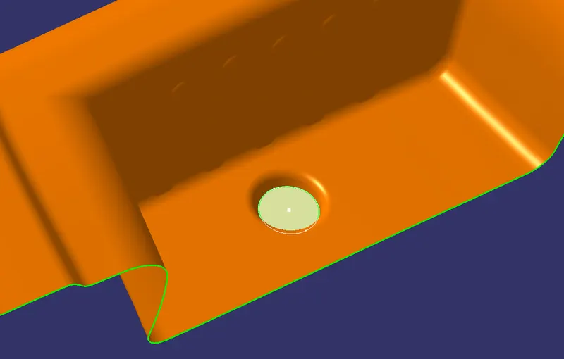
- Put the Class A surface in the material mode and open the Feature Draft Analysis Tool.
- Select the surface and drag the compass onto the surface.
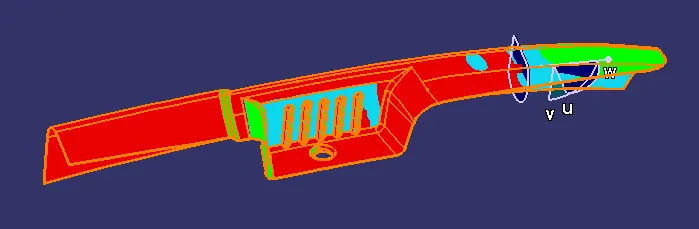
- Now the orientation of the compass can be changed and the draft analysis can be visualized simulataneously.
- Lock the compass at the position where the draft analysis gives the best results.
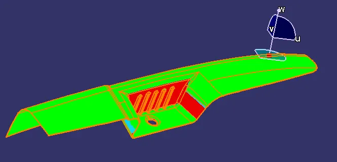
- Use the previously created point and the compass direction to construct a line which is the main tooling axis.
- Follow the same steps for the pocket region and lock the compass orientation
- Extract the rib surface and untrim it:
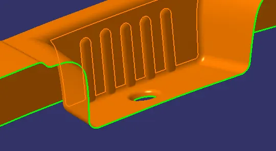
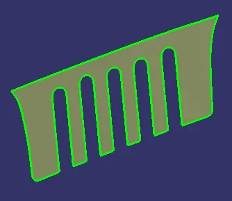
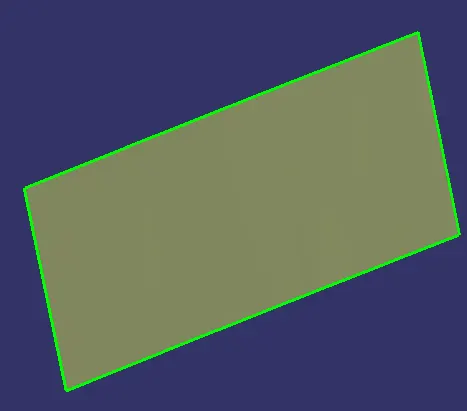
- Create a point at the centre of the untrimmed surface. Create a line using the point and the direction of the compass.
- This will be the second tooling axis.
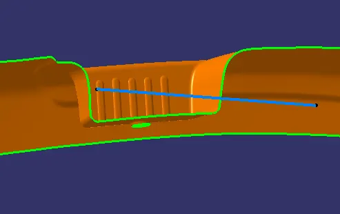
- Finally, use the Publish feature to publish both the tooling axis and the Class A Surfaces.
Class B Surface:
Pocket:
- Extract the pocket surfaces from the Class A surface:
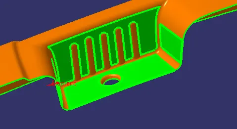
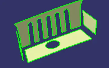
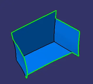
- Untrim the extracted surfaces and then extrapolate the untrimmed surfaces such that they intersect each other:
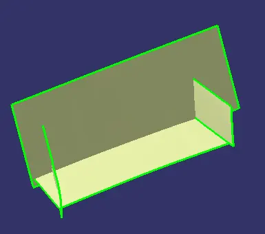
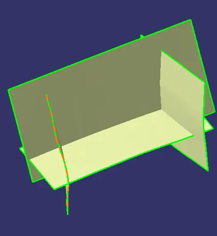
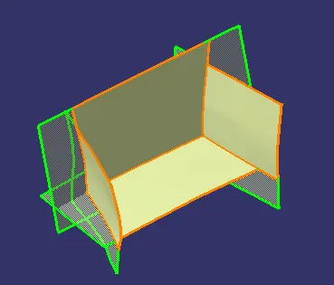
- Offset the extrapolated surfaces to a distance of 2.5mm and trim them together:
Middle Surface:
- Extract the middle surfaces from the Class A surface:
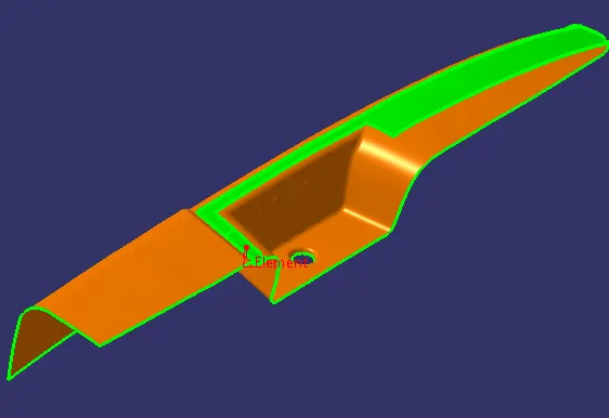
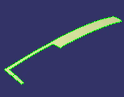
- Untrim the extracted surfaces and then extrapolate them:
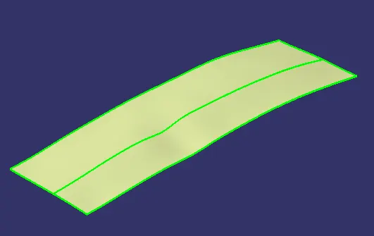
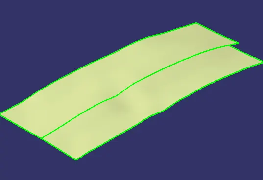
- Join the extrapolates surfaces together and create an offset of 2.5mm:
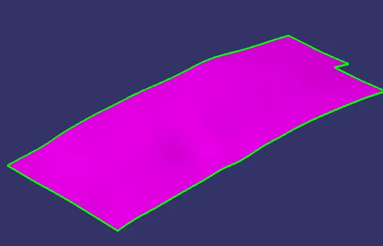
Fillet Surface:
- The fillets at the backside of the Class A surface can not be created directly because is both the surfaces are trimmed together, there will only be a single surface but there are two fillets:
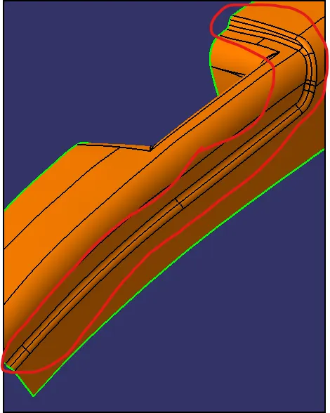
- Extract the fillet edges from the Class A surface:
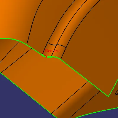
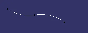
- Create midpoints on both the extracted curves and join them to construct a line:
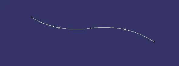
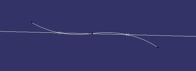
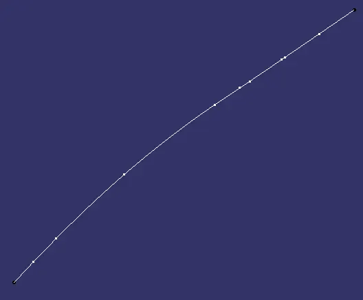
- Use the multi extract feature to extract the shared edges of both the fillets which will act as a guide curve:
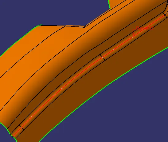
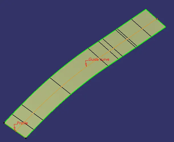
- Use the Sweep feature with subtype as 'With Reference Surface'. Choose the previously created line as the profile and the extracted curve as the guide curve:
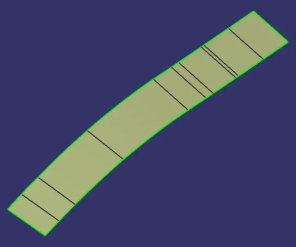
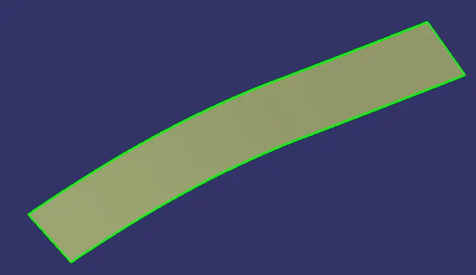
- Use the Surface Simplification feature on the swept surface. Extrapolated the smooth surface and offset it to 2.5mm:
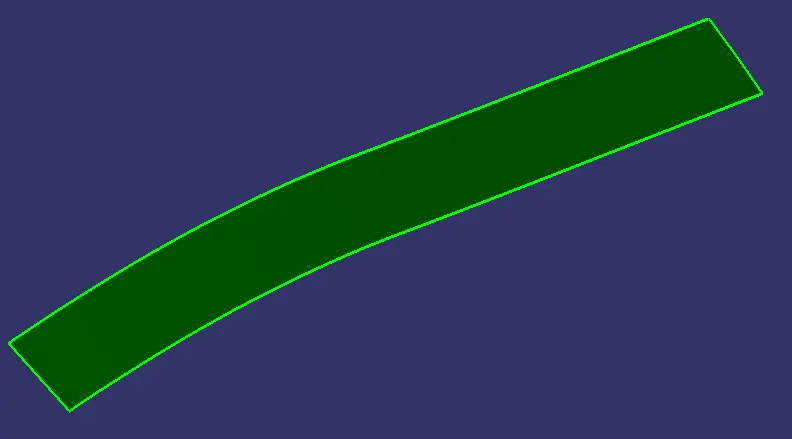
Inclined Strip:
- Extract the inclined strip surface from the Class A surface:
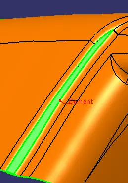

- Untrim the surface and then extrapolate the untrimmed surface.
- create an offset of the extrapolated surface of 2.5mm:
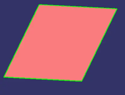
Back Surface:
- There are two surfaces on the back wall. Extract both the surfaces and untrim them:
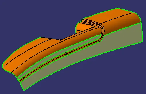
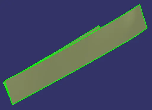
- Extrapolate and offset both the surfaces to 2.5mm:
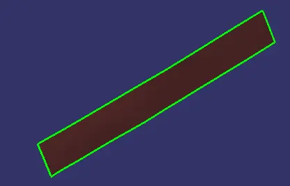
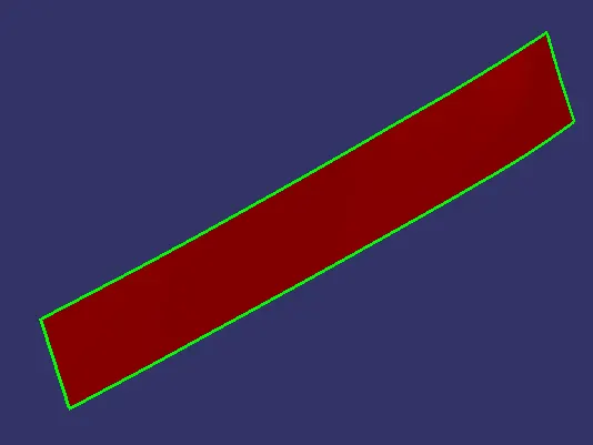
Top Surface:
- Extract the top surface and untrim it:
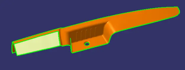
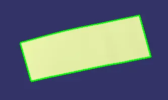
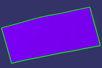
- Extrapolate the untrimmed surface and create its offset of 2.5mm:
Hole:
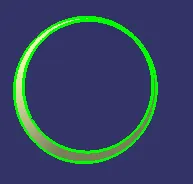
- At the bottom of the Class A Surface, there is a hole with inclined cylindrical walls. Firstly extract the boundary of the hole and then the cylindrical surface:

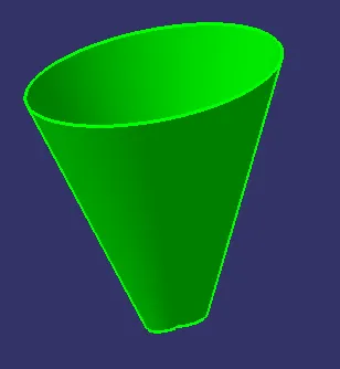
- Extrapolate the surface in both directions and create its offset of 2.5mm:
Final Trims:
- Before trimming all the surfaces together, the inclined surface needs to be modified.
- On the inclined surface, create curves using the 'Parallel Curve' feature such that the curves do not touch the pocket surface.
- Trim these curves and split the inclined surface using these curves:
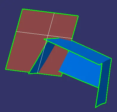
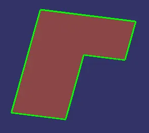
- Trim the pocket surface and the middle surface together:
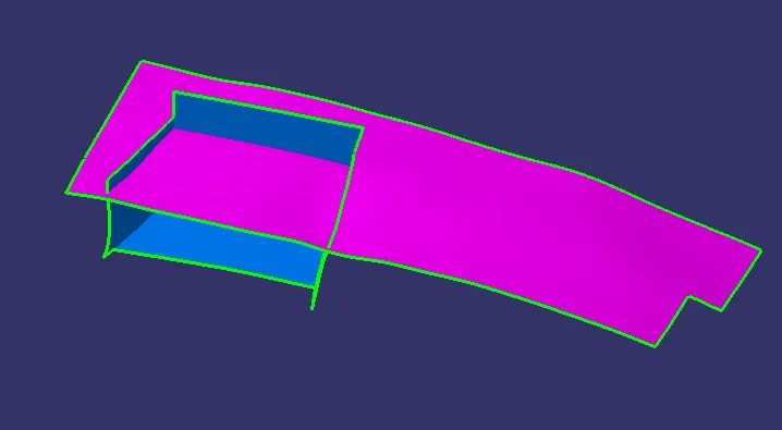
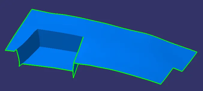
- Trim the upper back surface and the last trimmed surface together:
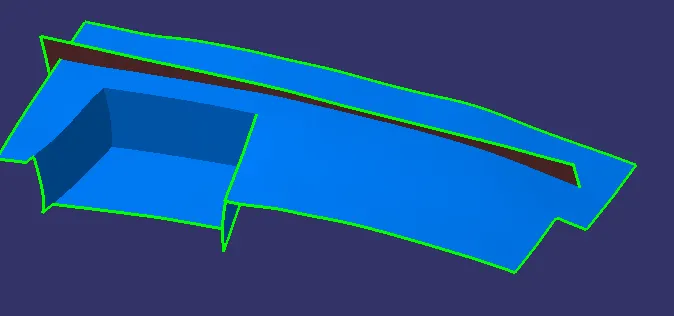
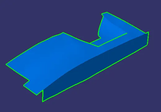
- Trim the fillet surface and the last trimmed surface together:
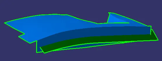
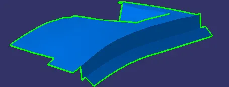
- Trim the modifies inclined split surface and the last trimmed surface together:
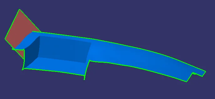
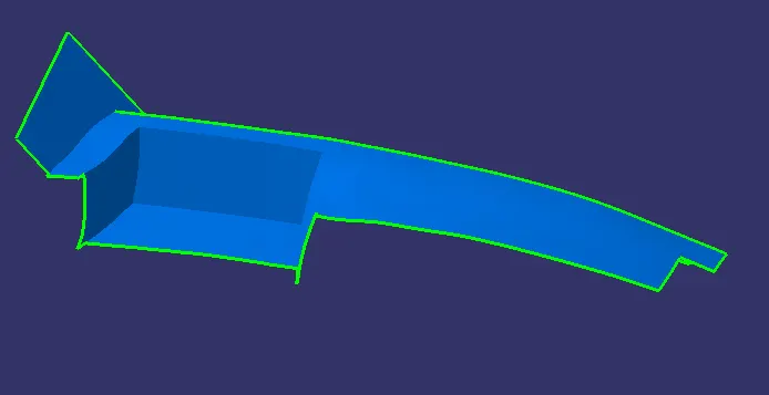
- Trim the top surface and the last trimmed surface together:
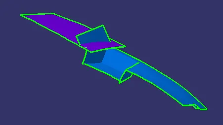
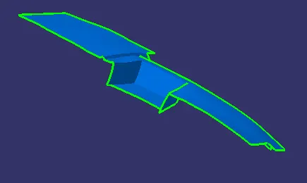
- Now trim the lower back surface and the last trimmed surface together:
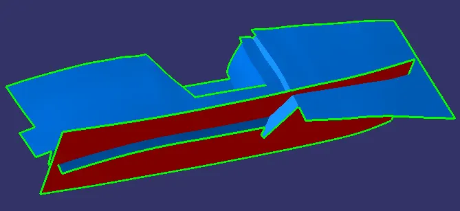
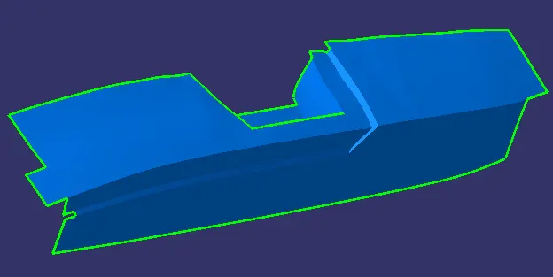
- Finally, trim the frustum surface with the last trim:
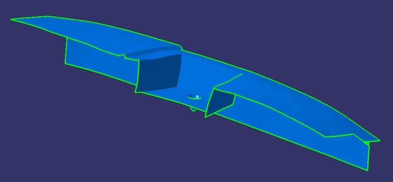
Fillets:
- Provide fillets on edges taking reference from the Class A surface.
- The fillet radius needs to be chosen keeping in mind the thickness of the component such that when the final part is created, it has a uniform thickness of 2.5mm:
Class B Surface 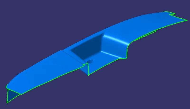
Class C Surfce:
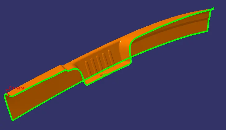
- Extract the enclosing walls of the outer flange using the Multiple extract feature:
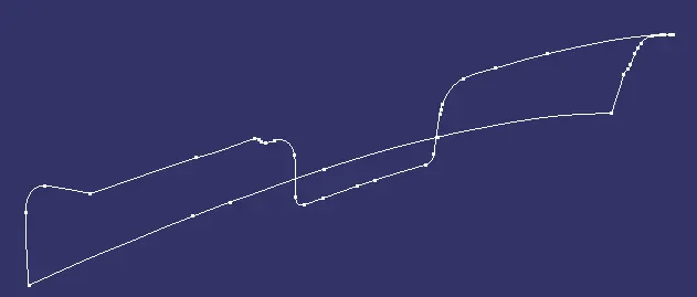
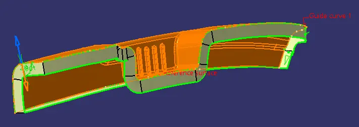
- Use the Swep feature using the extracted boundary as the guide curve and the Class A surface as the reference surface
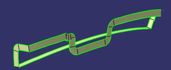
- Now extract the hole boundary and similarly speep it using the Class A surface as the reference surface.
Closed Surface:
- Join the Class A surface and the Class C surfaces using the Join feature:
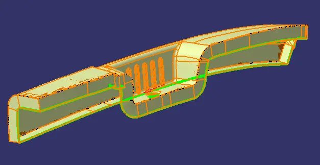
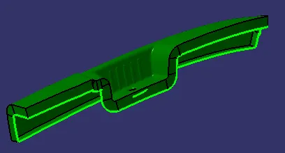
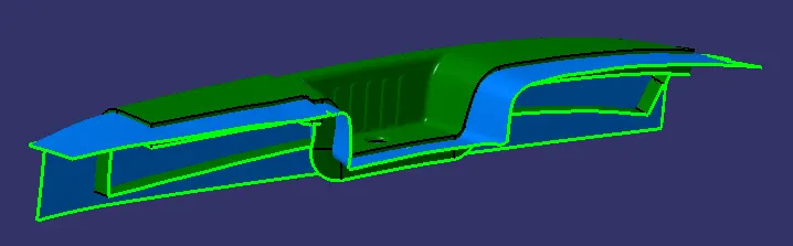
- Finally, trim the the above surfaces and the Class B Surface:
Closed Surface 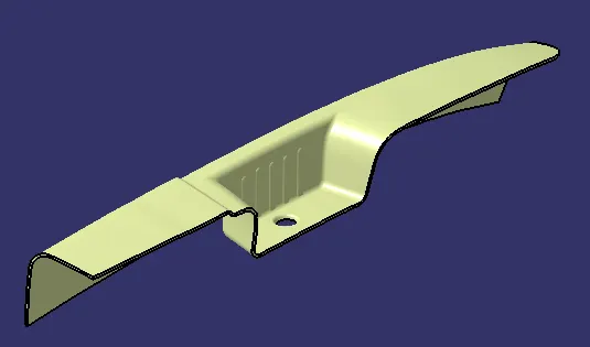
Solid-Body:
- Use the Close Surface feature and select the above surface to create a solid part.
Part Body 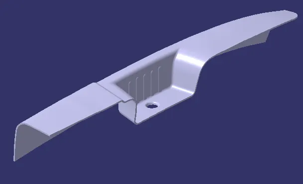
Draft Analysis:
- For the draft analysis, open the Feature Draft Analysis tool and drag the compass to the main tooling axis and select the body:
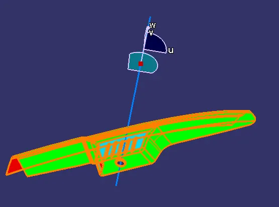
Draft Analysis (main tooling axis) 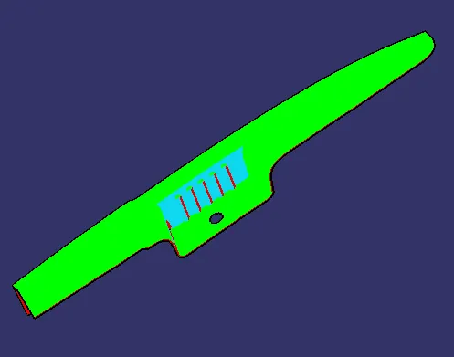
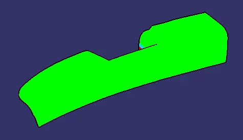
- For the draft analysis of the pocket region, gain open the feature draft Analysis tool and drag the compass to the second tooling axis and select the body:
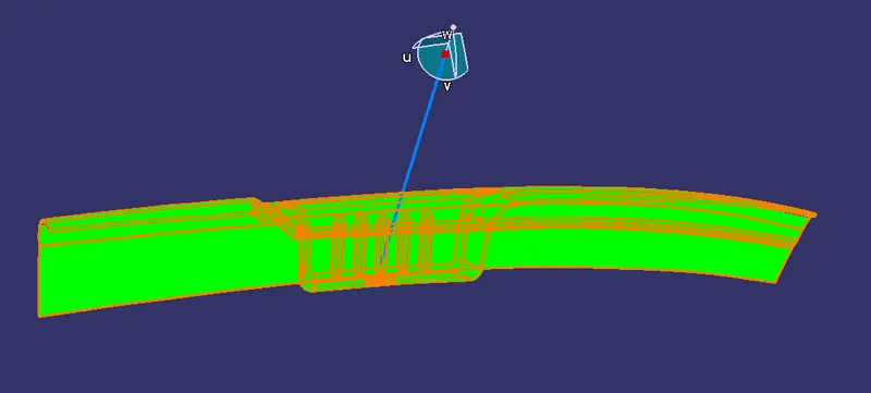
Draft Analysis (side core tooling axis) 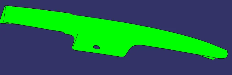
Conclusion:
- The main tooling axis and the side core tooling axis have been created successfully using the Feature Draft Analysis Tool.
- Class B and Class C surfaces have been successfully created using the Class A surface as the reference.
- Final Closed Surface has been created by using the Trim and Join feature.
- The part body has been created using the final closed surface.
- Draft analysis has been successfully done on the part body.