Door Arm Rest Week 8 Challenge
Aim/Objective:
Creation of Door Arm rest and add thickness to it.
Detailed Report:
Terms used:
- Class A surface: It is outermost surface of automobile which gives aesthetic look to vehicle. It is physically touchable. It is obtained from clay modeling by reverse engineering. This surface is given input to plastic product designer to work.
- Class B surface: This surface is created by taking offset from class A surface. It is surface on which all engineering feature like screw bosses, dog house, ribs & mounting are created.
- Class ‘C’ surface: This is surface which joins class A & class B together.
- Tooling axis: It is the direction in which core & cavity opens & closes.
- Slider Direction:
Due to the special requirements of a product, the mold release direction of a particular part may not be consistent with the mold opening direction of the injection molding machine (product undercut), the slider, also known as slide, is a mold mechanism that is developed to solve the issues with the undercut. The basic principle is to turn the vertical movement of mold opening / closing into a horizontal motion. In order to cope with the situation that the undercut is located in the core or cavity, different structural forms are developed.
Method followed:
- Checking continuity of class A surface.
- Deciding feasible tooling direction & creating tooling axis.
- Performing draft analysis on class A surface.
- Creating class B surface from given class A surface.
- Creating class C surface to join A & B class surface.
- Creating solid feature by using closed surface.
- Performing draft analysis on final plastic component
1. Checking continuity of class A surface.
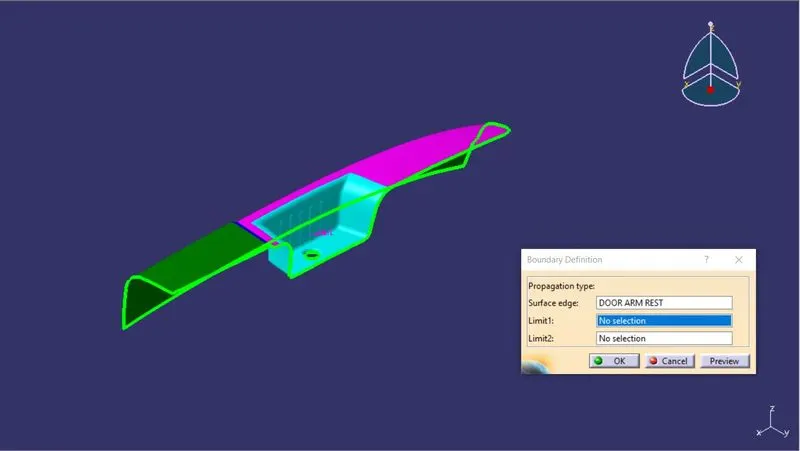
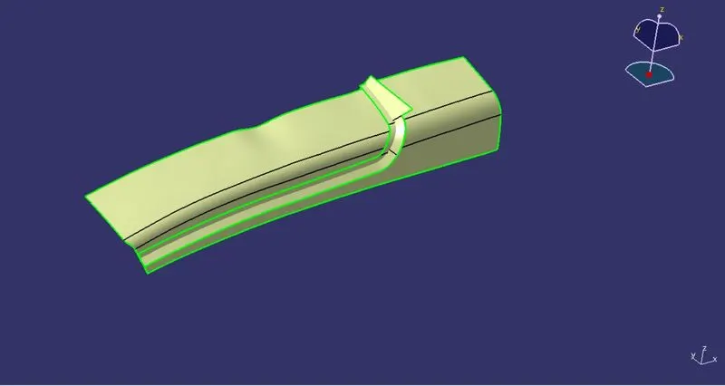
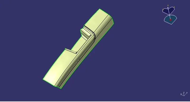
We have to check continuity of given class A surface to ensure class A surface is properly joined or no discontinuity present. This can be done by using join or boundary command in CATIA. By looking visually in below image we see that surface has continuous connected boundary as highlighted by green line. Also this boundary separated into two domains.
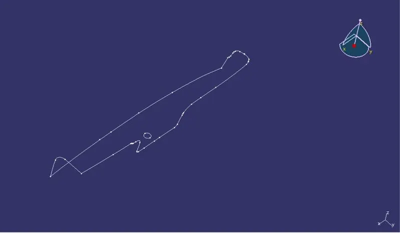
- Extracting the boundary of given class A surface we also check that continuity visually. Below figure shows door arm rest model has continuity in class A surface.
2. Creating tooling axis direction:
Tooling axis is the direction in which core & cavity or mould opens & closes. A small draft angle is provided to each & every area of the component in order to get an easy removal of the component from the tool. Draft analysis technique is used to analyze whether our part model created in cad is manufacturable based on the draft condition applied. So for draft analysis tooling axis is primary requirement. Here we are providing a direction in which components should eject in order to get an easy removal of components from the tool. In simple model one tooling axis is sufficient to clear the model. But for complex component, we have to provide side core. So needs more tooling direction to clear entire component. So first we have to create main tooling axis for all surface except for side core surface or pocket.
- Creating main tooling axis & slider direction:
- First extract the base surface & create point on that surface. Insert axis system at that point. Take intersection of class A surface with the XZ plane of axis system. Create two lines along the vertical faces. Create line using bisecting method & passing through that point.
- Perform draft analysis using that line as tooling axis. We observe that few faces of component are not in green. So tilt compass like wise to achieve entire top surface & back surface are in green color except pocket surface. Lock the position of compass.
- Create the line in by choosing direction as compass direction & passing through point on base surface. This is our main tooling axis. After that unlock compass & reset it.
- Likewise follow same process & create slider direction. Extract the vertical rib face & create point on it. Draw a line through point & normal to that surface. Perform draft analysis by aligning compass to that line. Make all pocket surface color green with help of compass. Lock the compass direction. Modify line direction. This is slider direction.
- Performing draft analysis on class A surface:
1. To perform draft analysis. Go to insert < Analysis< Feature draft analysis.
2. Switch customize view parameter mode to
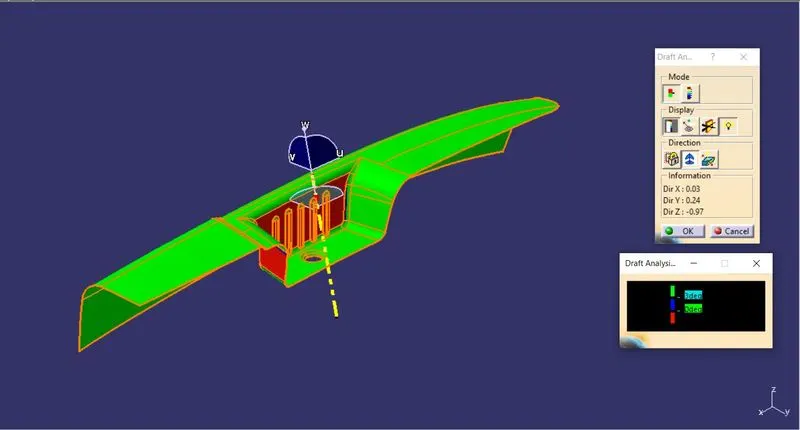
3. Click on compass icon & align it with the tooling axis & click on the surface, we will get our results.
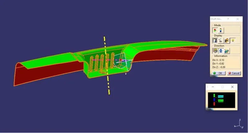
4. From the below image it is seen that surface in green color has more than 3° draft which is most required for tooling feasibility. Also see color variant display box.
- Draft analysis using main tooling axis:
- Draft analysis using slider direction:
- Creating class B surface from given class A surface.
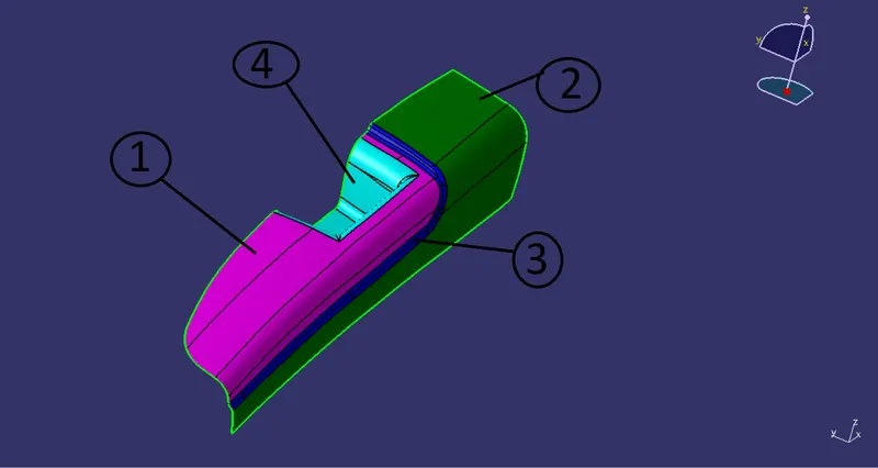
Divide class A surface into surfaces namely first half, second half, connecting fillet surface & pocket surface as shown below image. Work on each surface separately to obtain class B surface.
- First half: surface marked in pink color.
- Second half: surface marked green color.
- Connecting fillet surface: surface marked in blue color.
- Pocket surface: surface marked in cyan color.
Follow the same procedure for all surfaces except for connecting fillet surface.
- Extract the class A surface.
- Un-trim the surface.
- Extrapolate untrimmed surface.
- Offset it by 2.5 mm distance.
- Trim unwanted extra surface.
- Applying fillet as per formula to obtain uniform wall thickness.
*If surface need to offset outside then fillet = class A surface fillet + thickness of part.
*If surface need to offset inside then fillet = class A surface fillet - thickness of part.
First half:
- Extracting the class A surface.
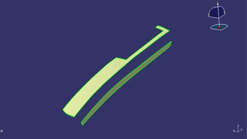
- Un-trim the extracted surface.

- Extrapolate the untrimmed surface.
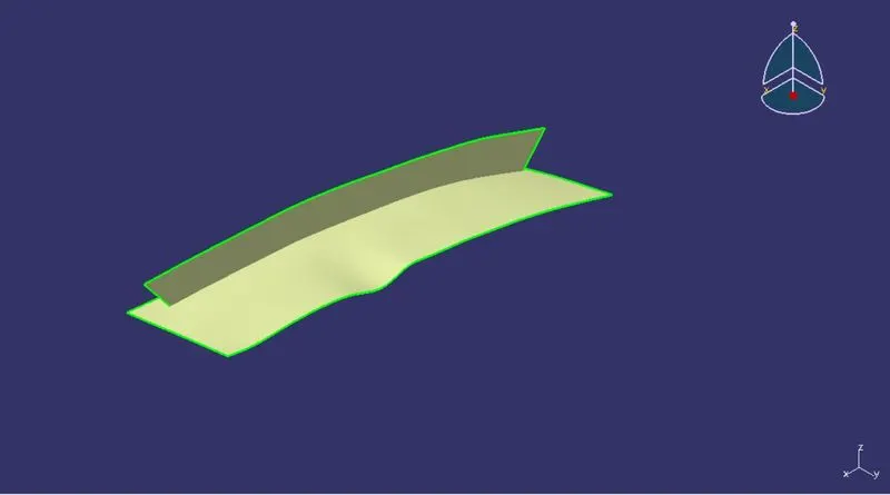
- Offset it by 2.5 mm distance.
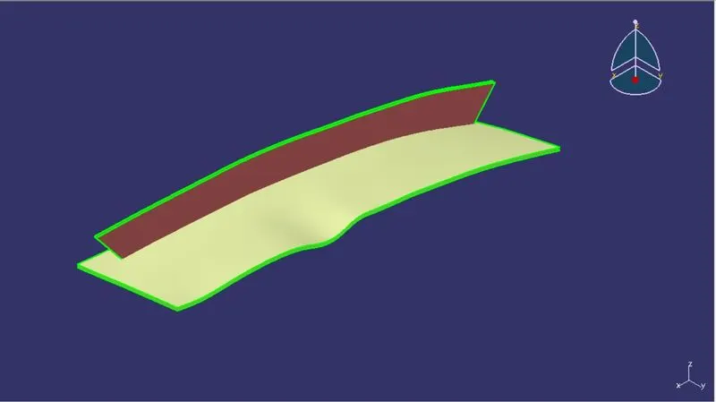
- Trim unwanted extra surface.
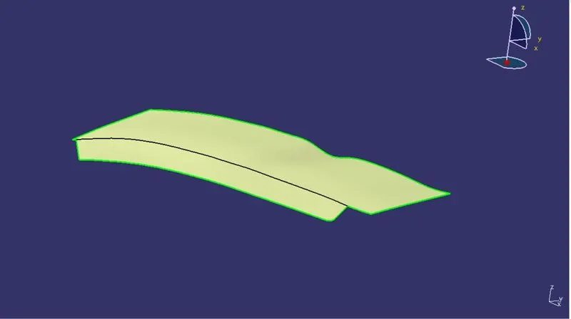
- Applying fillet as per formula to obtain uniform wall thickness. (R= 17 -2.5= 14.5 mm.)
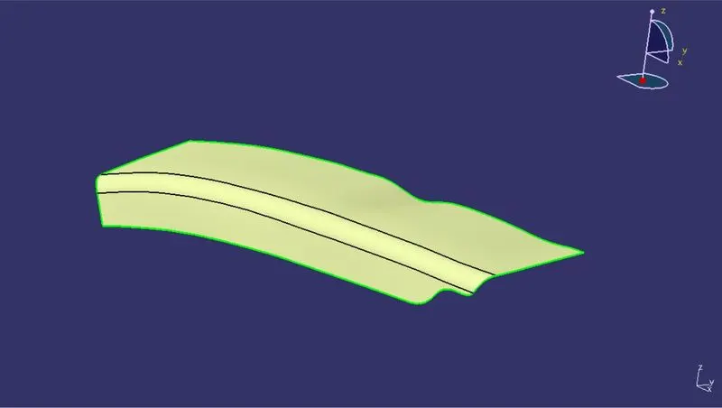
- Following same procedure for second half & pocket we get following surfaces.
Second half:
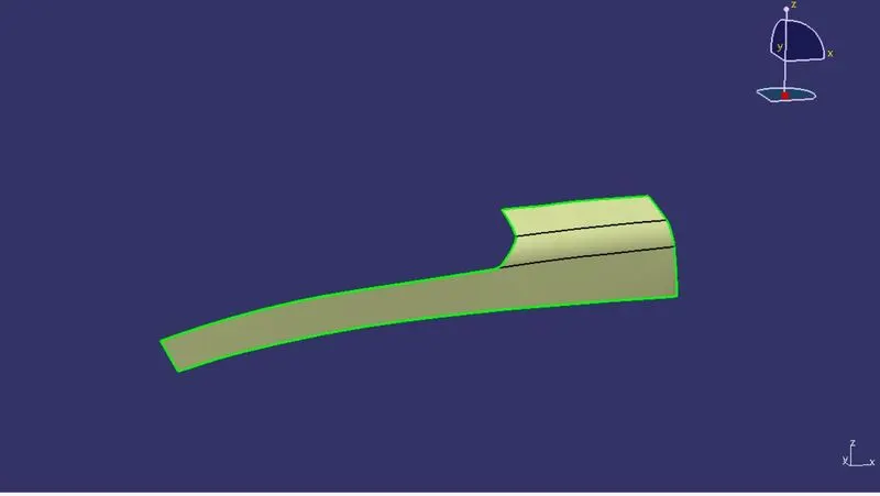
Pocket surface:
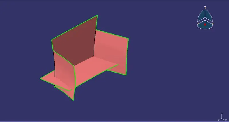
- Creating connecting fillet surface between first & second half:
First draw a point as shown in figure. Take axis system at this point. Invoke sketcher workbench by selecting YZ plane. Take intersection of class A surface in the sketch. We get fillet profile. Draw a tangent line to fillet. Constrain the line. Exit sketcher workbench.
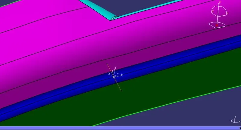
- Extract the fillet edge as shown in figure.
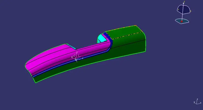
- Make sweep surface using line as profile & extracted edge as guide curve.
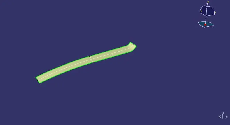
- Offset this surface by 2.5 mm
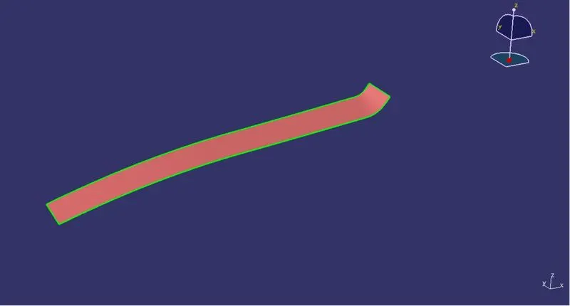
- Extract the small flat surface as shown in figure.
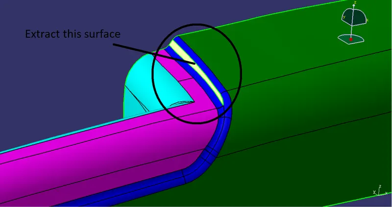
- Un-trim & offset it
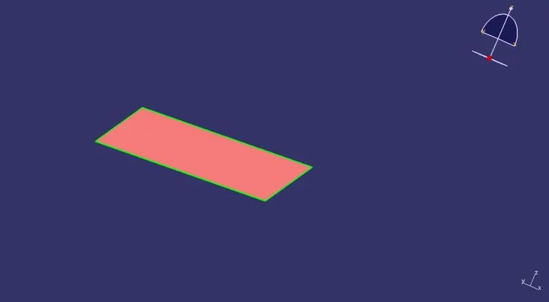
- Now split this surface with line at appropriate angle to get proper blend surface.
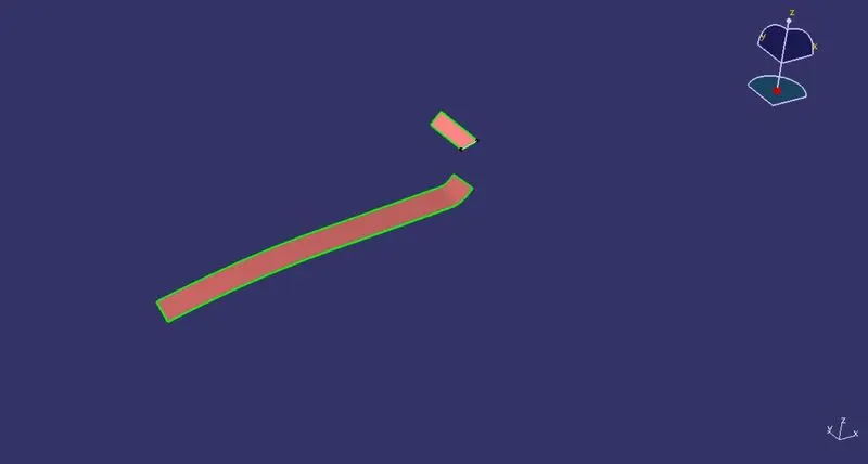
- Create blend surface & join this three surfaces together.

- Extrapolate this blend to proper intersection with first & second half.
- Trimming these surfaces together (i.e. first half, second half & connecting fillet & pocket surfaces together we get final B class surface. Fillets all remaining edges as per formula.
5. Creating class C surface to join A & B class surface.
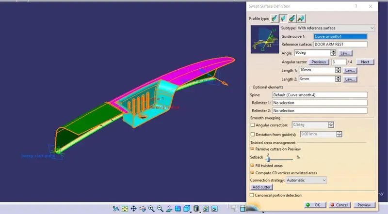
- To obtain C class surface followed below method. Entire C class is created in steps.
- First sweep extracted curve at 90° to reference surface as shown in below image. This is first part C class surface created.
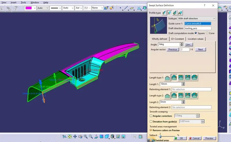
- Sweep curve in draft direction & created surface as shown in below image. Three patches of surfaces created.
- Now extrapolated swept surfaces then split by line & formed multi-section surfaces.
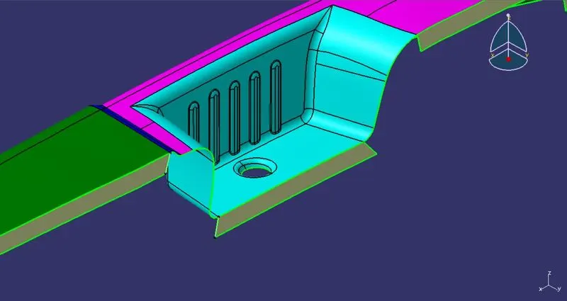
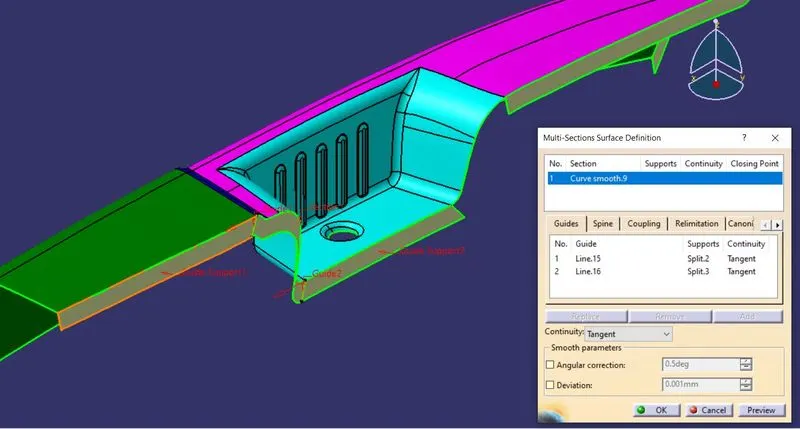
- Followed same method & all remaining C class surface created
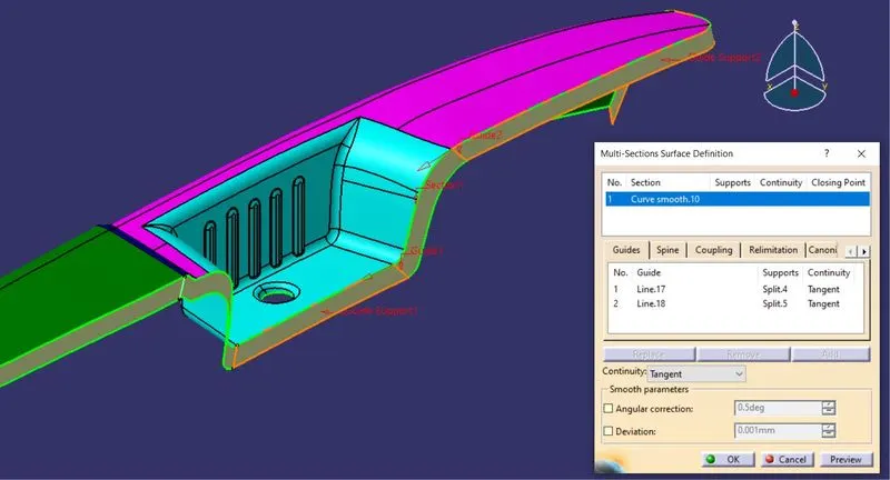
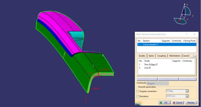
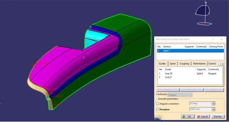
- Final C class surface is as shown in below figure.
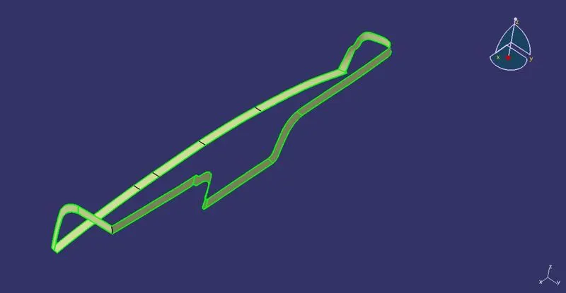
- Join Class A & C surface together.
- Trim this joined surface with B class surface result in closed surface.
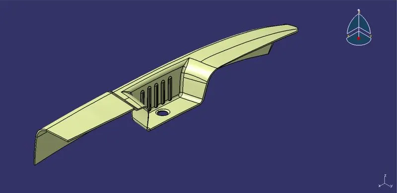
6. Creating solid feature by using closed surface.
- Solid model is created from closed surface in the part workbench by using close surface command.
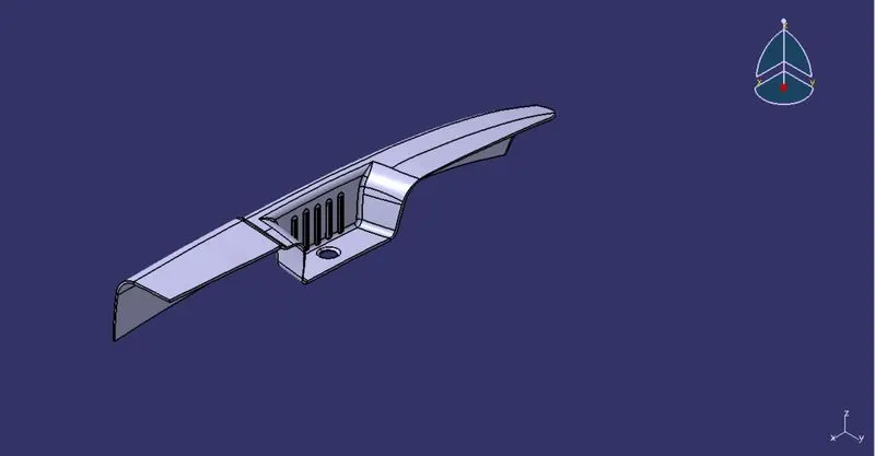
7. Performing draft analysis on final plastic component.
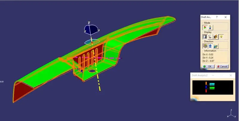
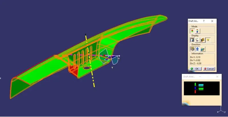
- Performing the draft analysis again with the same procedure as mentioned above for the class A surface.
- Draft analysis using tooling axis.
- Draft analysis using slider direction.
- Images of the solid model with the proper color code of the draft angle in various orientations (Isometric, Front, Side, and Top View).
ISO view:
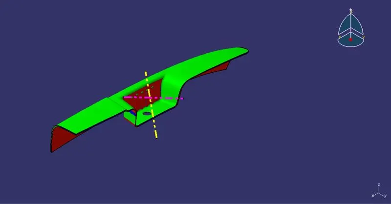
Front view:
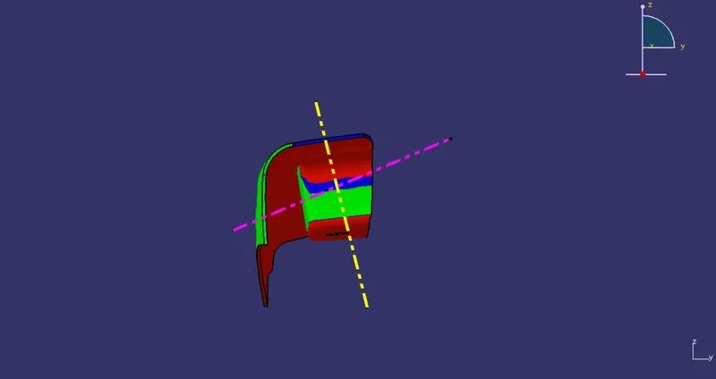
Left side view:
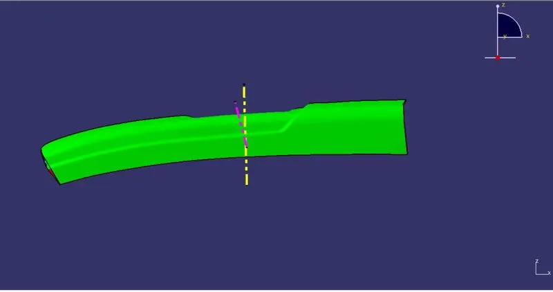
Right side view:
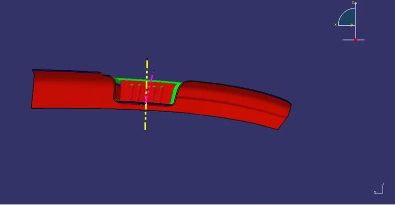
Top view:
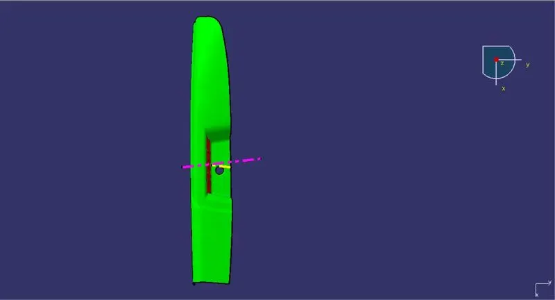
- Image of the expanded tree structure for the geometrical sets & part body.
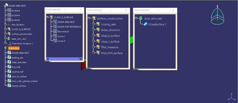
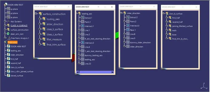
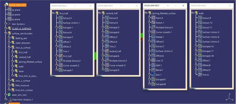
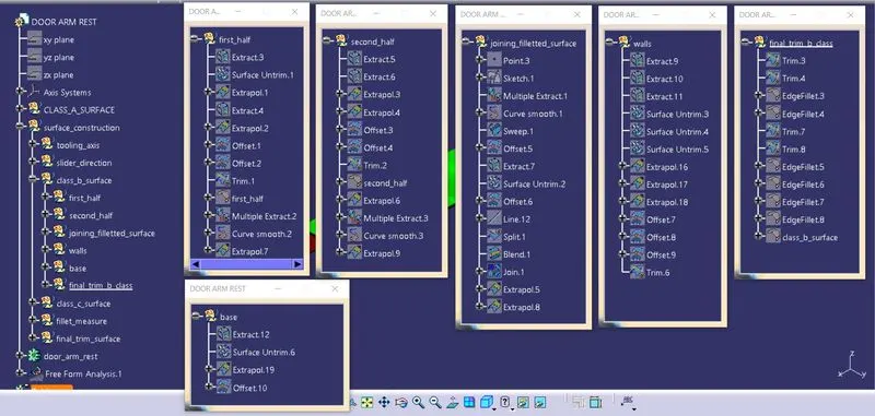
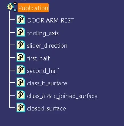
- Image of the publications of tooling axis & class A, B & C surface.