Door Arm Rest Week 8 Challenge
Automotive Plastic Design using CATIA V5
AIM: To Create the Door Armrest and add thickness to it
Requirements:
- Create tooling axis following the OEM standard
- Follow the instructions given in the video a solid.
- Part Thickness : 2.5 mm
- Send output in a ppt following the instruction given in the instruction page
- Output ppt must contain the draft analysis report
PROCEDURE:
- Open CATIA V5 and import the given class-A surface.
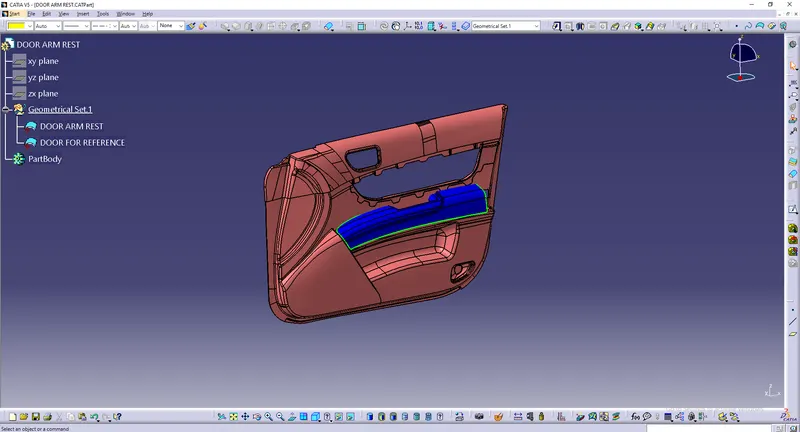
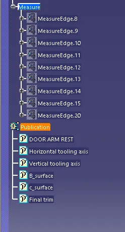
- Use the publication tool to publish class A surface , which helps the user to find the class A surface faster.
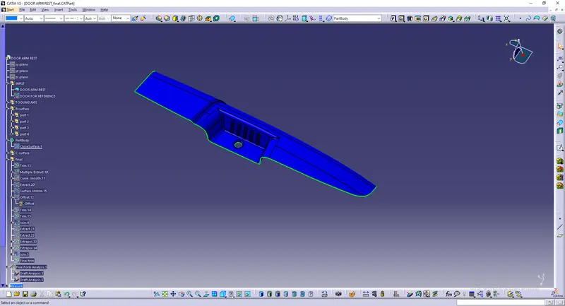
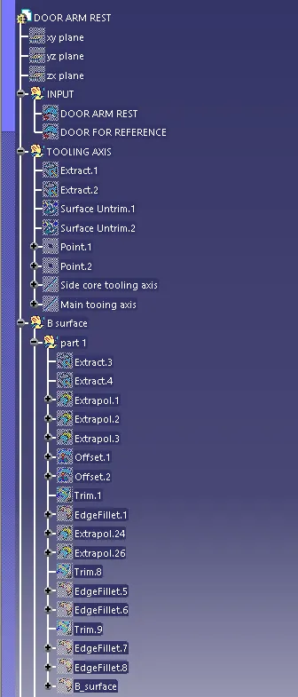
- Now, we have to create the tooling axis for the class A surface. For this model we have to create two tooling axis one is the main tooling axis and other is the side core tooling axis as the model have some compicated parts to manufacture.
- For creating the Tooling axis we have extracted the surface by using extract tool then un trimmed the ectracted surfaces and created a point using surface and the created a line normal to the surface.
- We repeated the same process for both the surface and obtained two tooling axis.
- Use the publication tool to publish the tooling axis , which helps the user to find the tooling axis faster.
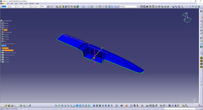
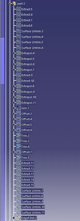
- Now we have to create the Class B surface.By using then class A surface we have to create the b surface by using commands like extract,un trim, and extrapolate
- In this Class A surface, we have some compiecated areas in the we face dificulty in achieving the class B surface.
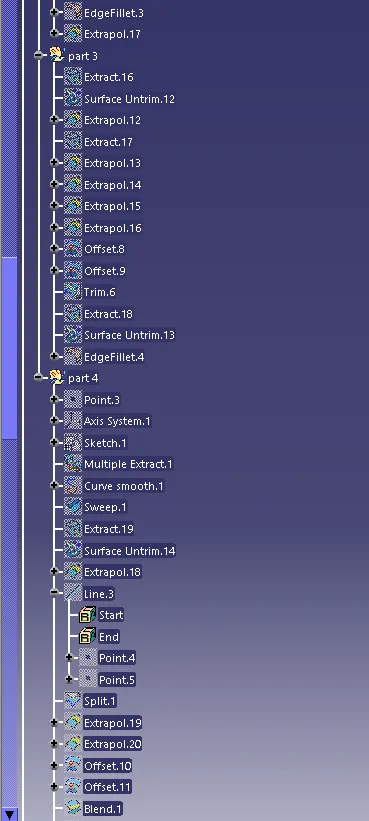
- In those areas we create a sketch and create a curve using multi extract option and then by using these to we create a surface with sweep option.
- We use Blend option to combind the two surfaces.
- Finally, apply the fillets to the B surface by measuring the fillets on the class A surface. and the class B surface is obtained.
- Use the publication tool to publish class B surface , which helps the user to find the class B surface faster.
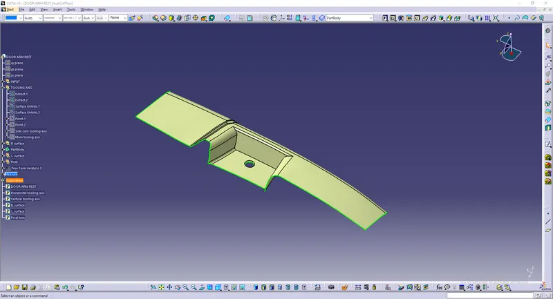
- Now we have to create the Class C surface
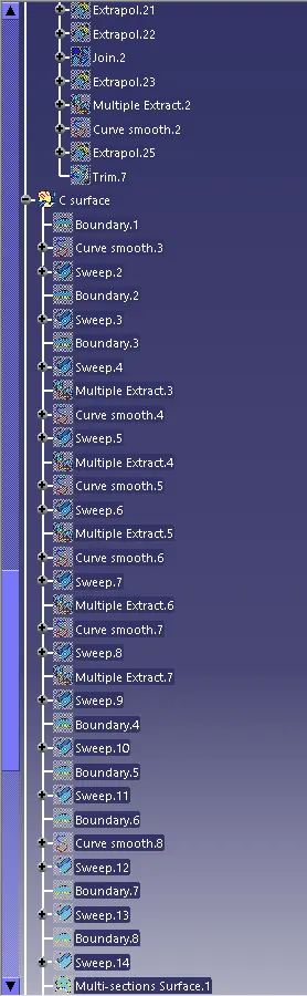
- Use Multi extract and boundry command and select the edges from class A surface.
- Use sweep command and select Draft angle and direction. By using tooling axis we create The Class C surface.
- Use the publication tool to publish class C surface , which helps the user to find the class C surface faster.
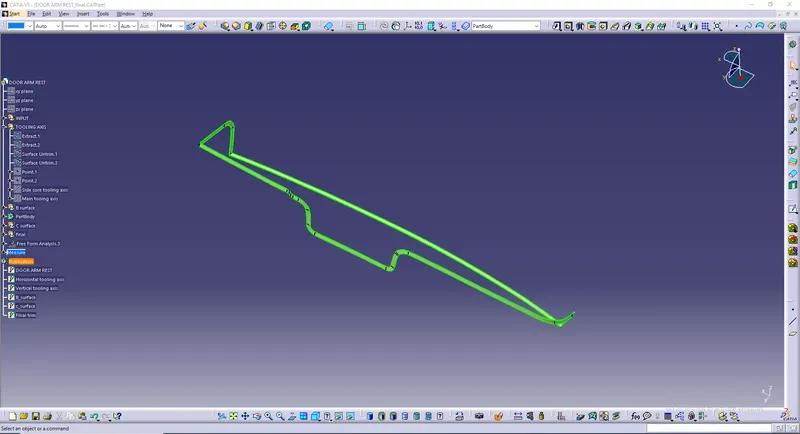
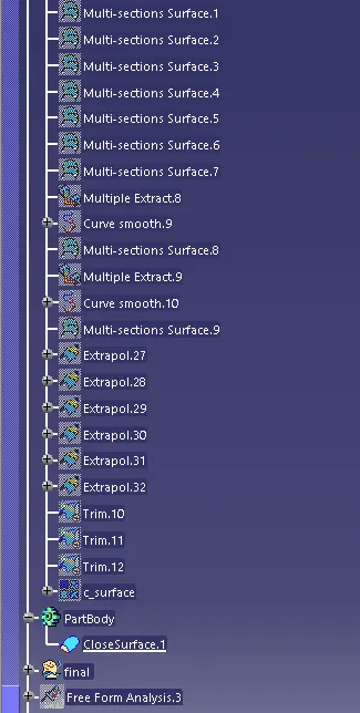
- Now use the join and trim commands and attach the class A, Class B and Class C surface.
- Finally we will have the surface model. ensure that all the boundries are closed.
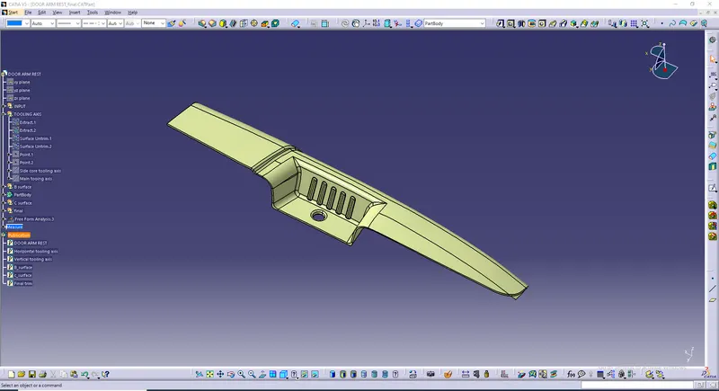
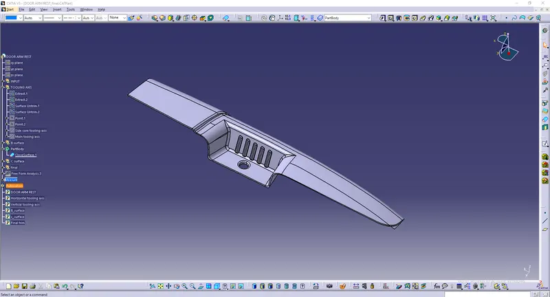
- Now, using the surface model we have to create the solid model by using close surface option in the part design.
- Finally, we will have the solid model.
- Now we have to do the draft analysis on the model but before that set the viewing mood to material mood.
- Now, go to draft analysis,click in the compass option in direction and bring it to the tooling axis and lock the compass.
- Give the draft angle mim and max).
- Finally the draft analysis is performed on the model.
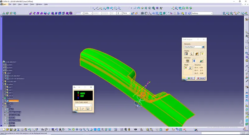
"Draft Analysis by using main toolig Axis"
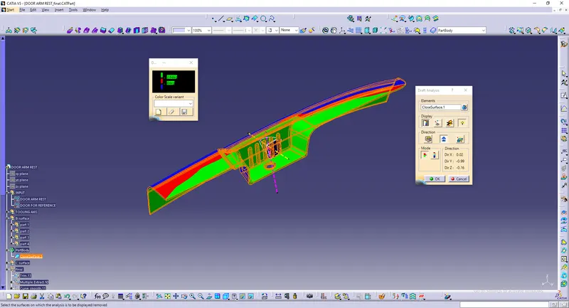
"Draft Analysis by using side core toolig Axis"
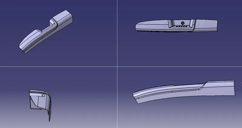
WHOLE MODEL:
TREE:
VIEWS:
CONCLUSION: Finally we have Created the Door Armrest and add thickness to it according to the requirements.