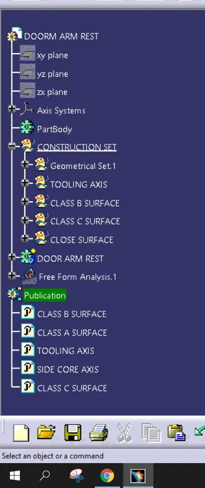
Door Arm Rest Week 8 Challenge
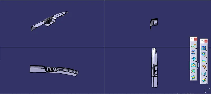
AIM: To create a Solid 3D DOOR ARM REST from a given CLASS A SURFACE.
OBJECTIVE:The objective is to create a Solid DOOR ARM REST from a given CLASS A SURFACE. following design rules.
CLASS A SURFACE:
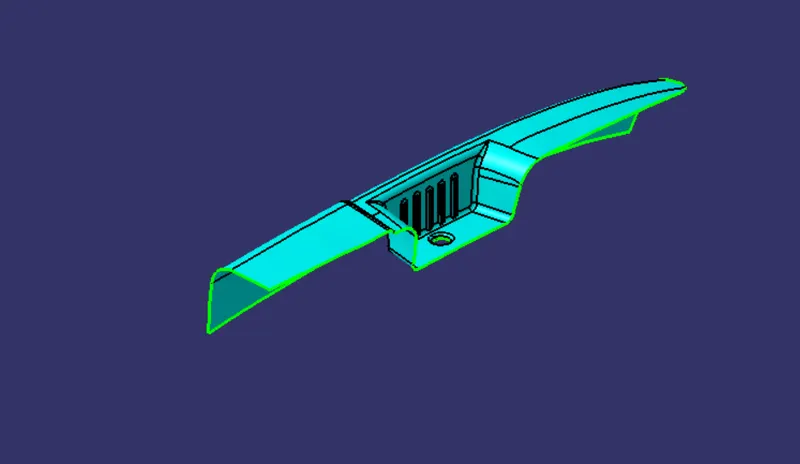
CLASS B SURFACE:
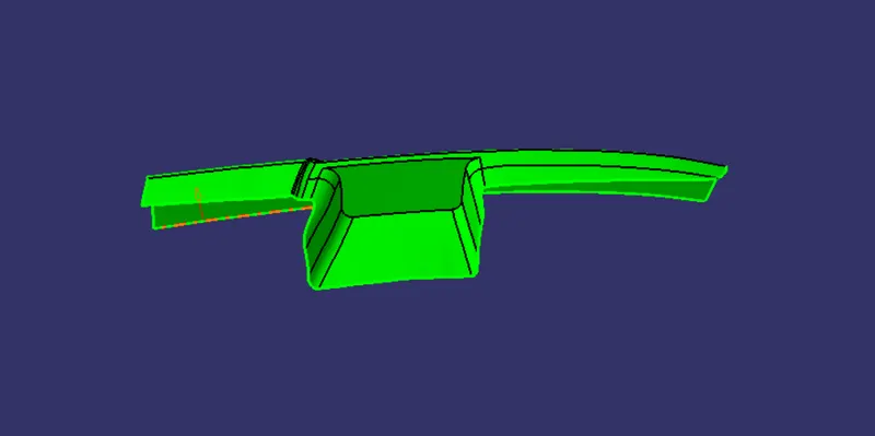
CLASS C SURFACE:
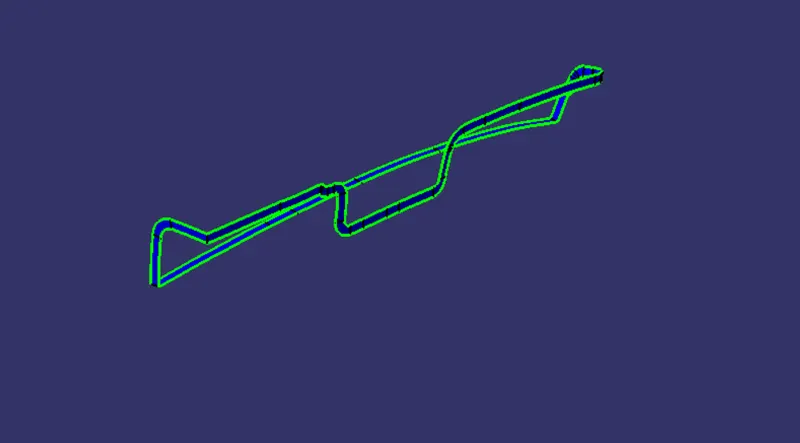
TOOLING AXIS:
SOLID DOOR ARM REST:
TOOLING AXIS CREATION:
- Master Section is first analysed for creation of tooling axis which tells about the direction of the mould or core and cavity slides.The tooling axis plays a vital role in the plastic design as there should be clearance between the tooling axis and mould.
- The minimum of 3 degree draft angle is provided on the surfaces which are 90 degrees to avoid the Interference between the mould and Injection moulding machine.
- The first step is to check whether the given class A surface has continuity or not.
- The next step is to check the possibilities of the tooling axis along x,y and z direction(NOTE : The surfaces must have clearance with the tooling axis and features such as holes must be cleared in the main tooling axis itself to avoid sidecore.)
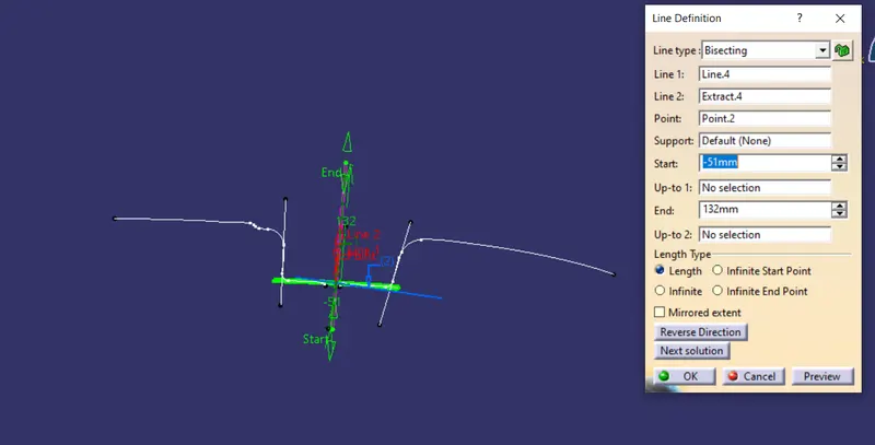
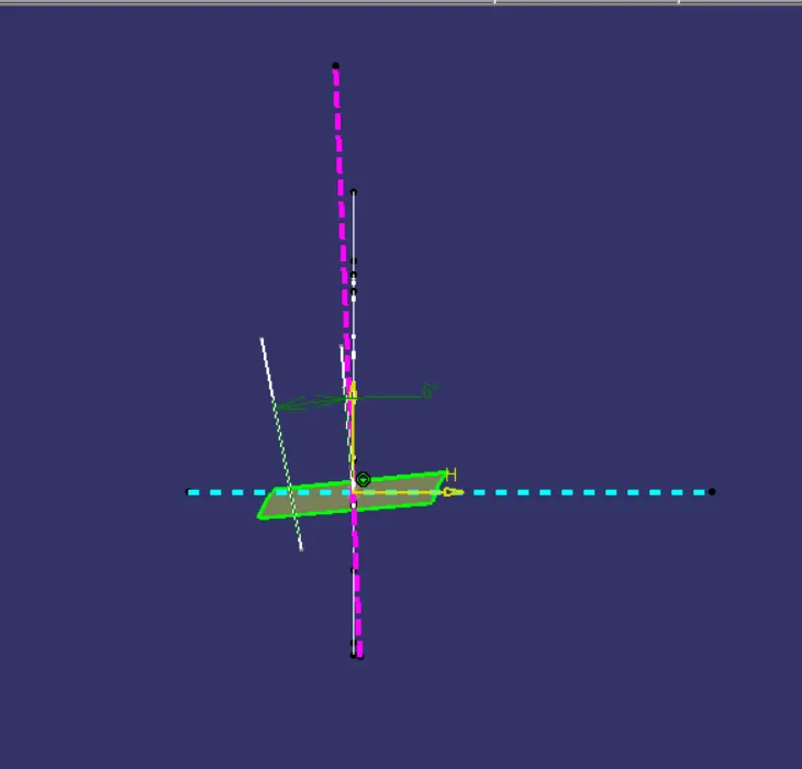
- The Tooling clearance along x and Y are created and by using the bisecting line and tooling axis along x,y we will draw a TOOLING AXIS in which features like Hole and the inclined surfaces don't interfere with tooling axis.
- The Tooling axis should be published along with changing the graphic properties of the Tooling axis for ease of recognition.
- Here there is no opposite face in the y direction so we have drawn a line and given a minimum of 3 degree draft,but later due to draft analysis we changed that to 6 degrees.
DRAFT ANALYSIS:
- Draft angle is nothing but the amount of the taper is provided on the core and cavity for ease ejection of the mould after cooling.
- After Injection moulding the plastic parts shrinks and gets stuck to the core and it will make it difficult to remove the plastic part.
- If no draft or taper is provided on the core and cavity the inner layers of the platic part will undergo wear and tear and there will be NO smooth surface finish.
- The draft angle is provided on both the inner and outer walls of the core and cavity.
- The Nominal draft angle is 3 degrees
- The 5 degree draft can be given by the manufacturing cost will be more.
- The 7 degree draft is given for the textured surface.
STEPS FOLLOWED FOR THE DRAFT ANALYSIS:
- The part created has to be changed to the material mode.
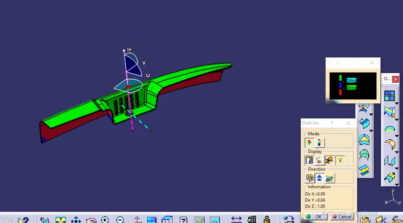
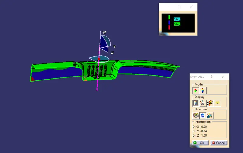
- compass is enabled and aligned to the tooling axis.
- Lock command is used to lock the position of the compass.
- colour codes are classified and draft angle is analysed.
- Running point analysis is used to display draft angle at a specific position.
DRAFT ANALYSIS ON CLASS A SURFACE:
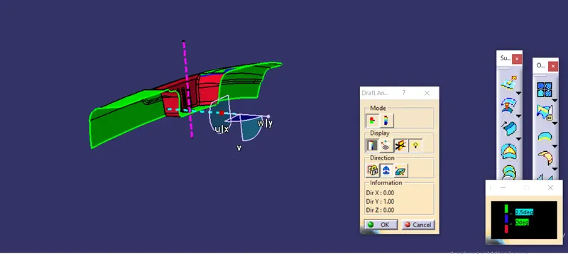
DRAFT ANALYSIS ON SOLID DOOR ARM REST: