Door Arm Rest Week 8 Challenge
Draft Analysis in Catia
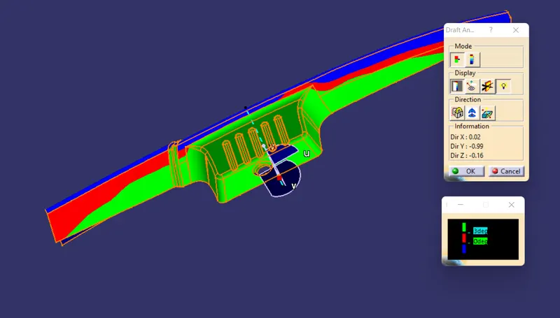
The Draft Analysis command enables you to detect if the part you drafted will be easily removed. This type of analysis is performed based on color ranges identifying zones on the analyzed element where the deviation from the draft direction at any point, corresponds to specified values.
so when we perform a draft analysis over a surface or on a component there will show 3 types of colour code, that is GREEN,RED and BLUE.
these three colours are corrospondes to the angle value present it that area.
If the colour is GREEN then the angle prensent in that are is 3 degree or mor than 3.
If the colour is RED then the surface having 0 to 3 degree andgle to the area.
If the colour is BLUE the the surface having the negative angle on that area.
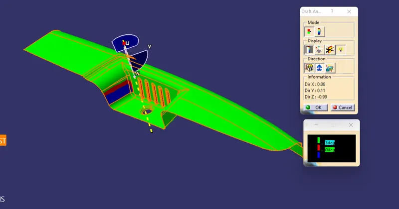
TOOLIND DIRECTION
in this part there is going to be two tooling direction one is Main tooling direction and second one is Side core direction
Mian tooling direction
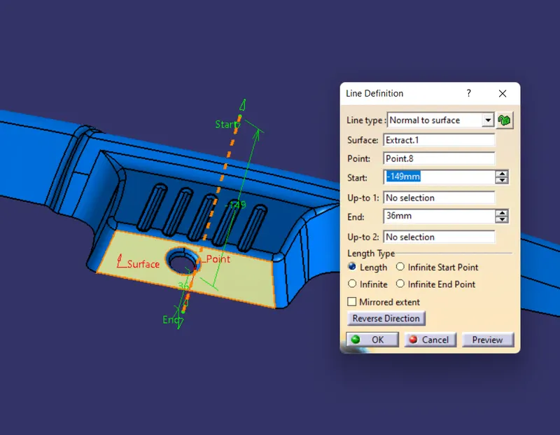
TO create the tooling direction extract the base surface from class a and create a point on surfcae.
then use line command select the line type as normal to surface selecte the extracted surface, select the point. and create the line.
this is goint to be our main tooling direction.
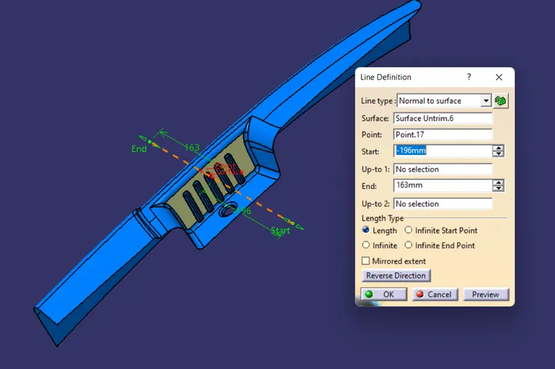
Side Core Direction
The purpose of side actions is to enable undercut geometryin other words, to mold parts that could not otherwise be made in a straight-pull mold. In straight-pull injection molding, the A-side and B-side of the mold open and the completed part can be removed by pulling it straight out of either side.
to create side core extract the one of bine sufrace which shown in the image bellow, create a point on the circle, then create line, use normal to surface command select the surface and select the point and cleate. this line use it as a side core direction.
DRAFT ANALYSIS CLASS A SURFACE
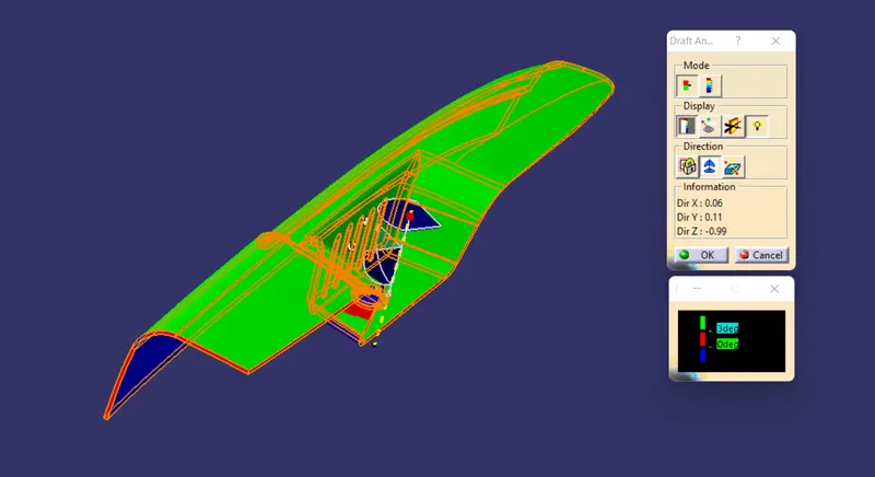
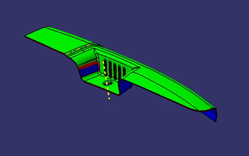
To perform draft analysis, switch view parameters in material mode, now unhide the main tooling axis open draft analysis and adjust the compass with the dooling axis now click over the surface and the draft analysis over the Class A surface as shown bellow in the images.
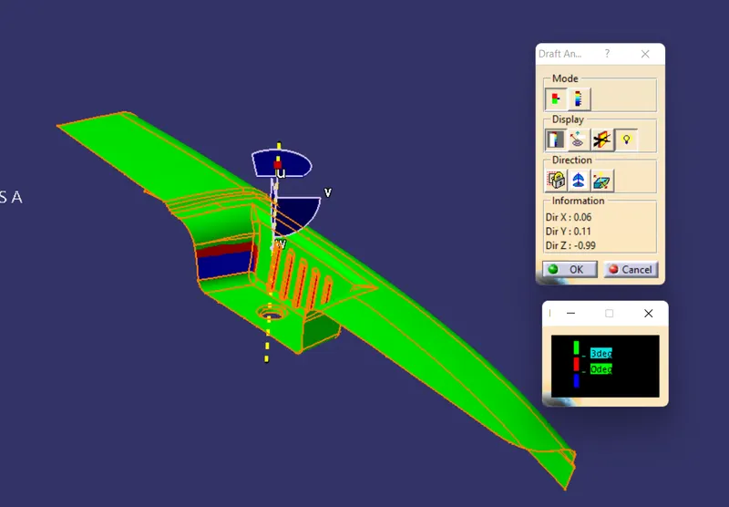
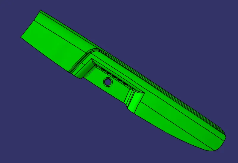
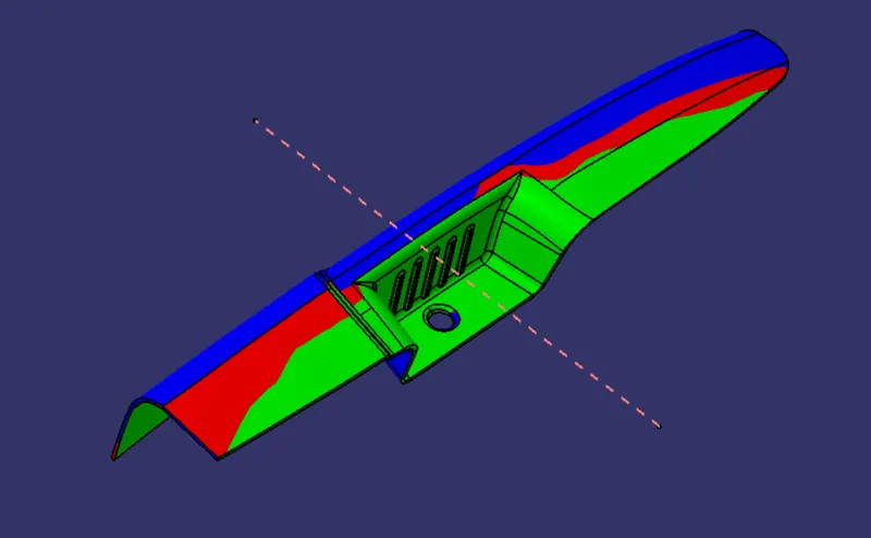
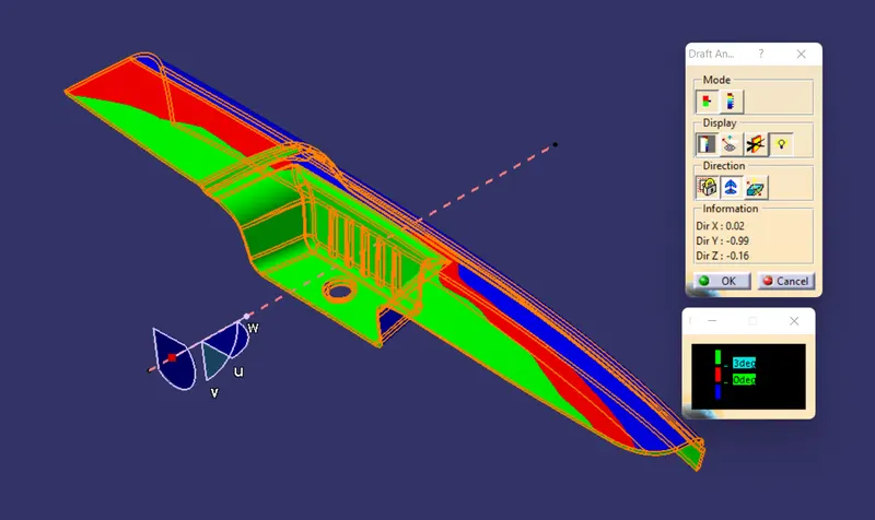
As you can see there is a blue clolour in the first images that called as undercut, so it can be cleared with side and i am creatind side care aslo for the rib
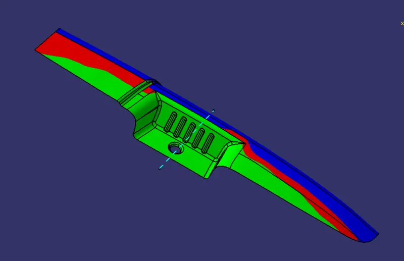
So the undercuts are cleared with the side core direction as see above.
B Surface Breation
lets make it not to messy so we created the B suface in many parts so it is become the very easy and handy design.
FIRST HALF
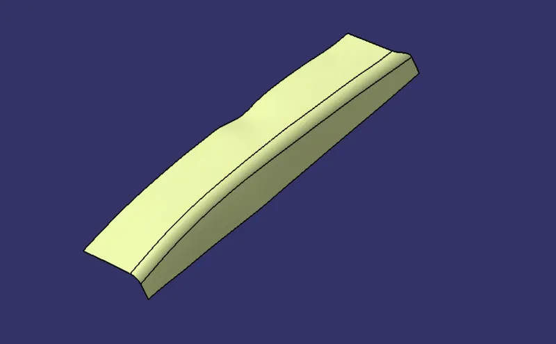
To create the first half extract the surfaces from the Class a surface which is over the top and side.
Untrim them. then offset it inside by 2.5 mm and then apply fillet.
So applying fillets is a very important thing when we create the class b surface, to create the component in prpoer manner.
so the filler over the class a surface is 17 so we have to do 17 - 2.5 = 14.5mm, apply to its edge.
SECOND HALF
same as the first half extract the surface from the class A surface. dont untrim them and offset them 2.5mm and the extract them so they can intersect each other.
then trim them together and then apply fillet, of 24.5mm.
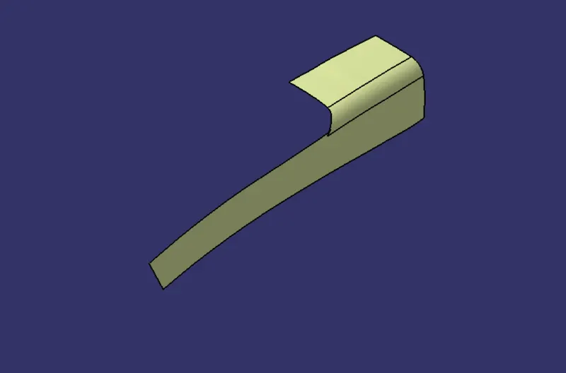
Connecting surface between the HALFES
To creat the connecting surface between the halfes ,e have to create a sketch at the filletsd are. because the the surface is covered with that fillets.
Create point at crossing points of the surfaces and the fillet as shown bellow
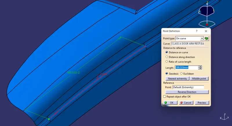
then insert the axis system at that point then sketch a inclined line in that sketch as shown bellow
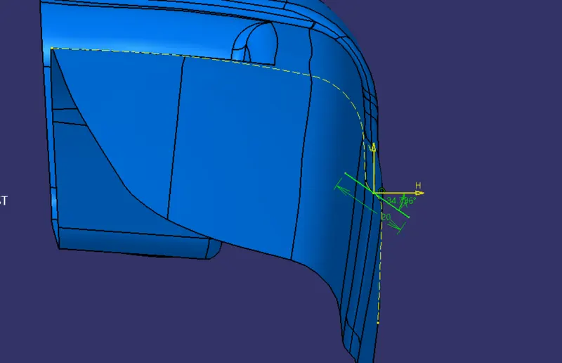
then extract he the edge of the filleted surface from the class A surface the use the sweep command use the sketch as profile and the extracted edge as curve.
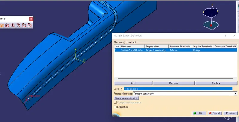
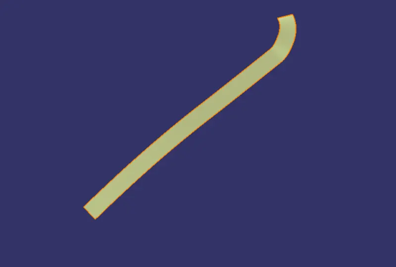
now create surface for the create conneting
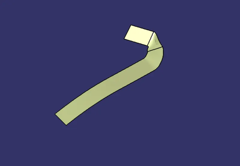
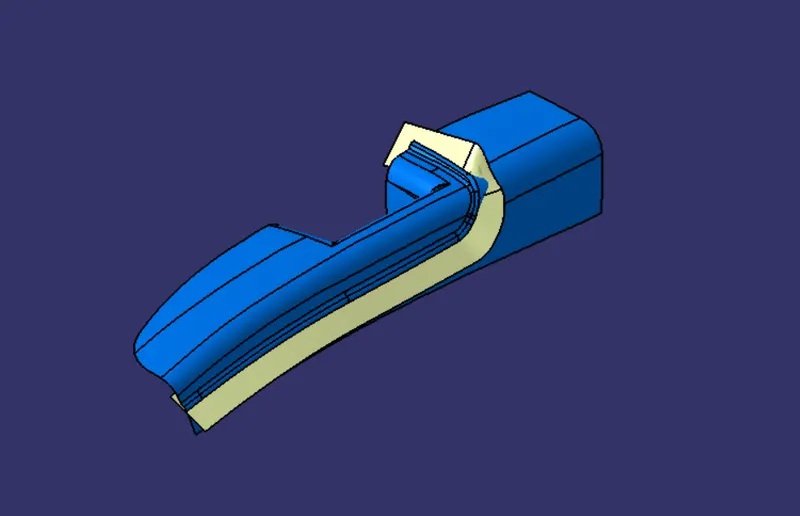
now trim the surfaces to each othe tho appropriate shape
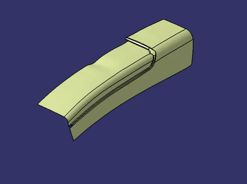
BIN WALLS
To create the bin walls extract the surface of the bin from the Class A surface. untrim them and extrapolate them then gove them a 2.5mm offset to otside then trim them them together.
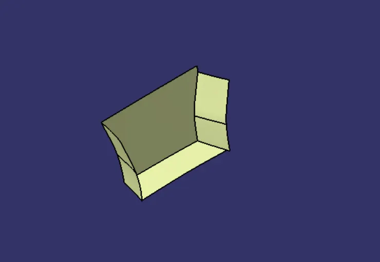
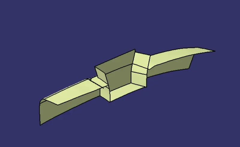
them trim the surface together to create the rquired surface as shown.
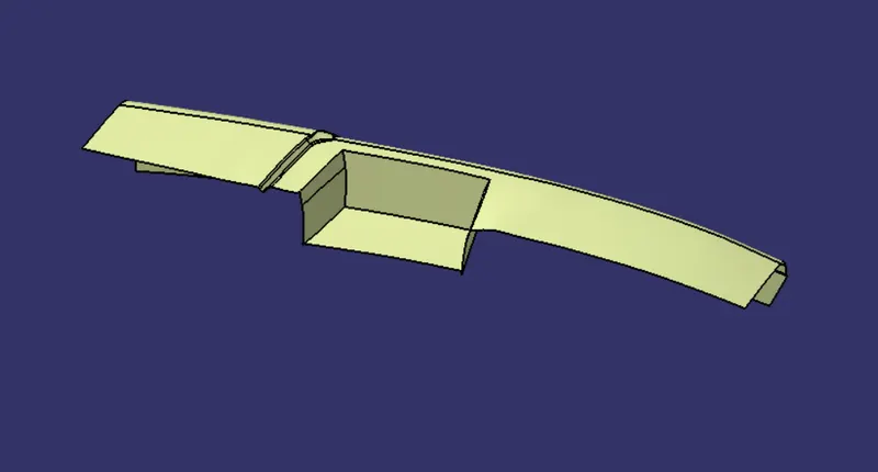
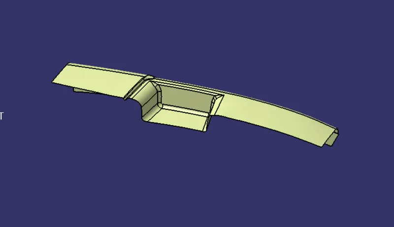
then apply fillets
CREATION OF C SURFACE
to create the surface extract the edge of the class A Surfae in a patches and then join them togater to get nice and unofrim Class C surface.
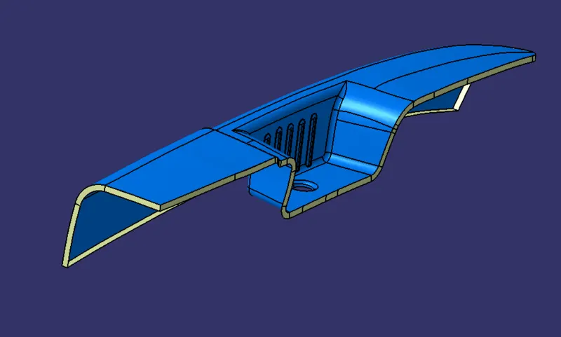
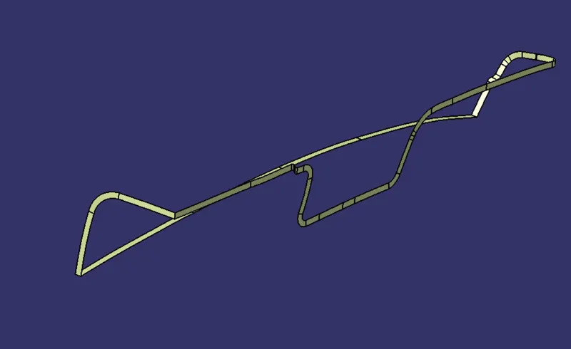
then join the join the calss A surface and C surface togeter then trim it with the class b Surfacet to create the required closed surface
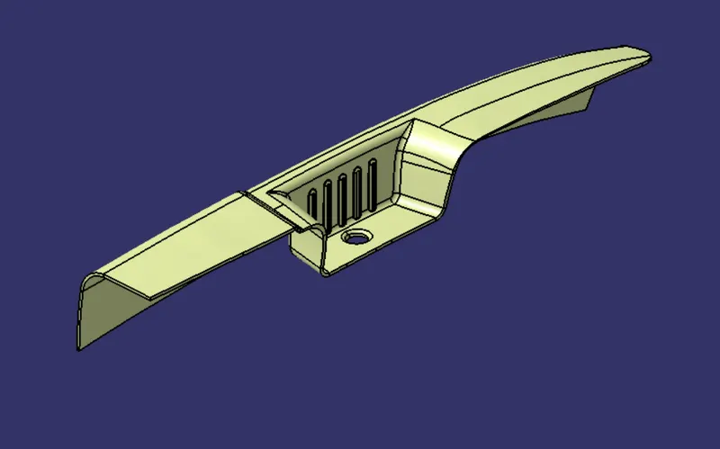
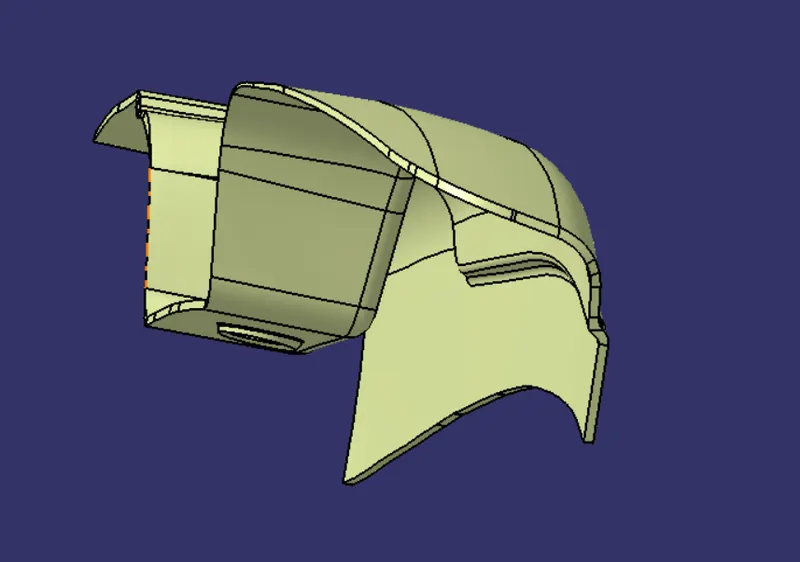
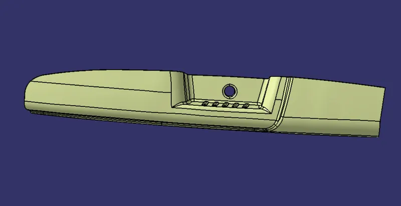
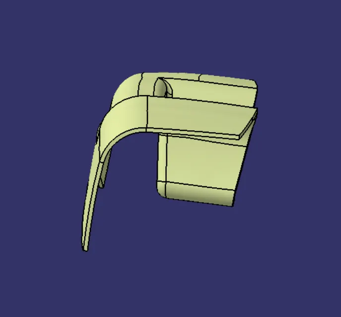
CREATE OF CLOSE
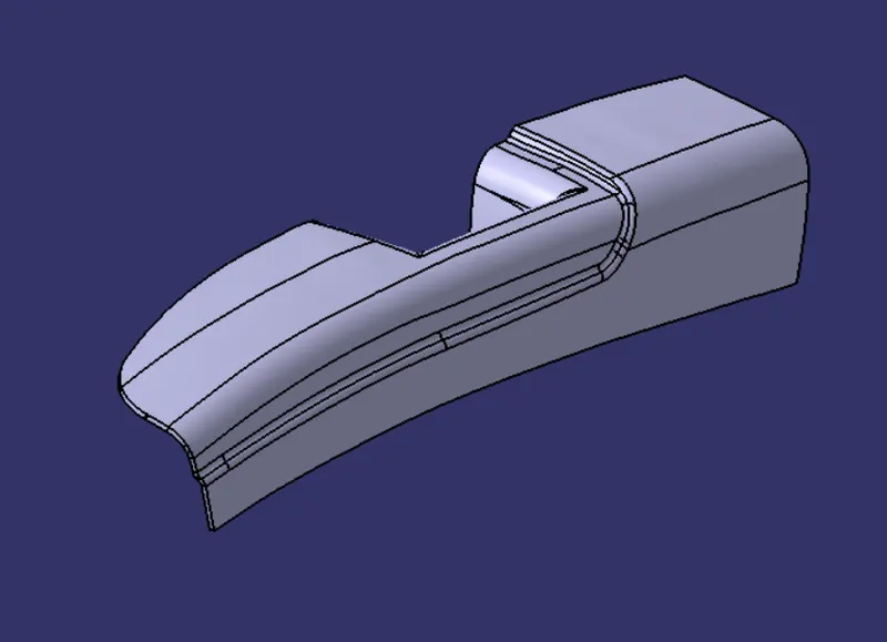
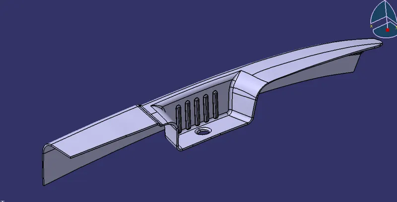
DRANFT ANALYSIS
FROM THE MAIN TOOLING DIRECTION
SIDE COIRE DIRECTION
TREE STRUCTURE
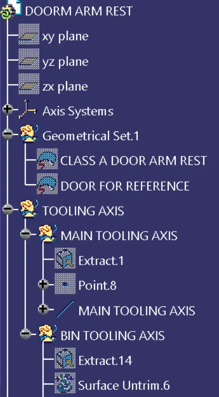
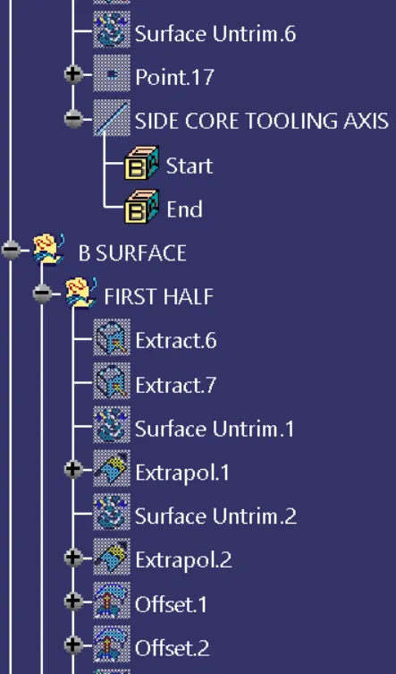
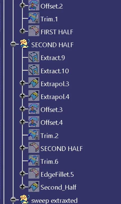
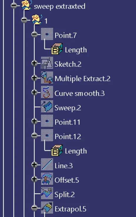
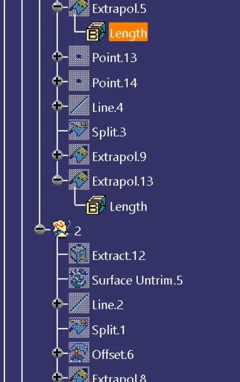
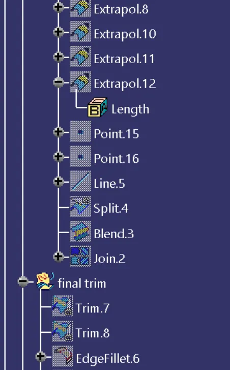
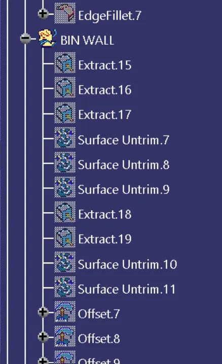
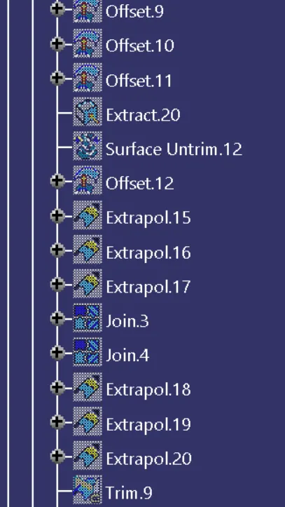
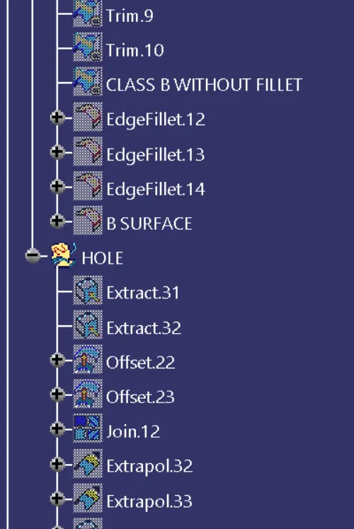
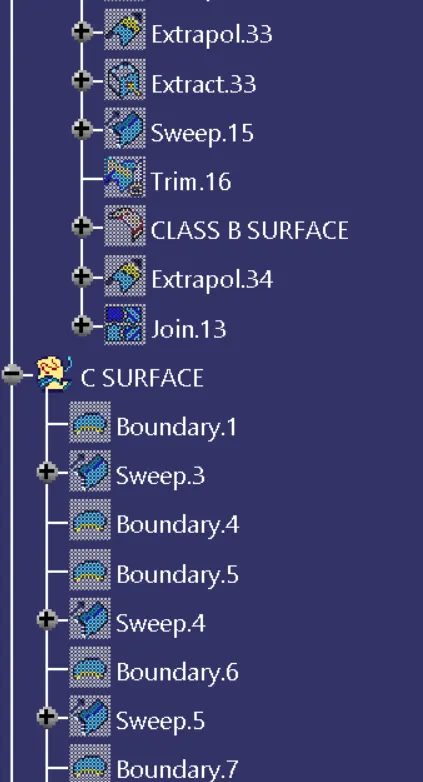
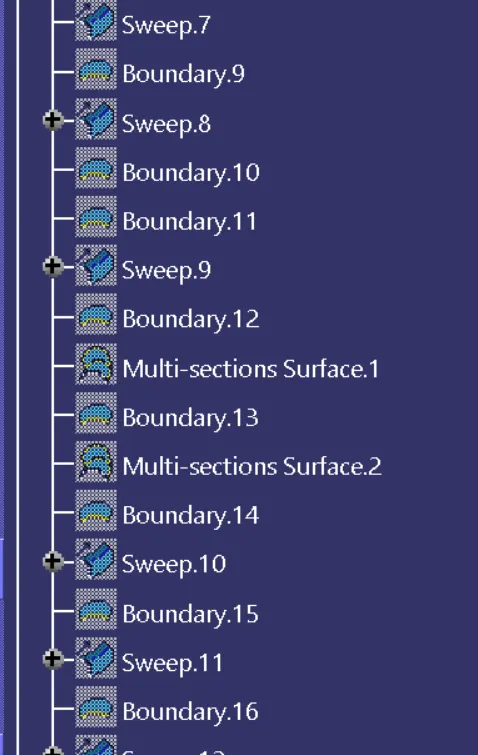
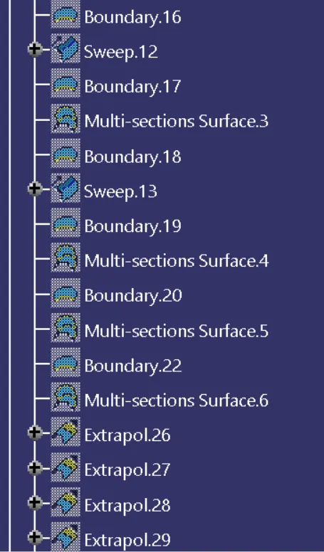
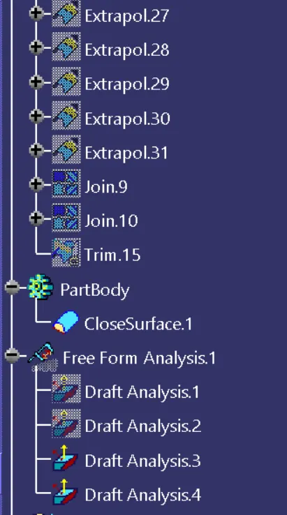
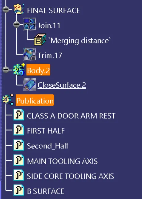
I HAVE DID MANY TRIALS AND ERROR TO CREATE THIS COMPONENT THAT WHY MY TREE STRUCTURE IS THAT MUCH LONG