Door Arm Rest Week 8 Challenge
Views:
Isometric view:
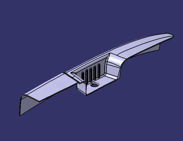
Front view:
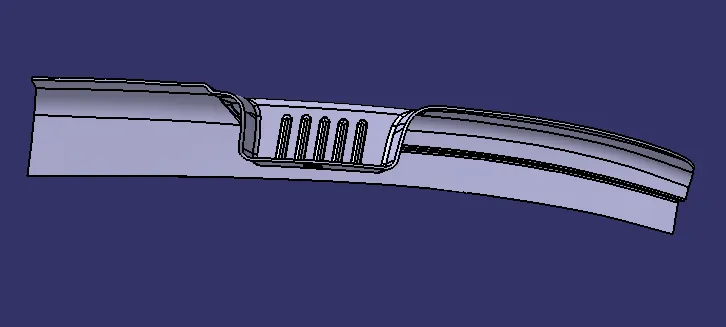
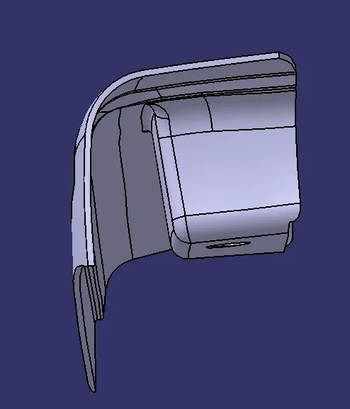
Side view:
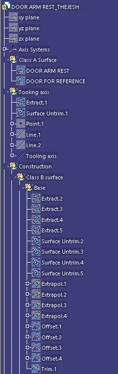
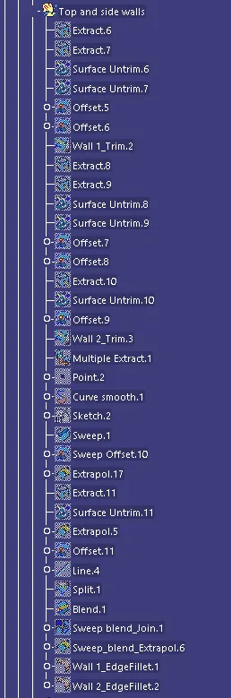
Modal tree:
Tooling Axis Creation:
The tooling axis has been created normal to the base surface, maintaining a minimum of 3 deg draft across the side walls. This was created using a 3D line and adjusted through Angle/ Normal to curve option.
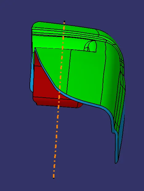
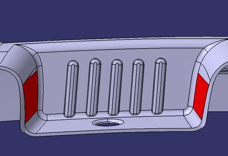
There is some curved section at the sidewall which may cause some issue on draft analysis which should be controlled using side core along Y-axis direction as shown below.
Modal creation:
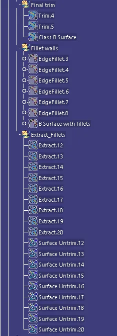
The modal is built using the provided Class A surface and the individual surfaces were extracted, untrimmed, and extrapolated. The final surface is offset to 2.5 mm to match the final part thickness. All surfaces were created using the same procedure and they were trimmed, blended, and added required fillets to finalize the Class B Surface.
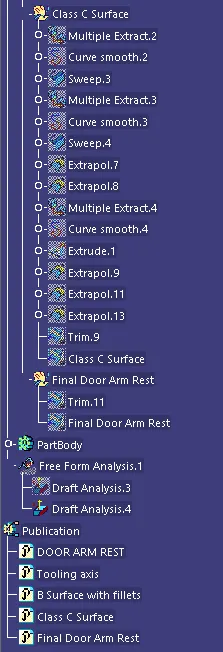
The Class C surface is created using the Sweep along the tooling axis. The sweep is done at the exterior ends which forms the thickness of the part. The edges of Class A Surface are multi extracted and they are smoothened using a smooth curve option. The curve is used as a guide curve and the profile for the same is swept.
The final trim is made by trimming all the Class A, Class B, and Class C surfaces to make the final door armrest.
Draft Analysis:
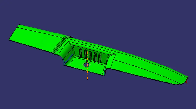
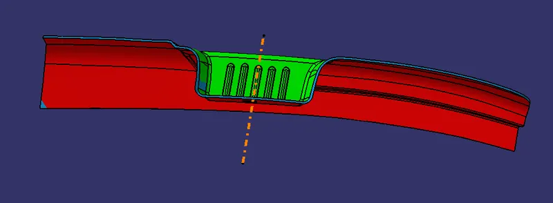
The draft analysis is done along the tooling axis. The axis through which the core and cavity need to be designed has been analyzed and then the part is built. The axis is added and the part is selected to run the analysis and the surfaces plotted green accept the designs and the surfaces marked red and to be checked and need to be taken care of. The surfaces in blue are the ones with no draft which need to check.
Some surfaces marked blue need a separate tooling axis and the surfaces marked red are under another side of the tooling axis which is ok to move. The results of the same are plotted below.