Door Arm Rest Week 8 Challenge
DOOR ARM REST DESIGN USING CATIA V5
Aim
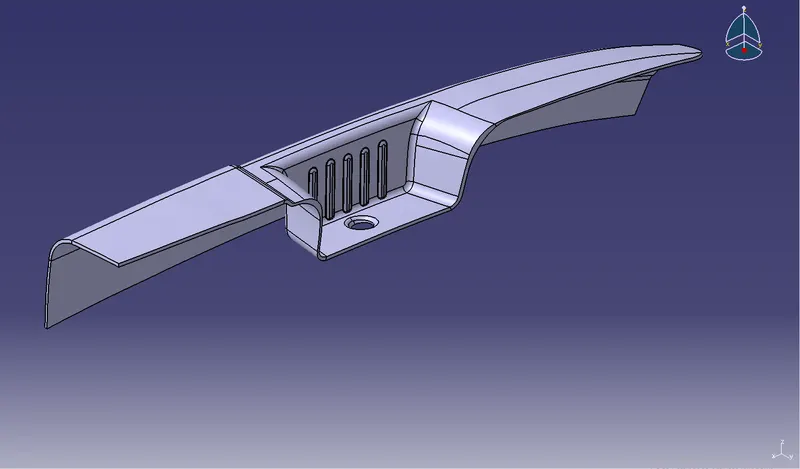
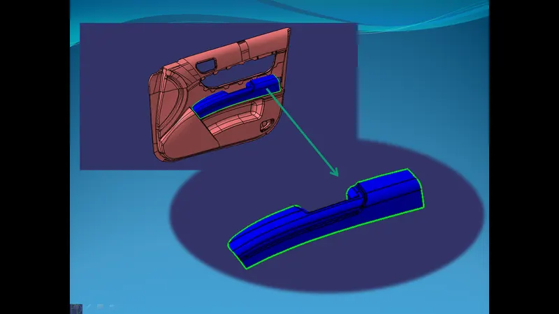
In this project, we will design Door arm rest from Class-A input using Catia v5.
- Will check whether the Class A faces that intersected will clear the direction based on the tooling axis.
- Later we will start working on the Draft Analysis tool to check whether our tooling direction clears the path for easy removal of material from the tool.
- Class B creation using extract, untrim, extrapolate and offset tools from Generative Shape Design Workbench.
- Class C creation using sweep command.
- At the final stage, we will convert it into a solid inside part workbench and perform Draft Analysis.
DOOR ARM REST -
1 - We will receive the A surface as our input .
2 -For creating main tooling axis , we will first extract the base and then untrim it. we will then add a point onto that surface at 0. we will then add a line from the point and normal to the untrimmed surface .
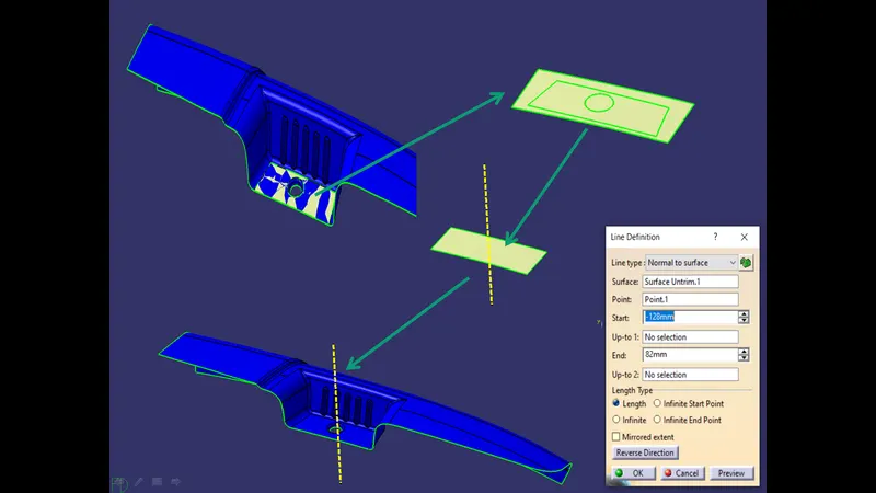
3 - For creating side core axis , We will extract the side face and then add a point on the surface at 0. we will then add a line normal to the surface .
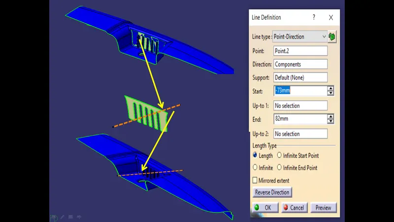
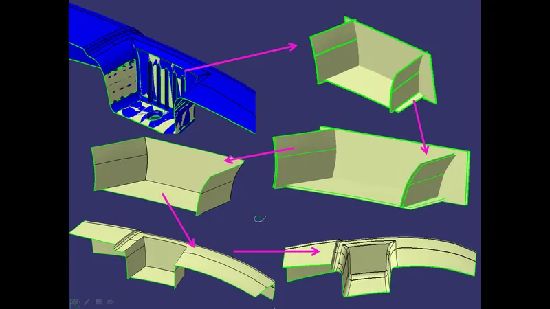
4 - Now we will start with creation of B surface . we will extract the faces as shown below , then will untrim it . we will join this two surfaces together .
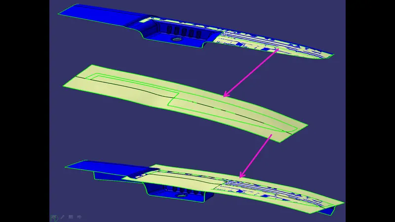
5 - We wil extract the back surface , we will extrapolate it on one side .
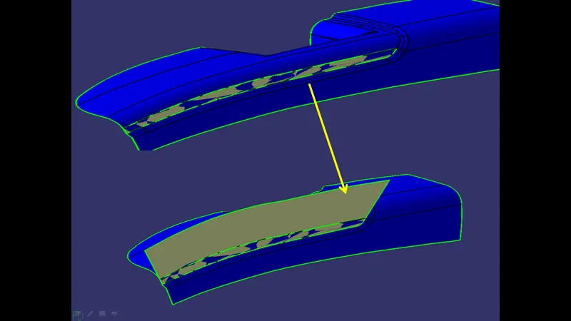
6 - Now we will offset these two surfaces with a value of 2.5mm . we will then trim the offsetted surfaces together . then we will add a fillet as per the requirement following design rule .
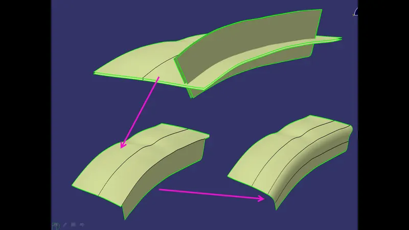
7 - We will extract the faces as shown below , we will then extrapolate it from one side only so that they meet each other . we will then trim it together and add a fillet to it .
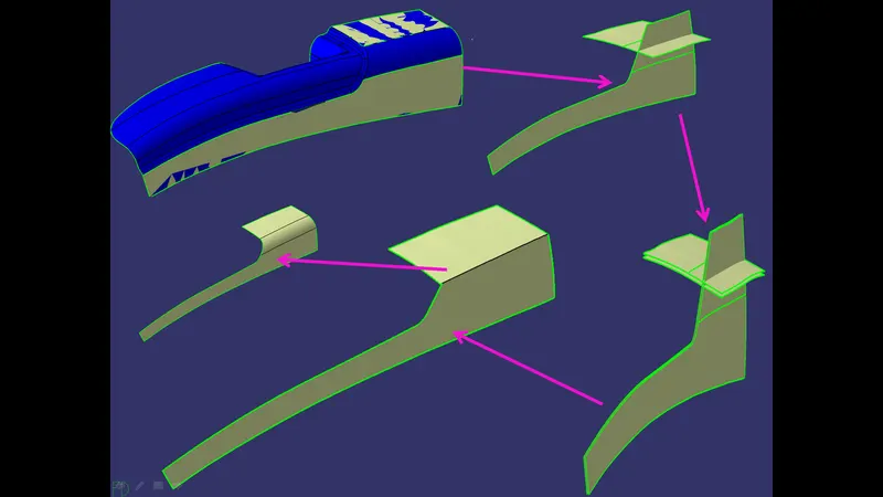
8 - For the connecting surface , we will place a point on the edge where the two fillet surfaces meet . then we will add a axis onto that point and start a sketch on it . we will draw a line which will be tanget to the fillet . we will then extract the boundary line between the two fillet , this will act as our sweep path . we will use the sweep tool to getbthe required surface . we will then offset it by 2.5 mm .
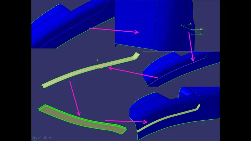
9 - We will extract the face as shown below . we will untrim this face and offset it for a value of 2.5 mm . now we need to connect this surface with the sweep so first we will add a line onto this surface at a angle , this will help in the blend operation . we will spilt this surface with the line ,below is how we will get the surface . we will then use the blend tool on the sweep and the split surface .
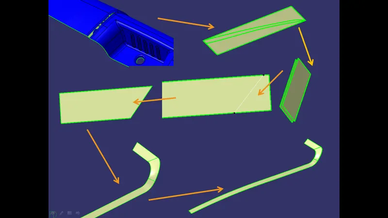
10 - We will trim this surface with the other two surfaces that we had developed . we will add a fillet as per the design rule .
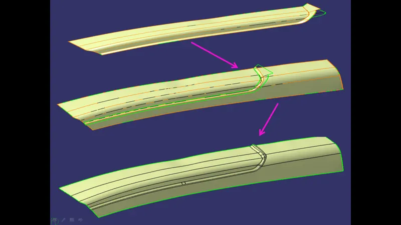
11 - We will now extract all the surfaces from the basin. we will untrim them add a offset of 2.5mm to them and then trim the offsetted surfaces together . we will then trim this surface with the main surface and add a fillet to it .
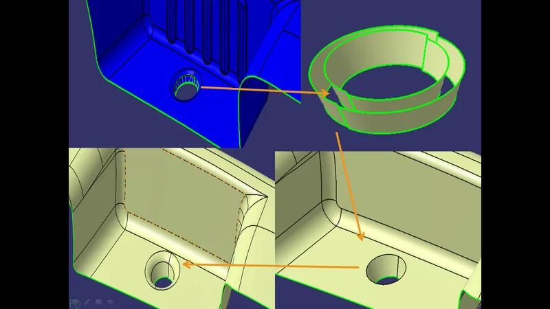
12 - We will then extract the faces of hole , we will untrim them and then offset them at 2.5mm . we will then trim this offsetted surface with the main surface and add the fillet to it .
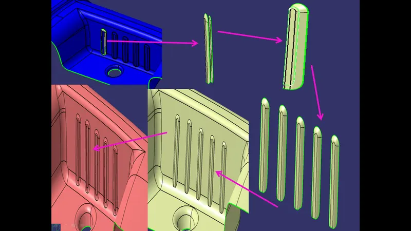
13 - We will then extract the slot faces with multiple extract . we will offset it by 2.5mm then we will extrapolate this surface for 5mm . we will then do this procedure for the remaininf slots . after that we will trim these slots with the main surface . we will add a fillet to it . this will be our b surface .
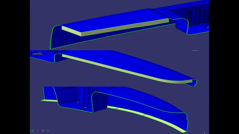
14 - We will then start creating C surface , for this we will create sweep in main tooling axis direction with 3 degree value for all the faces as shown below . but for back face we will create sweep at a 90 degree angle .
15 - For the irregular shape surface we will create it using mss tool . first we will add a line with help of points on the surface as shown below . we will then trim the surface with the line , similarly we will do this procedure on the second sweep . we will extract the boundary which we want as the path . we will then use the mss tool and join this two surfaces together .
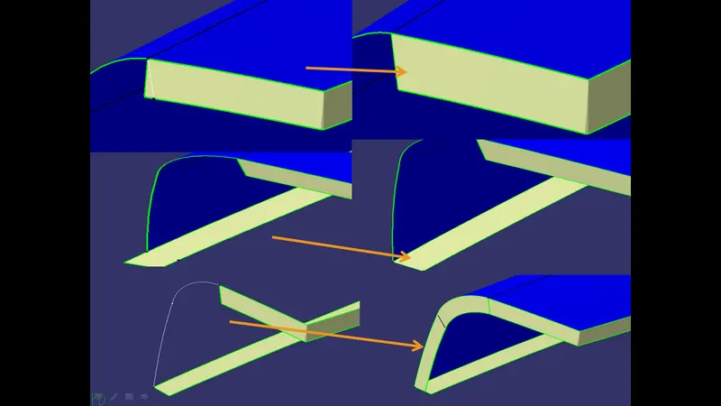
16 - Similarly , we will use the mss tool to create the remaining surfaces . once this is done we will join these surfaces with the A surface .
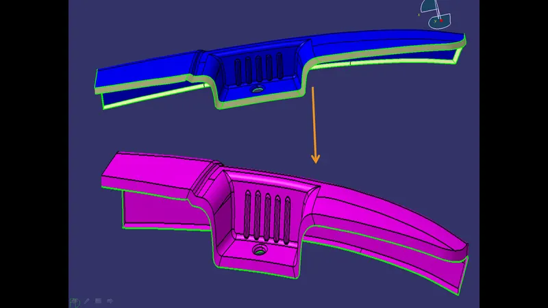
17 - We will now trim this surface with our B surface . We will get our final DOOR ARM REST surface . We will then switch to part body workbench and create a closed body for the surface .
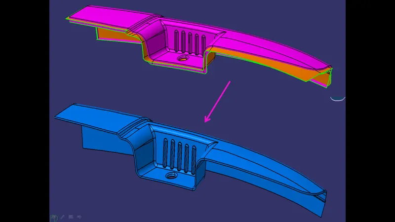
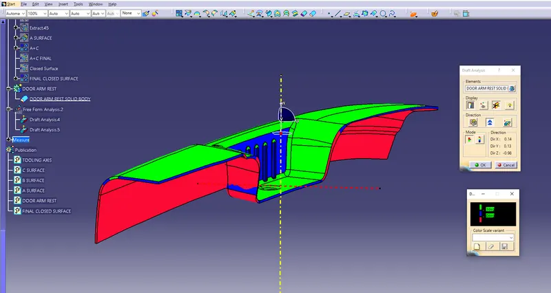
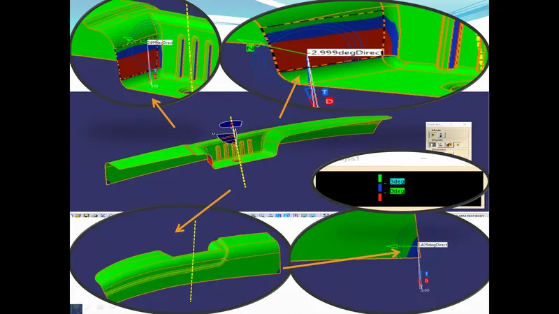
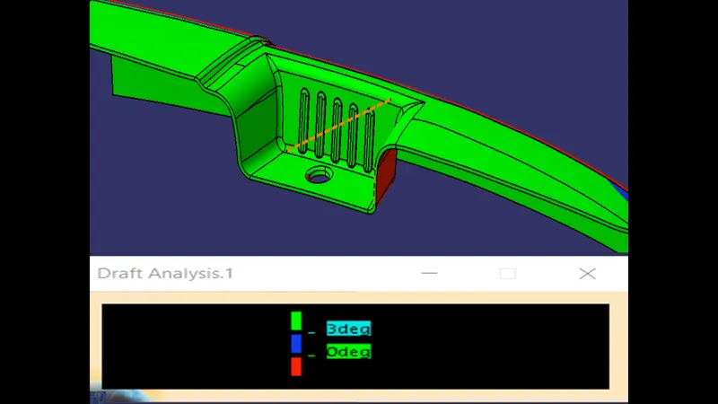
18 - Below is the draft analysis report on the A surface with main tooling axis .
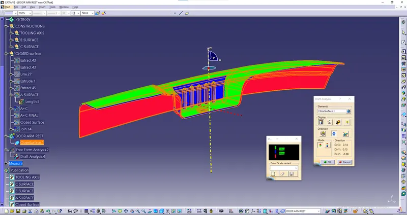
as we can see most of the surfaces are green which means they will clear in main tooling direction . but for the basin part we see some surfaces with red color . this means that it will not clear in main tooling axis so this is the reason we create the side core axis .
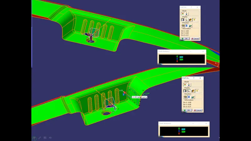
19 - As we see below , the basin part in the A surface clears in the side core tooling axis .
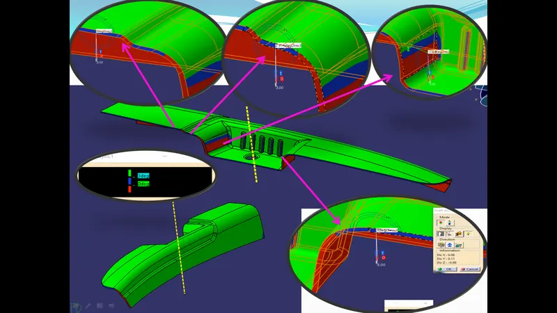
20- Below is the draft analysis of the Door arm rest body . as we see that most of the faces clear in the main tooling direction . there are somes faces with red color . this will be cleared in side core axis direction .
21 - Below is the draft analysis of the Door arm rest body in the side core axis direction .
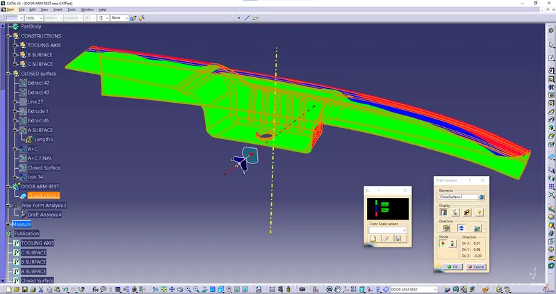
Final solid Body ( Door Arm Rest )