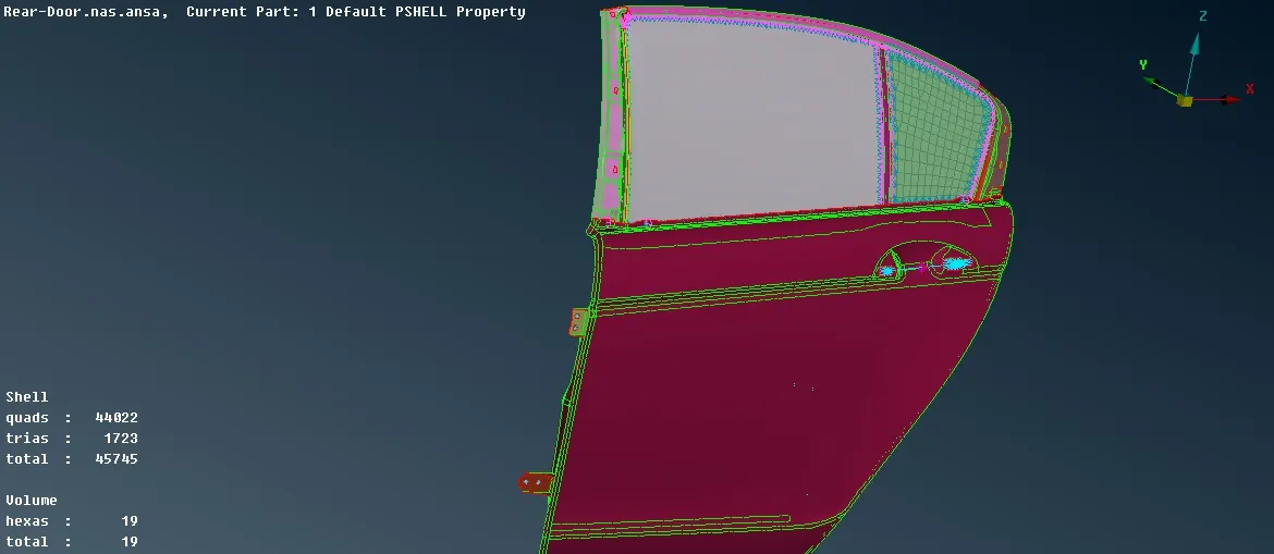
Developing Connections on a Rear Door model of a car using ANSA preprocessor
Developing Connections on a Rear Door model of a car using ANSA preprocessor
- Aim
create suitable connections for the given rear door FE model, using different types of connection techniques along with different 1D elements.
- Procedure
1) open the Nastran deck file as, File > Input > NASTRAN > Open
2) create different PID for the rear door components so that it will be easy to select appropriate parts while creating connections.
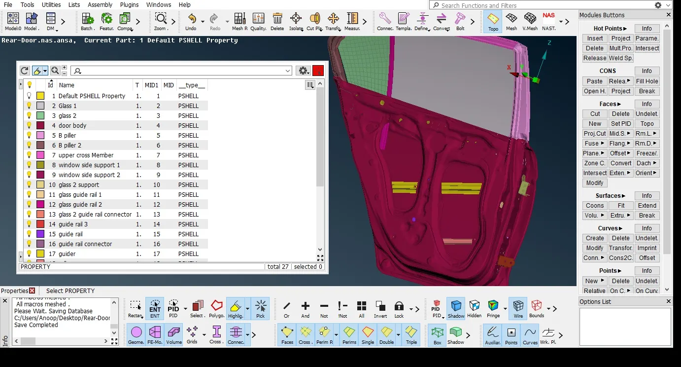
3) Different types of connections
- Bolt connection
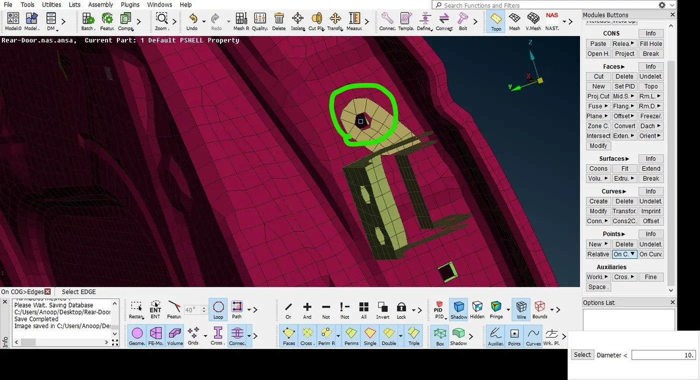
In order to create Bolt connection between different parts first we need to create 3D points on the COG of the holes using Topo Module > Points > On COG select the inner perimeter of hole
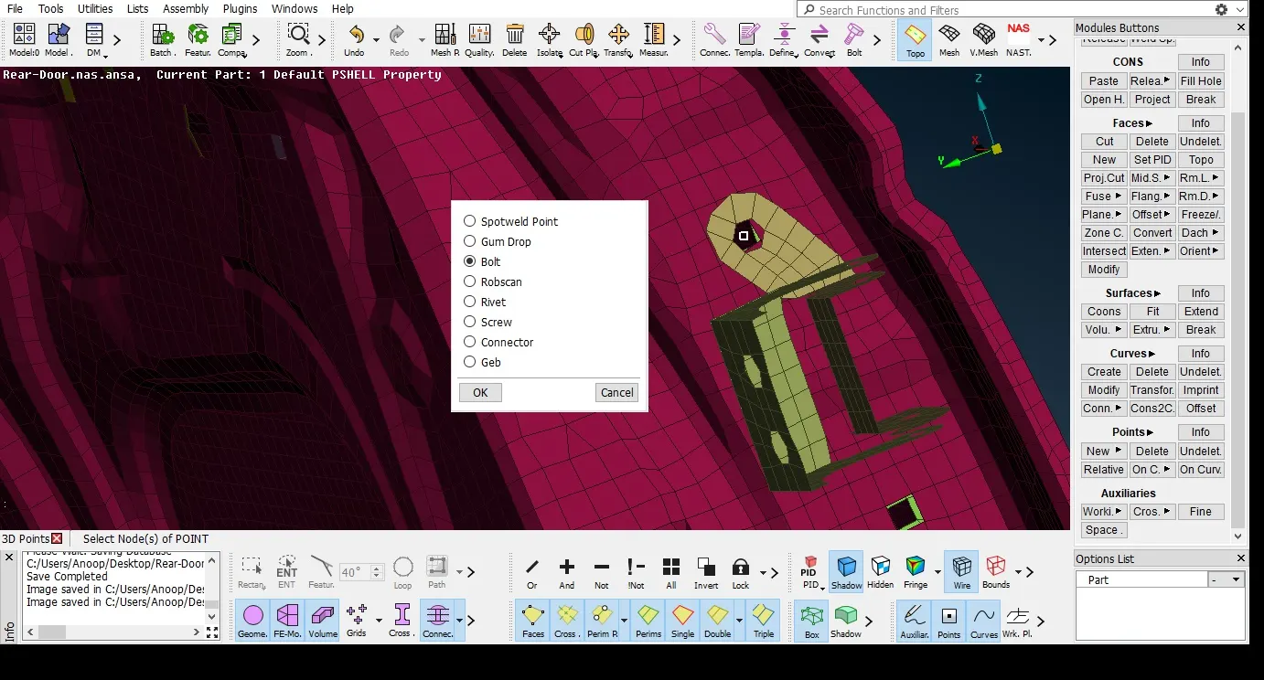
Convert the 3D point created into a Bolt connection using Assembly > convert > select the 3D point > select Bolt connection > ok, 3D point is converted into a Bolt connection.
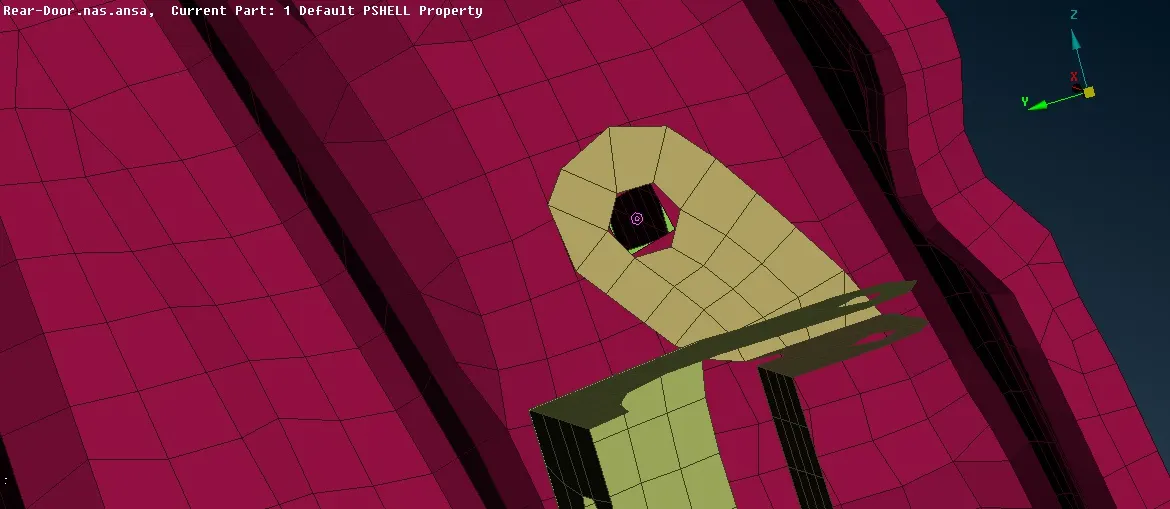
Now we have to Realize the Bolt connection. Goto Assembly > Connection Manager > selection assistant window appears > select the Bolt connection created > Middle click to confirm > Connection Manager window opens.
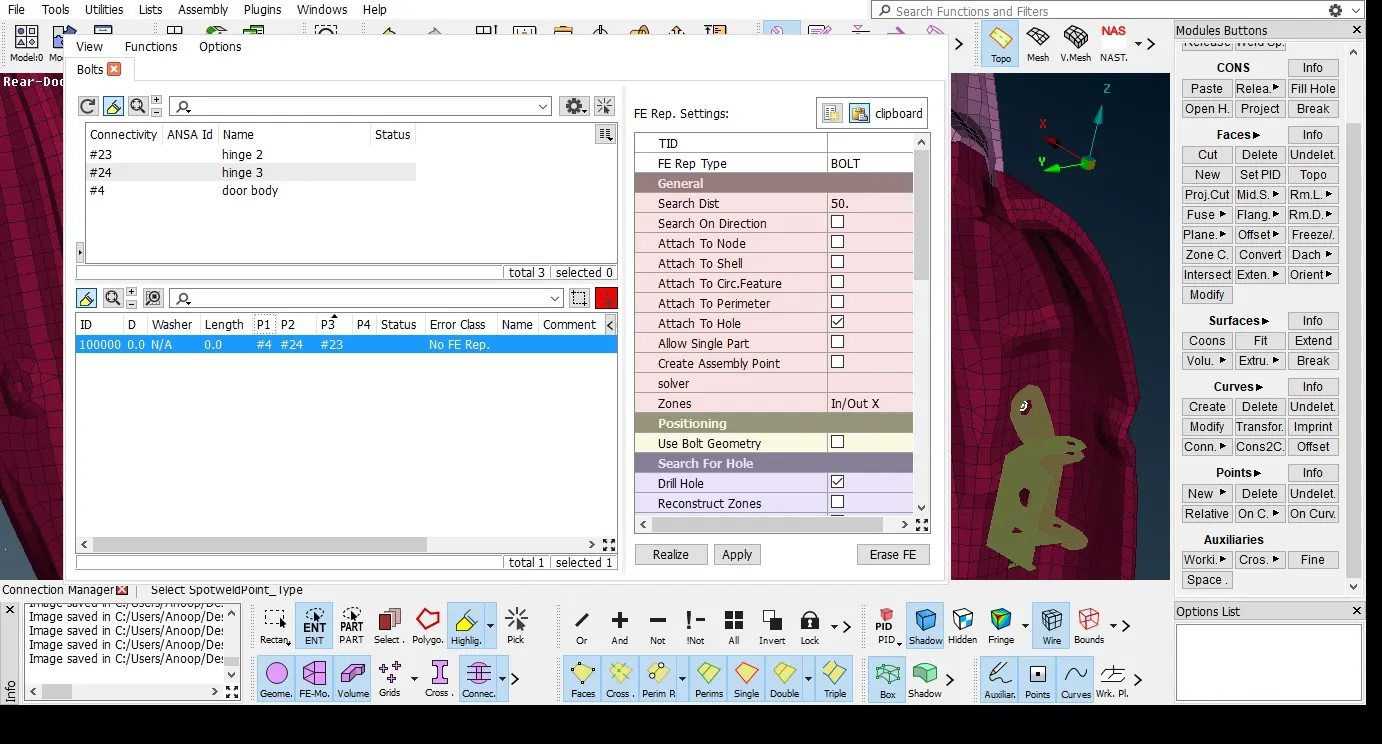
Define the parts to be connected by right-click on P1, P2 > Modify > press F1 on keyboard and select the specific part from GUI.
Select the FE representation type as BOLT > Apply > Realize
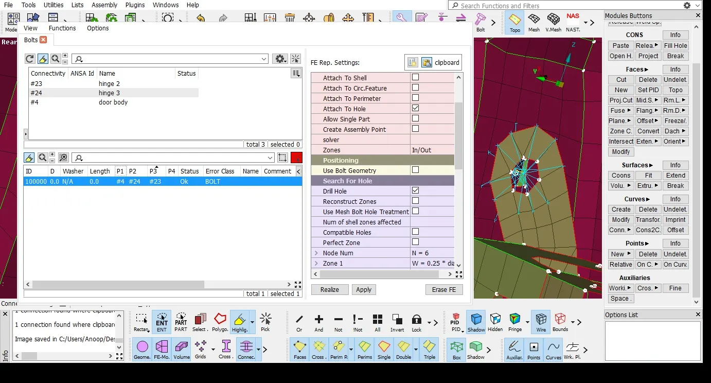
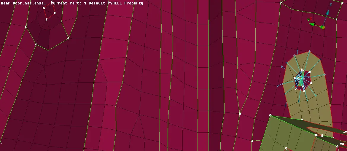
- RBE2 Element representation
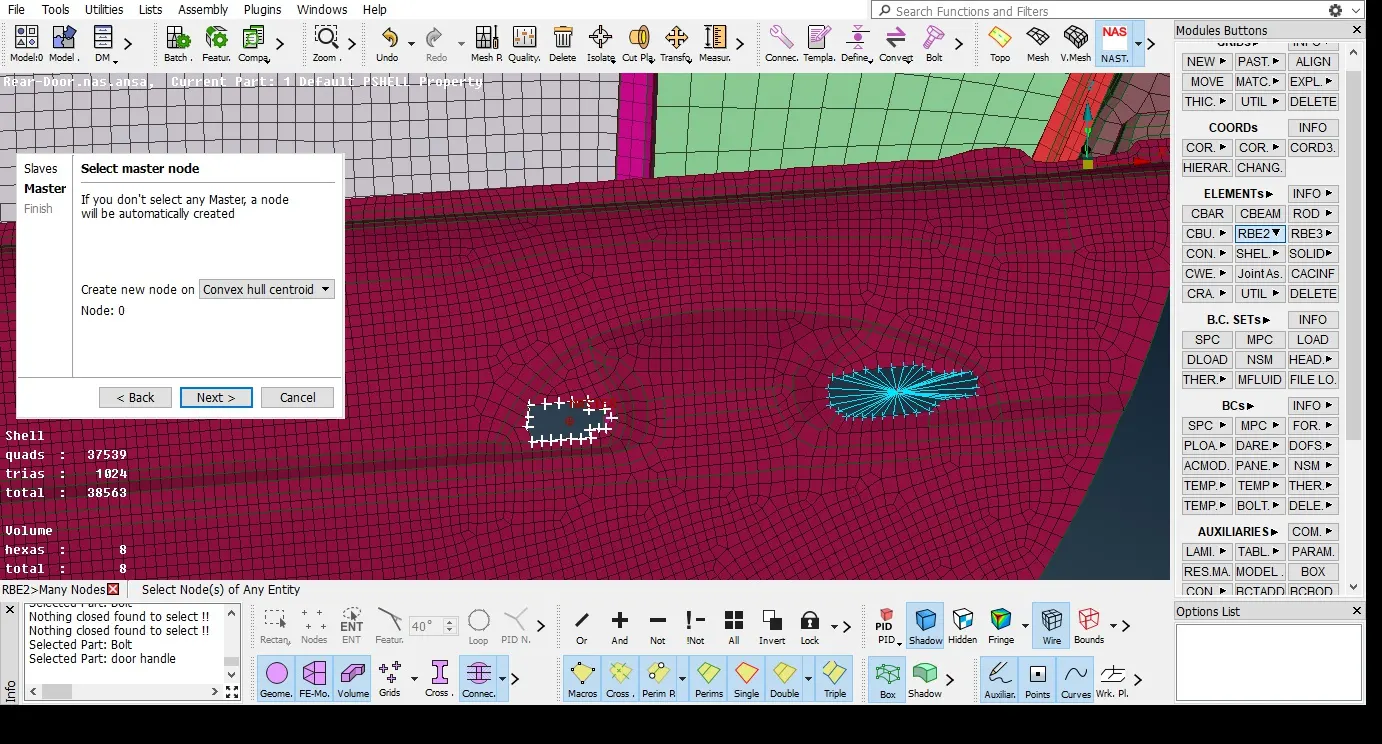
we can also represent the bolt connection as RBE2 Element. Go to NASTRAN Deck > Elements > RBE2 > Many nodes> select the slave nodes as the nodes of inner perimeter of hole by Loop selection tool > Master node will be created at the centre of hole > ok > Finish. Thus a RBE2 cluster representation will be created.
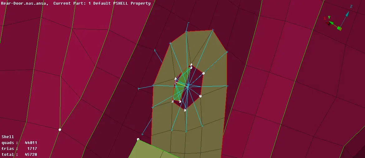
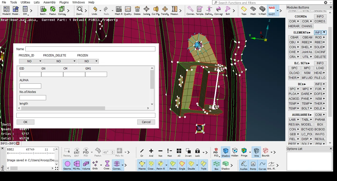
Created a 2 Node RBE2 Element for the hinge of the door where door will be pivoted using NASTRAN Deck > Elements > RBE2 > Two nodes
Inorder to allow the opening and closing movement for the door we have to remove the rotational z-axis d.o.f (6) for the two node RBE2 element created. Go to NASTRAN Deck > Elements > Info > select the 2 node RBE2 created > property window opens remove the 6th d.o.f in CM tab.
- Spot weld connection
Inorder to create spot weld connection between two parts first create 3D points on one of the parts using Topo Module > Points > On COG
Convert the 3D points into spot weld connection using Assembly > convert > select the 3D point > select spot weld connection> ok
Now we have to Realize the spot weld connection created. Goto Assembly > Connection Manager > selection assistant window appears > select the spot weld connection created > Middle click to confirm > Connection Manager window opens.
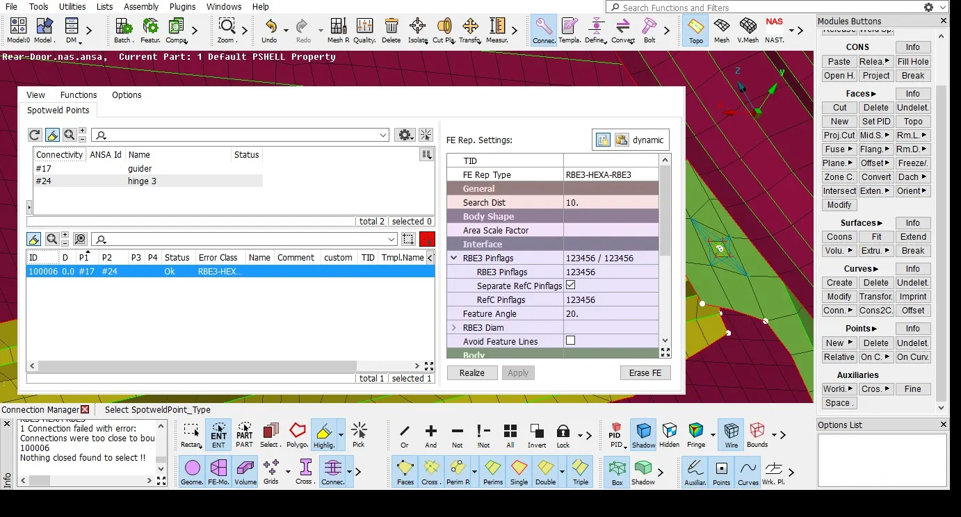
Define the parts to be connected by right-click on P1, P2 > Modify > press F1 on keyboard and select the specific part from GUI.
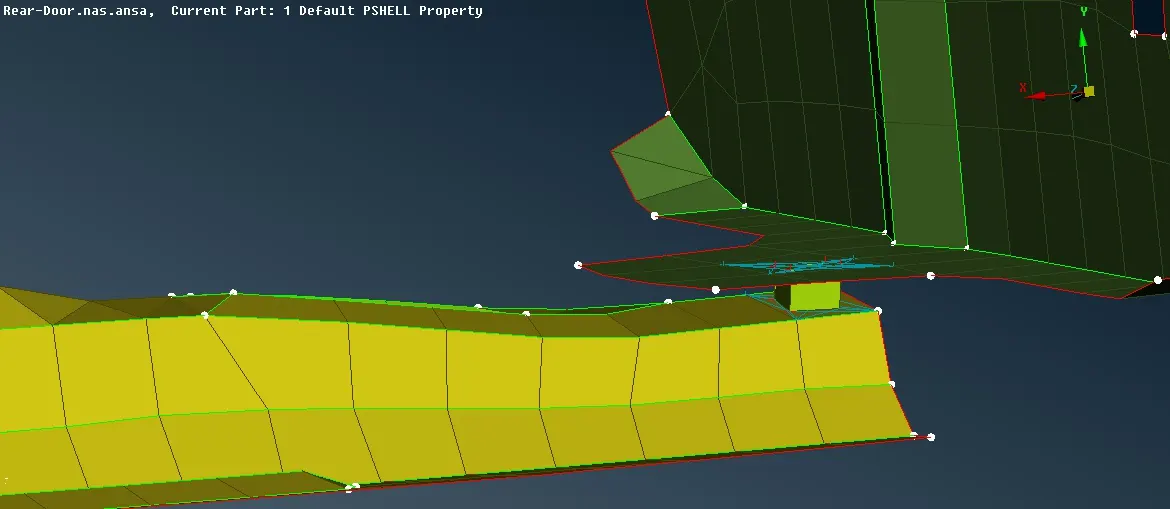
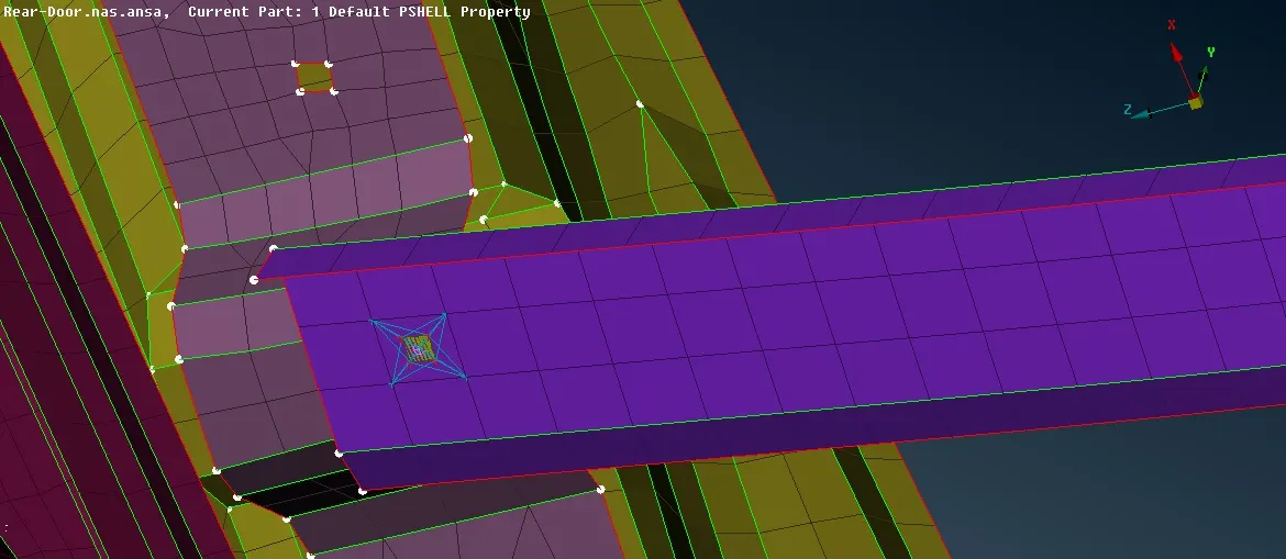
Select the FE representation type as RBE3 HEXA RBE3 > Apply > Realize
- CON Mass Element representation
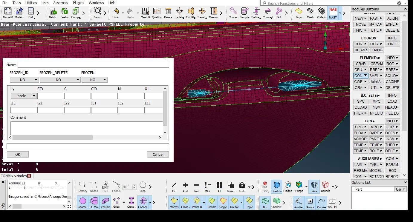
Door handle will be represented as a CON Mass element.
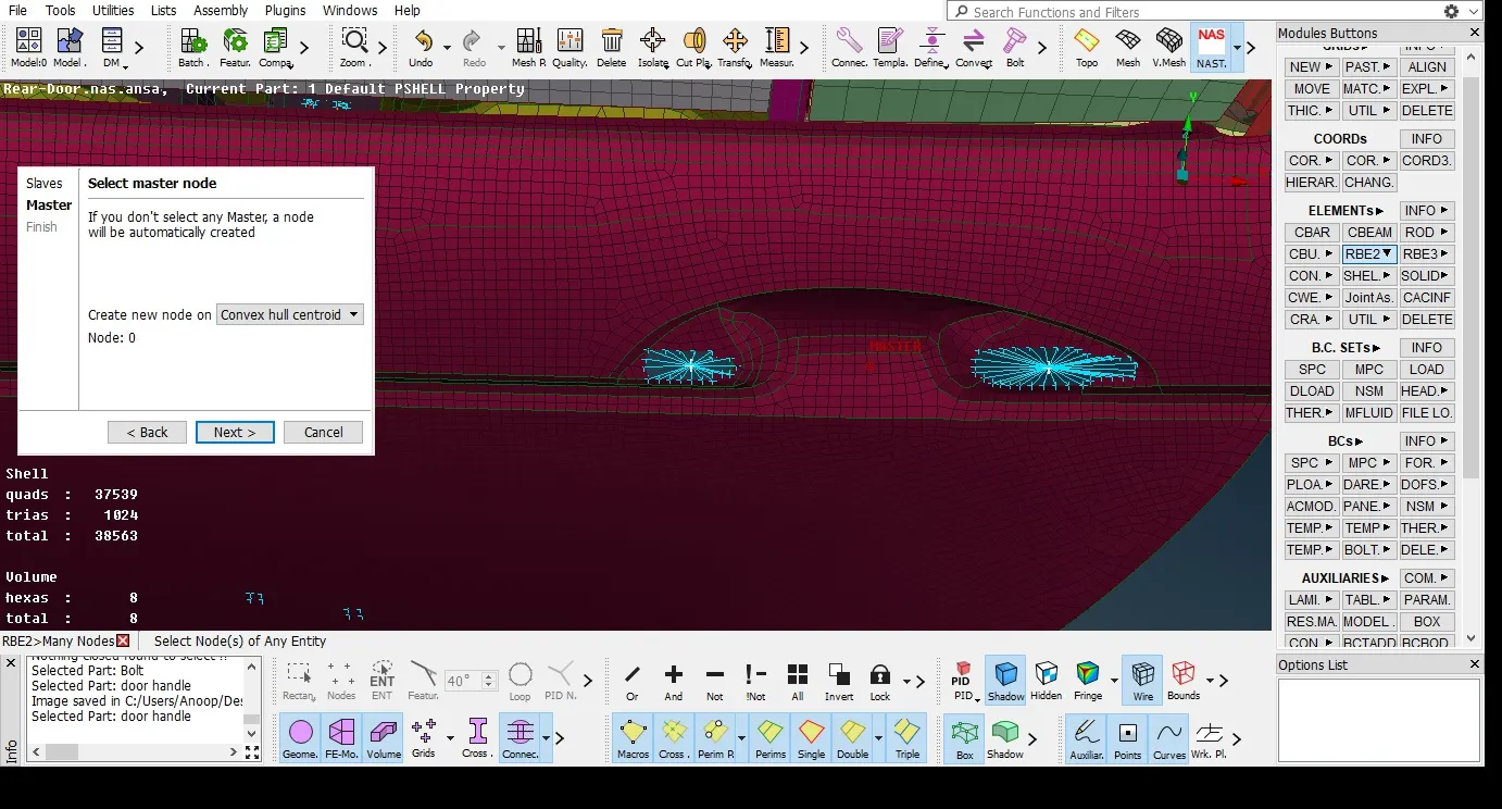
In order to do that first, we have to rigidised two holes the door handle using RBE2 element and then create a RBE2 > Many Nodes element between two master nodes of the cluster RBE2 created in 2 holes.
Then we have to assign a CON Mass to the master node using NASTRAN Deck > Elements > CON Mi > CONM2 > Nodes > select the master node > Middle click to confirm > property window opens > Enter the mass of door handle in tonnes.
- CBUSH Element representation
To create a connection between window glass and weather strips (black rubber cushion holding the glass) we use CBUSH Element.
Inorder to create CBUSH Element first we need to create curves from the FE of glass using, Mesh module > Perimeters > Feat 2 curve > select the edges of glass FE > middle click to confirm.
Convert the curves into spot line connection lines. Using Assembly > convert > select the curves created > select spot line connection > ok,
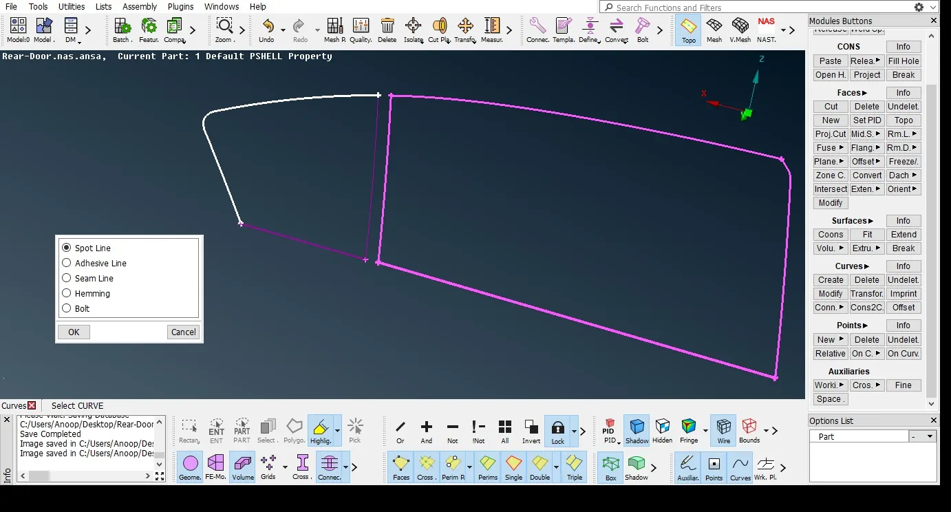
Now we have to Realize the spot line connection created. Goto Assembly > Connection Manager > selection assistant window appears > select the spot line connection created > Middle click to confirm > Connection Manager window opens.
Define the parts to be connected by right-click on P1, P2 > Modify > press F1 on keyboard and select the specific part from GUI.
Select the FE representation type as RBE3 CBUSH RBE3 > Apply > Realize
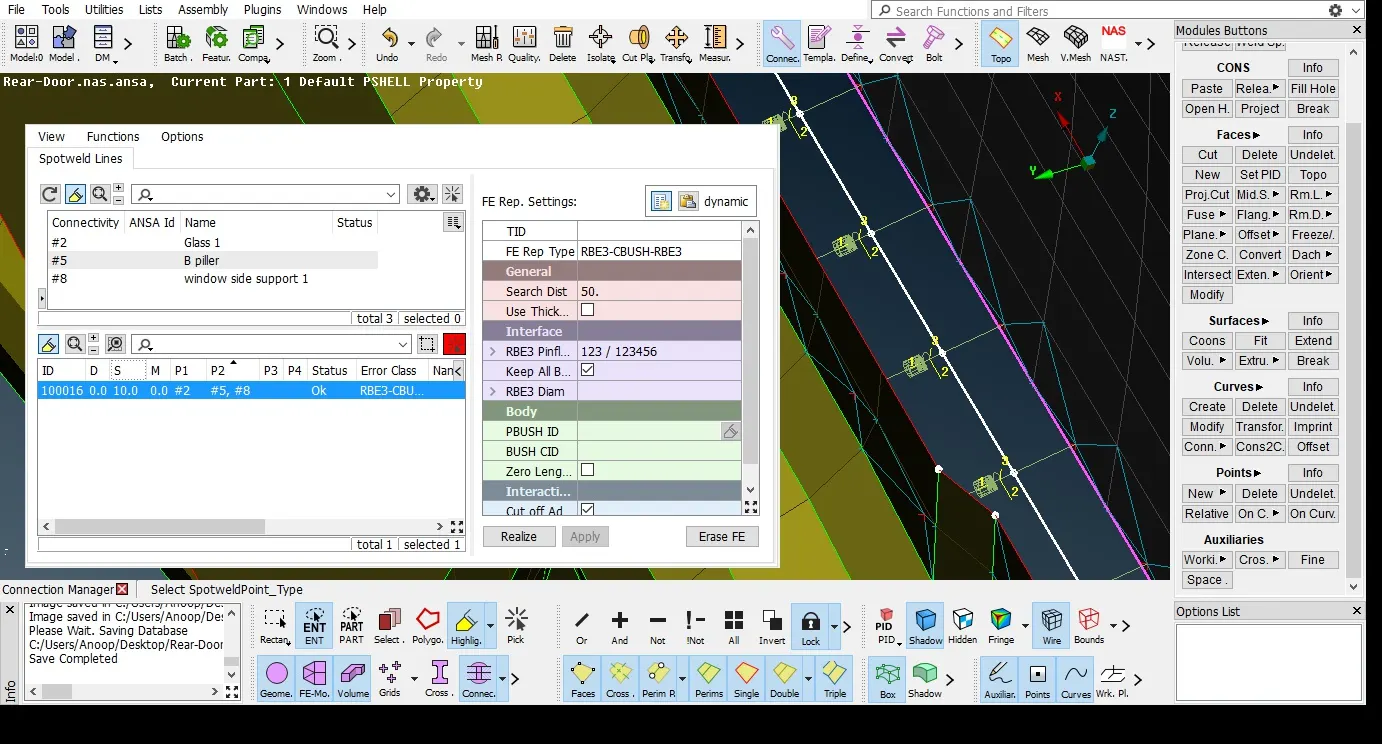
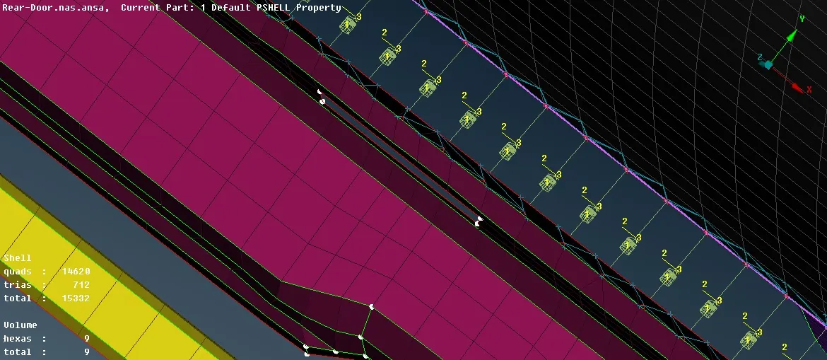
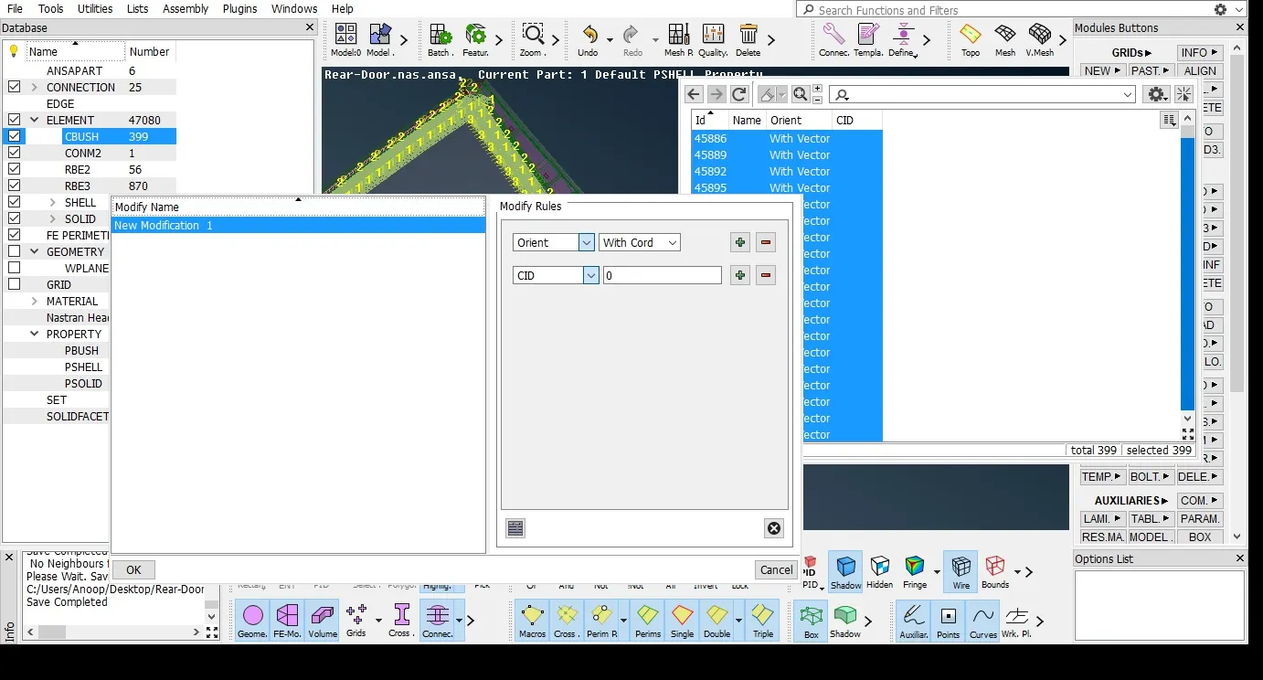
CBUSH Element has been created, inorder to change the orientation of CBUSH Element into global co-ordinates, select all CBUSH Element created using cntrl+A, in property window set the orientation (with cord) CID = 0.
- Learning outcomes
- Learned to identify and create different types of connections such as Bolt connection, spot and seam weld connections, CBUSH connections etc.
- Learned how to Realize connections using different type of Elements such as RBE2, Overlap shell, Y-joint shell, RBE3 HEXA RBE3, RBE3 CBUSH RBE3 , CON Mass Element etc.
- Conclusion
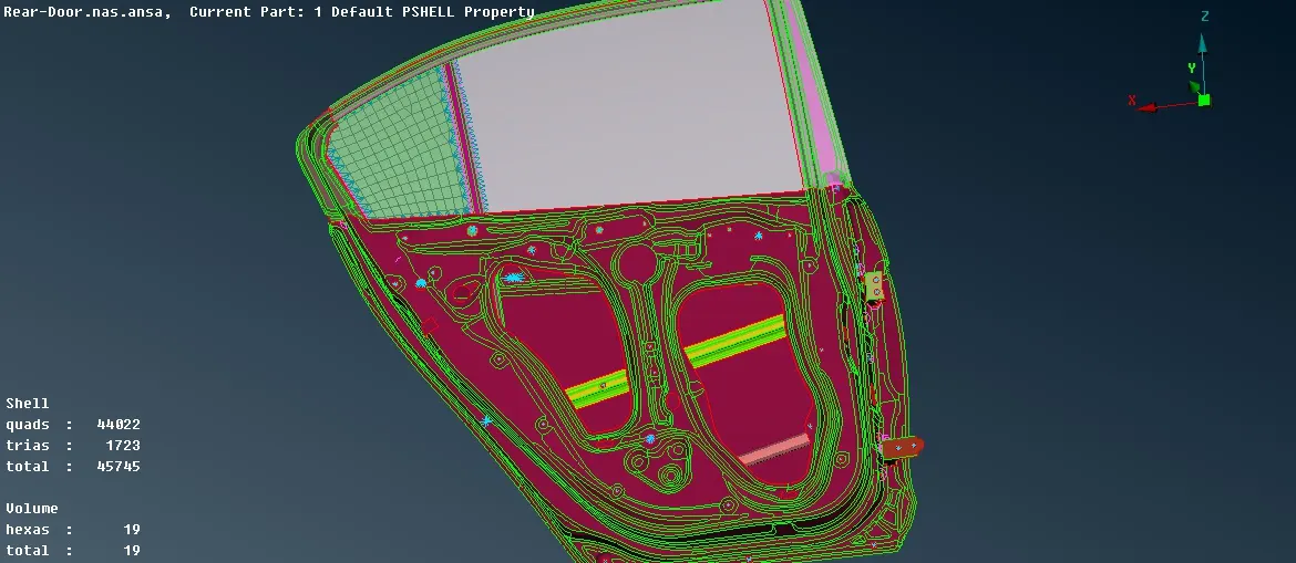
successfully identified and created different types of connections on the Rear door FE model using various elements.