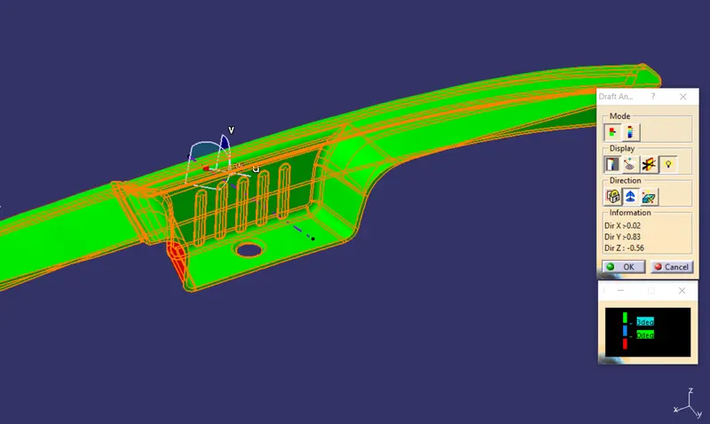
Door Arm Rest Week 8 Challenge
- AIM/OBJECTIVE: The creation of door arm rest and adding thickness to it.
- DETAILED REPORT:
- Terms utilized:
- Class A surface: It is the vehicle's external surface that provides it an appealing appearance. It can be physically touched. Reverse engineering is used to extract it from clay modeling. This surface is provided to the plastic product designer as input. Computer-aided industrial design programs are used to create Class-A surfaces.
- Class B surface: The offset from class A surface is used to produce the class B surface. All engineering features such as screw Bosses, Dog house, ribs, and mountings are produced on this surface.
- Class C surface: The surface that connects class A and class B is known as Class C surface.
- Tooling Axis: It is the direction in which core and cavity opens and closes.
- Slider direction: The mold release direction of a particular part may not be compatible with the mold opening direction of the Injection molding machine (product undercut) due to special design specifications. The slider, also known as slide, is a mold mechanism that was developed to tackle the undercut issue. The primary objective is to convert vertical mold opening and closing movement into horizontal movement. Different structural forms have been created to deal with the scenario when the undercut is placed in the core or cavity.
- METHOD FOLLOWED:
- Checking continuity of class-A surface.
- Deciding an appropriate tooling direction and creating a tooling axis.
- Performing draft analysis on class-A surface.
- Creating the class-B surface from the given class-A surface.
- Creating the class-C surface to join class-A and B surfaces.
- Creating the solid body by using the closed surface feature.
- Performing the draft analysis on the final Plastic component.
1) Checking continuity of class A surface:
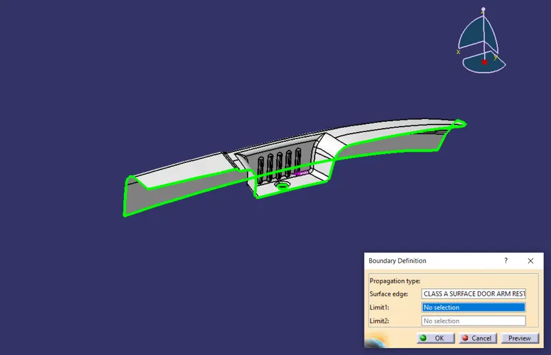
We must check the continuity of a given class-A surface to guarantee that it is properly joined or does not include any discontinuities.We can do this by using join or boundary commands.We can see that the surface has a continuously linked boundary, which is shown by the green line.
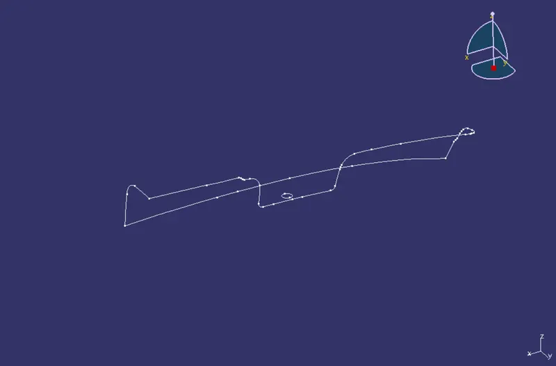
We can also check this by extracting boundry as shown in below image
2) Creating tooling axis direction:
The direction in which the core and cavity open or close are referred to as the tooling axis. Each and every section/face of a component is given a tiny draft angle in order for the component to be easily removed from the tool. Based on the draft conditions applied, the draft analysis technique is used to determine whether our CAD part model is manufacturable or not. The basic prerequisite for draft analysis is the determination of the tooling axis. Here we specify the direction in which the component should eject in order to facilitate tool removal. In a simple model, One tooling axis is sufficient to clear all the faces. But for complex models, we must provide a side core. In this type of model, to clear the entire component, more than one tooling direction is required. To begin, we must first create a main tooling axis for clearing all surfaces other than the side core surface or pocket.
- Creating main Tooling axis and slider direction.
- To begin, extract the basic surface and create a point on it. Insert the Axis system at that point. Take the intersection of the class A surface with the axis system's XZ plane. Along the vertical faces, draw point-point lines. Make a bisecting line with the two previous lines and a point.
- A tooling axis is a bisecting line. Using this tooling axis, conduct a draft analysis. We notice that a few component's faces are not green. So, with the exception of the pocket surface, tilt the compass to obtain a green tint on the entire top and back surface. The compass is then locked in place.
- Create the line by using a compass to determine the direction and passing through a point on the base surface. This is our main tooling axis. After that, unlock and reset the compass.
- Similarly, repeat the method to create a slider direction. Create a point on the vertical rib face by extracting it. Draw a line from the point to the surface's normal. By aligning the compass to the line, we can perform a draft analysis. Make all of the pockets surface green. The compass direction must be locked. Change the direction of the line. As a result, we have a Slider direction.
3) Performing draft analysis on class A surface:
- To perform draft analysis. Go to insert > Analysis > Feature draft analysis.
- Switch custom view parameter to material
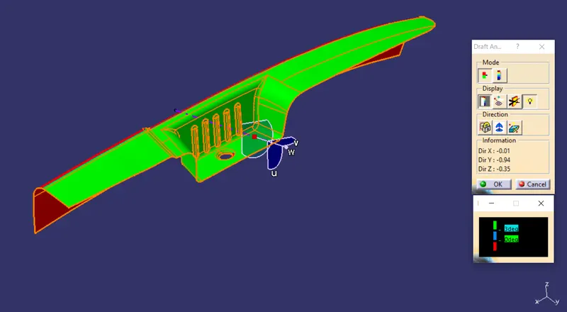
- Bring the compass close to the class-A surface by clicking on the compass icon. Align the compass with the tooling axis. We receive our results by clicking anywhere on the surface
- As can be seen in the image below, the surface in green has a 3-degree draft, which is essential for tooling practicality. Also, take a look at the color variants display box.
- Draft Analysis using main tooling axis.
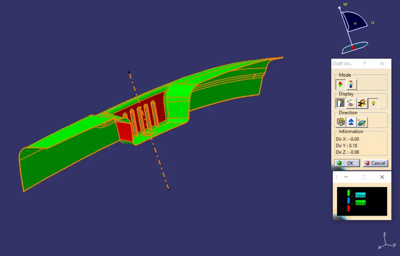
- Draft analysis using slider direction.
4) Creating class-B surface from given class-A surface.
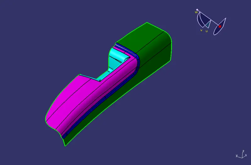
As indicated in the image below, divide class A surface into first half, second half, connecting fillet surface, and pocket surface. To get a class-B surface, work on each surface separately.
- First half: Surface marked in pink color.
- Second half: Surface marked in green color.
- Connecting fillet surface: Surface marked in blue color.
- Pocket surface: Surface marked in cyan color.
Follow the same procedure for all surfaces except for connecting fillet surface.
- Extract the class-A surface
- Untrim the surface
- Extrapolate untrimmed surface
- Offset it by 2.5 mm distance
- Trim unwanted extra surface
- Applying fillet as per formula to obtain uniform wall thicknes
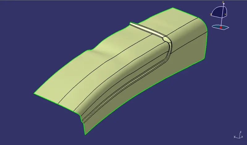
By following procedure class B surface is created as follows:
5) Creating class-C surface to join Class A and B surfaces.
- To obtain a class-C surface follow the below methodology. The entire class C surface is created in steps.
- First sweep extracted curve at 90 degrees to reference surface. This is a part of the class C surface.
- Sweep curve in draft direction and create surfaces as shown. Three patches of class C surface are created.
- Extrapolate swept surfaces then split them by line and form multi-section surfaces.
- Followed same methodology and all remaining class C surfaces are created.
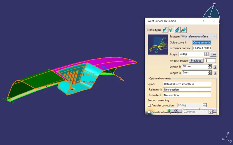
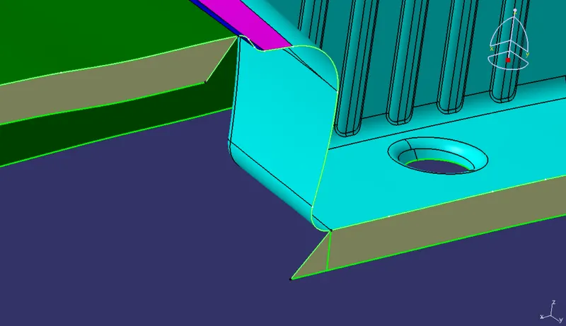
By following procedure class C surface is created as follows:
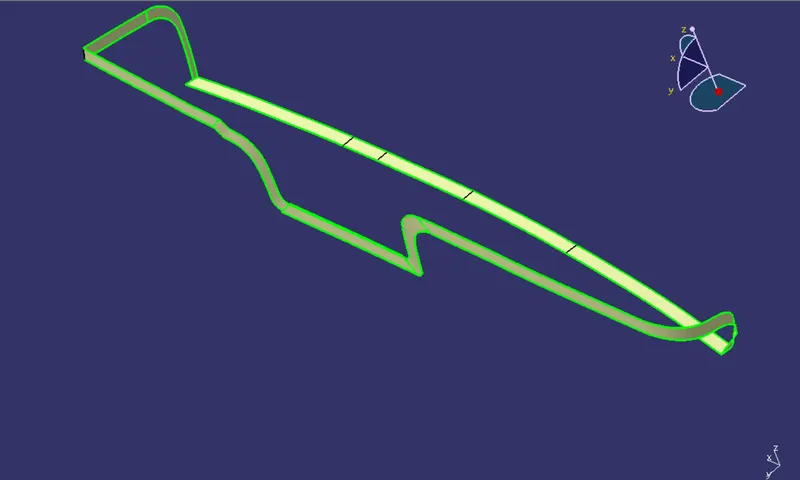
- Join classes A and C together.
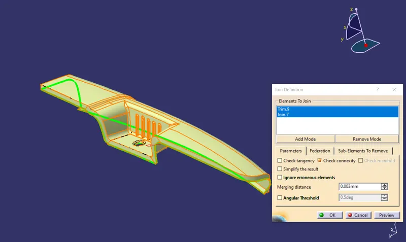
- Trim this join with class B surface to get a closed component.
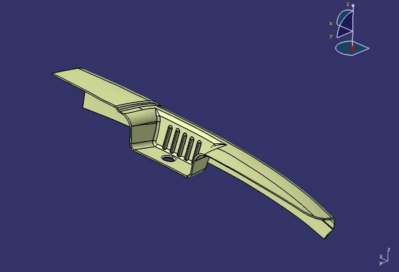
6) Creating solid model by using closed body feature:
- A solid model is created from a closed surface in the part workbench by using the closed surface command.

7) Performing draft analysis on a final plastic model.
- Performing draft analysis again with the same procedure as mentioned above for class-A surface.
- Draft analysis using main tooling axis.
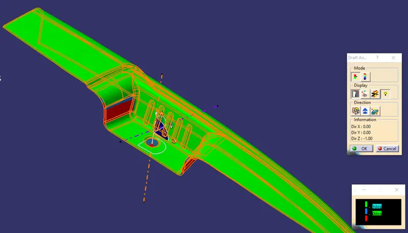
- Draft analysis using slider direction.