Door Arm Rest Week 8 Challenge
Title- Door Arm Rest Week 8 Challenge
Objectives-
1. To understand how to generate class B & class C surfaces from input class A surface
2. To understands importance of Tooling Axis
3. Create solid body using closed surfaces to create Door Armrest Solid Part.
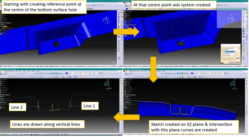
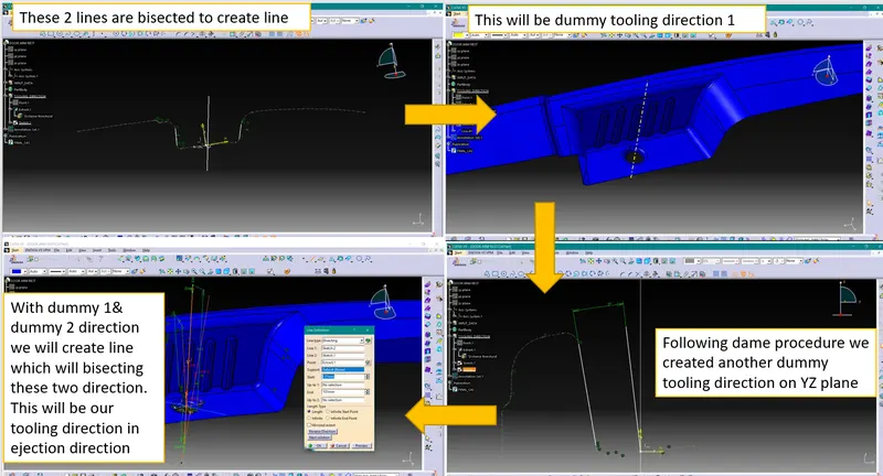
Creation of Tooling Axis by Bisecting method-
- We have performed draft analysis with the obtained tooling direction as shown below image
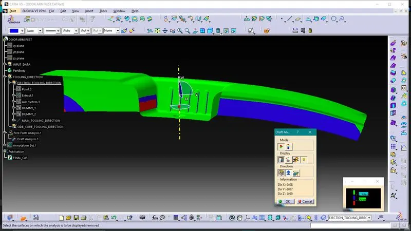
But as part surface is not even or it is having undercuts it will not get cleared in tooling direction we have created-
To manufacture this part there can be many solutions. Among these following 2 solutions are discussed-
1. Side Core-
We can adjust tooling axis in such a way that it will clear top & side faces of the part. And pocket type surfaces highlighted in red can be cleared using side core.
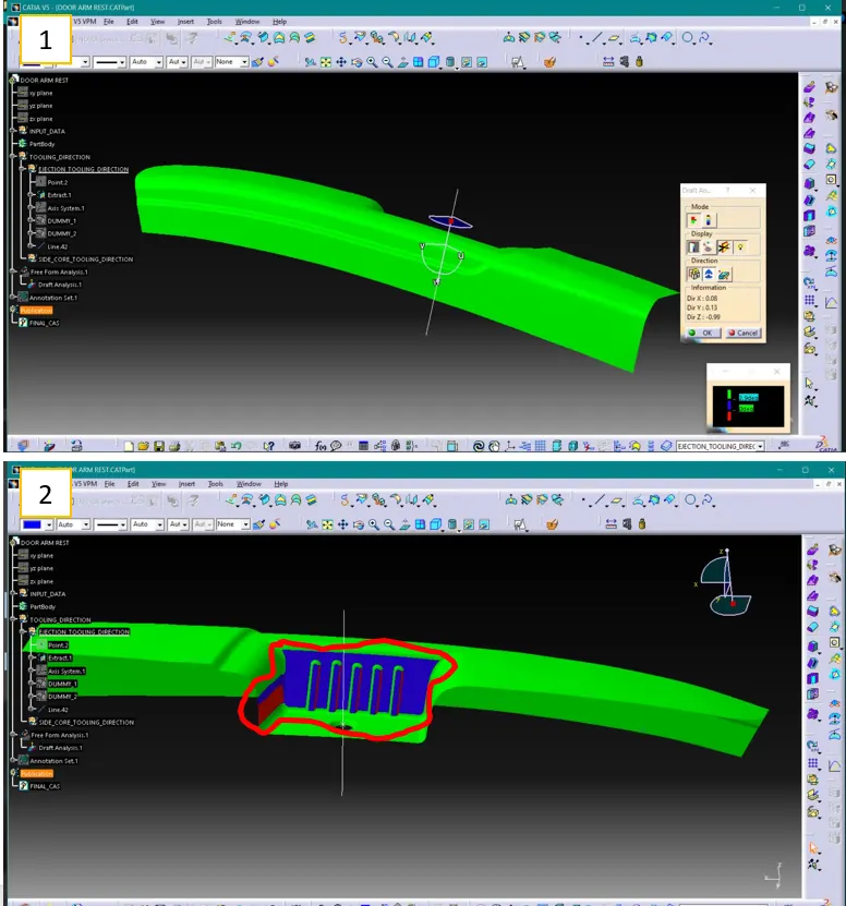
2. Lifter-
With help of lifter and using same tooling direction we can produce this part.
- From both the methods use of lifter will be more economical. So, to create thus component we will be using lifter method.
Creation of close surface using Class A, B & C surfaces-
a. Repairing CAS (Class A surface)
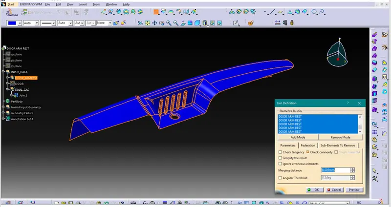
Input CAS from the styling team sometimes will have errors like gaps, unwanted surfaces, etc. To work on such input data will create problems. So, designer should observe the input surface & repair that input surface.
Finally, we should join all the surfaces & make it as single surface.
b. Creating Class B surface
Class B surface will be holding all engineering features like ribs, screw bosses, etc.
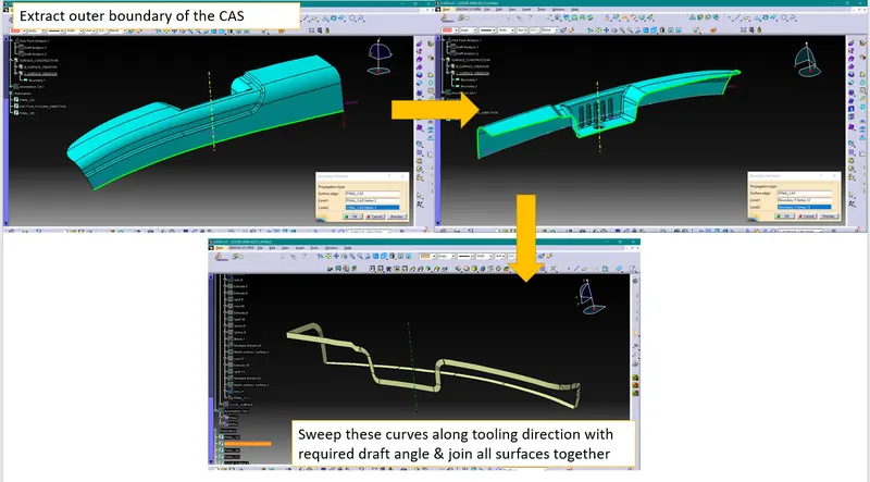
We need to create CBS (Class B surface) using CAS (Class A surface). The process of generating CBS is explained below-
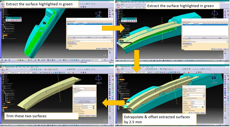
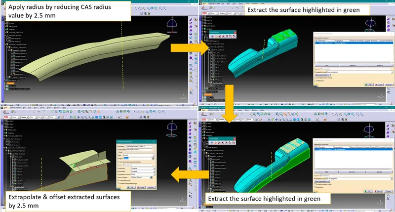
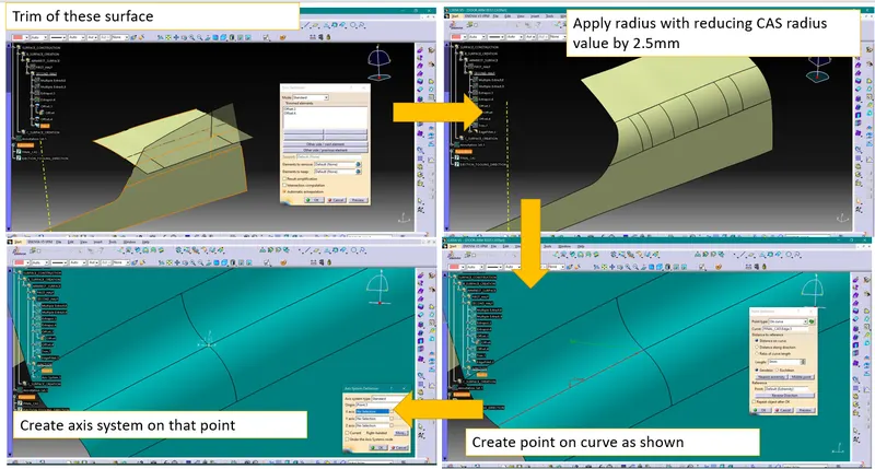
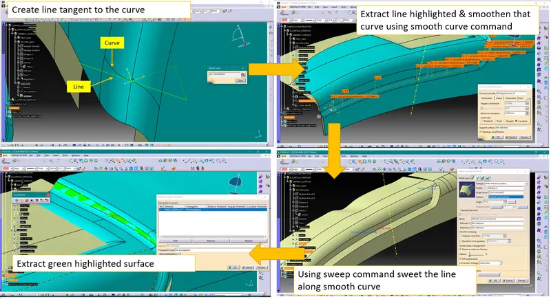
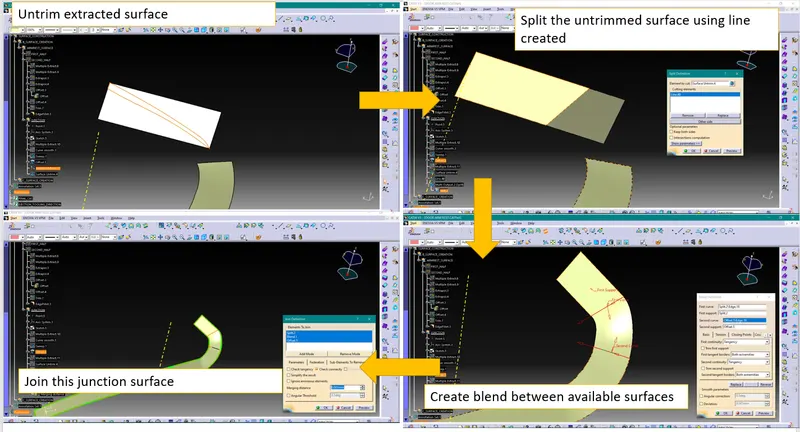
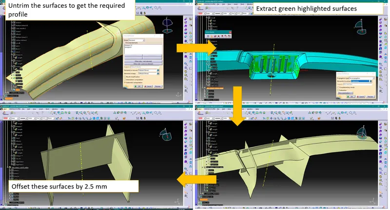
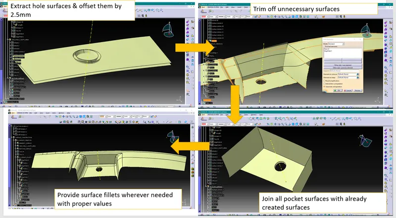
This process will produce required CAB (Class B surface).
c. Creating Class B surface
Draft Analysis-
Process of performing draft analysis in Catia V5-
1. Click on the draft analysis icon ( ) or go to Insert>Analysis>Feature Draft Analysis
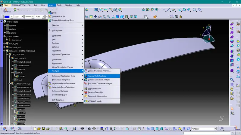
Note- While doing Draft analysis make sure you are enabling material view mode.
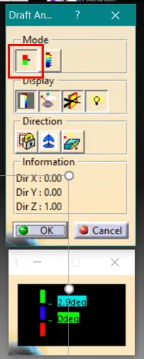
2. Switch on quick analysis mode by clicking on below highlighted icon
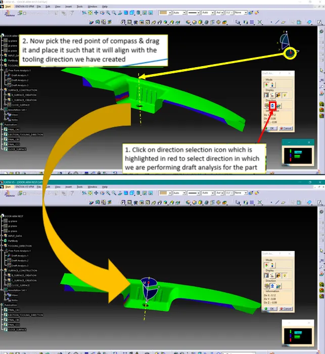
3. Selecting Draft Direction
4. Selecting surface
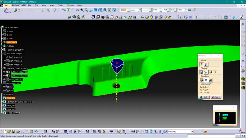
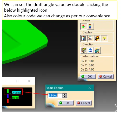
5. Input the draft angles
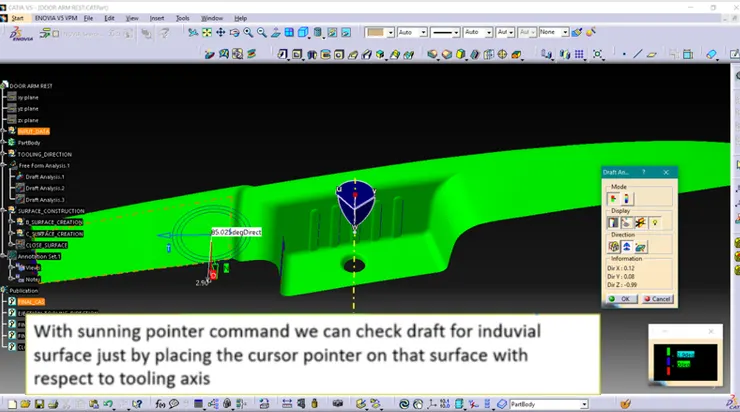
6. Running point
Draft analysis for CAS-
Draft analysis for Solid part-
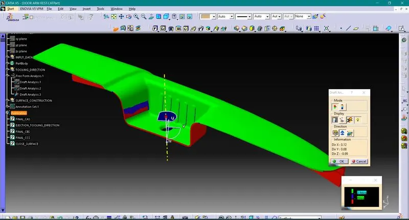
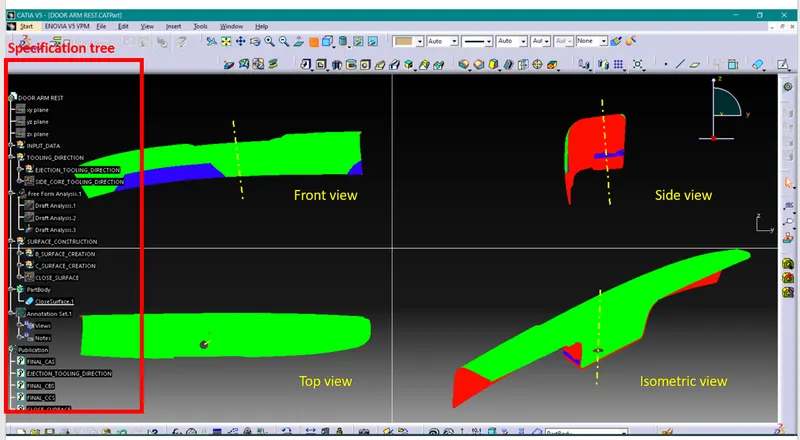
Solid model with the proper color code of the draft angle in various orientations (Isometric, Front, Side, and Top View)-
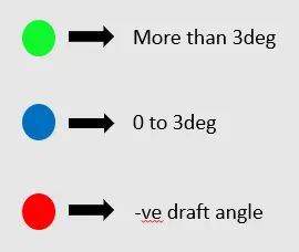
Screenshots of the solid model with the proper color code of the draft angle in various orientations-
Conclusion-
1. We have understood how to generate class B & class C surfaces from input class A surface
2. We have understood importance of Tooling Axis
3. We have understood importance of Draft & Draft analysis
4. We have created solid body using closed surfaces.