DEVALOPMENTOF A DOOR TRIM PANEL
Development of a Door Trim panel :
AIM: To Design a Door Trim Panel of an Automotive using CATIA v5
INPUTS :
- CLASS A surfaces of the DOOR ARM REST, MAP POCKET, BOTTLE HOLDER and LOWER SUBSTRATE.
- Master section for the attachment features.
OBJECTIVES :
- Analysing of given CLASS A surface and five neccesary modifications if any.
- Creating the tooling axis for all components.
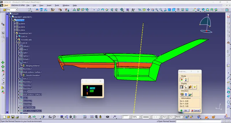
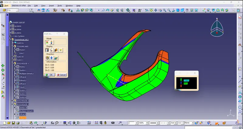
- Performing draft analysis on CLASS A surface.
- Creating CLASS B surface with respect to the CLASS A surface by using off set command.
- Creating of CLASS C surface by giving necessary DRAFT angles.
- Joining of CLASS C surface with CLASS A surface to make it as CLASS AC surface.
- Trim the CLASS ABC surfaces to make it as a body.
- Creating closed body for all the components.
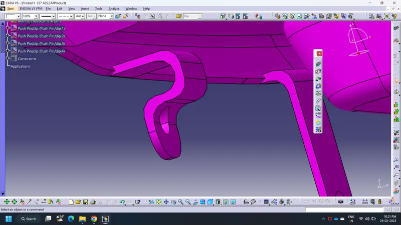
- Creating the attachments on the LOWER SUBSTRATE for assembly like DOG HOUSE, HEAT STAKES, AND RIBS.
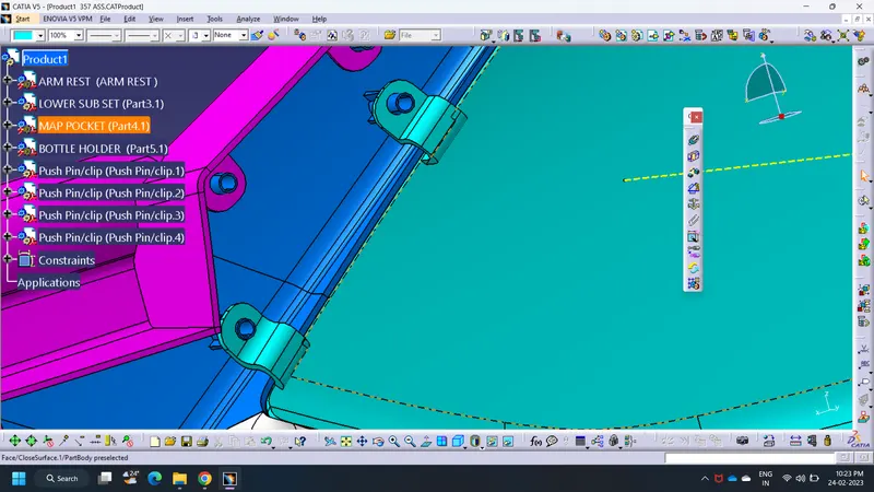
- Creating the flanges on the other three components for the assembly purpose.
- Creating the Side core tooling axis.
- Performing the vigrous draft analysis and make sure all parts are clearing with positive and required draft.
CLASS A SURFACES:
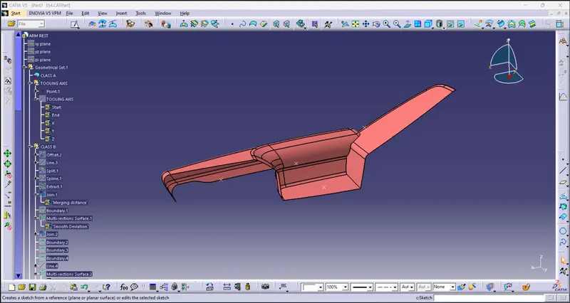
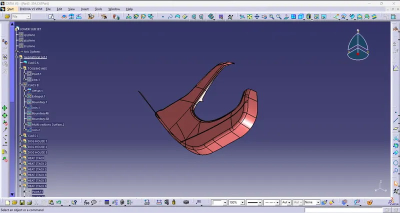
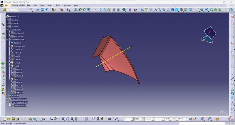
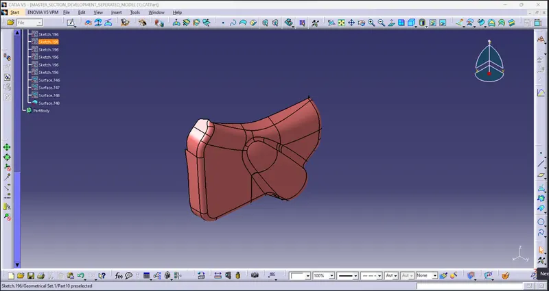
Class A surface refers to those surfaces which are VISIBLE and abide by the physical meaning, of a product. This classification is primarily used in the automotive and increasingly in consumer goodsIt is a requirement where aesthetics has a significant contribution.
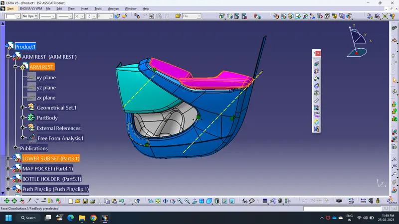
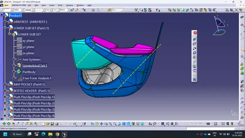
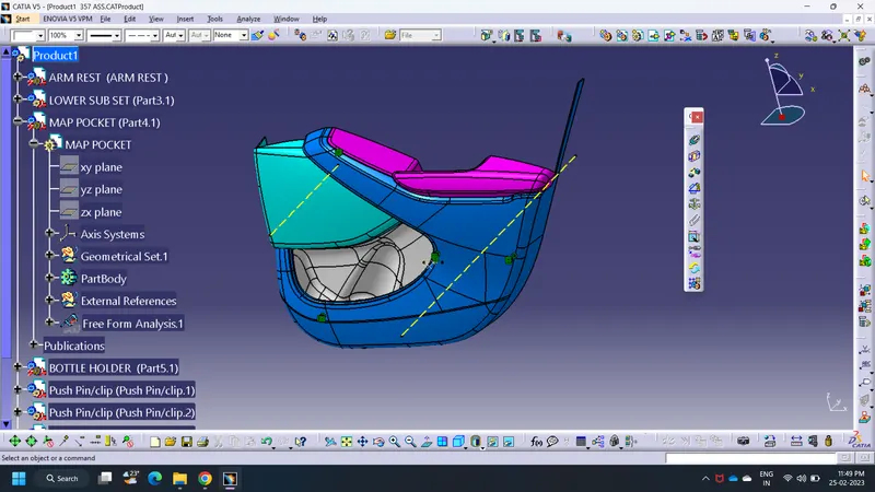
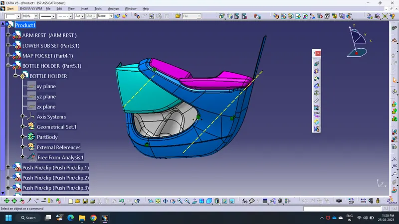
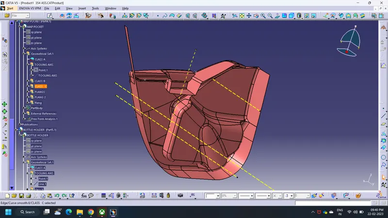
Below mentioned images are the CLASS A surfaces of the respevtive components.
A) ARM REST:
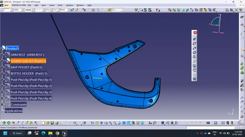
B) LOWER SUBSTRATE:
C) MAP POCKET:
D) BOTTLE HOLDER:
OVERALL SURFACES IN ASSEMBLY WORKBENCH:
DRAFT ANALYSIS ON CLASS A SURFACES:
A) ARM REST:
B) LOWER SUBSTRATE:
C) MAP POCKET:
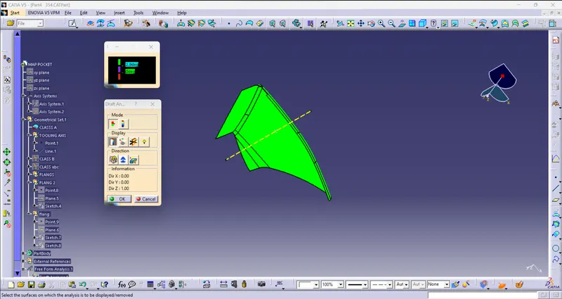
D) BOTTLE HOLDER:
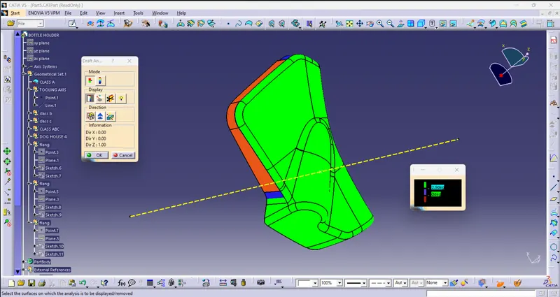
CREATION OF TOOLING AXIS:
- Tooling axis plays important role in plastic product manufacturing and designing, this axis decides the direction in which mould is going to work while production of the component.
- The main focus while deciding the tooling axis is clearing the component in the moulding in the same axis with the minimum use of the side core for producing the component, the side core usually adds up to the cost of the component.
- For the particular component X,Y and Z can be the possible direction for the tooling axis.
- You must specify the axis system by creating the point on the surface.
- With the help of the intersect in the YZ plane create the tooling axis in YZ plane .
- With the help of the intersect in the ZX plane create the tooling axis in ZX plane.
- The last step is to bisect the two tooling axis to obtain the main tooling axis of the class A surface.
A) ARM REST:
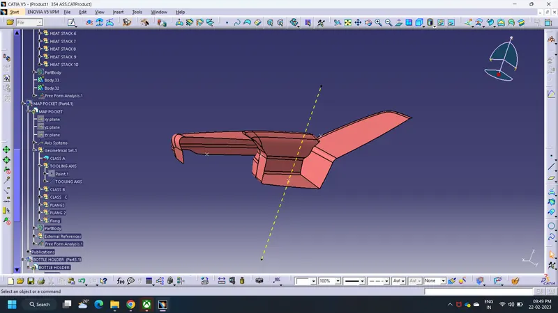
B) LOWER SUBSTRATE:
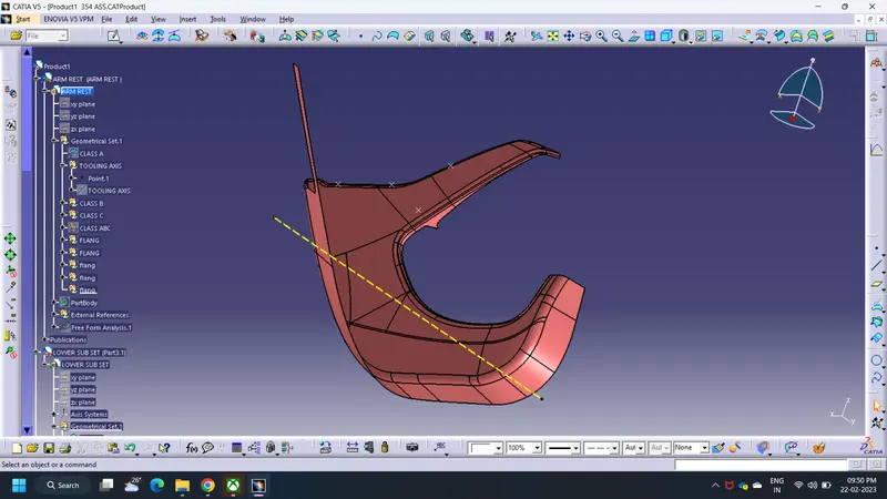
C) MAP POCKET:
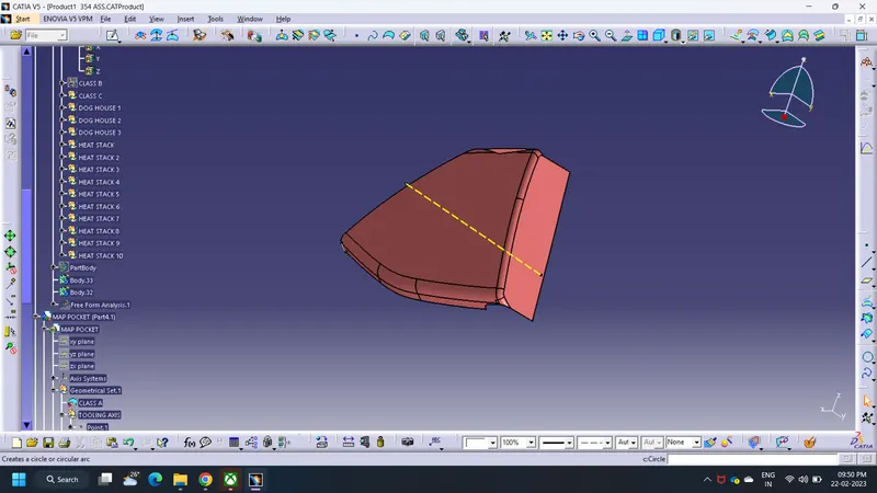
D) BOTTLE HOLDER:
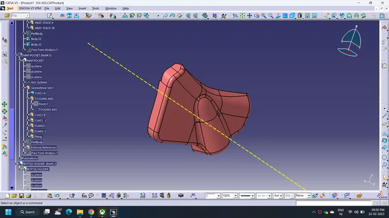
CLASS B SURFACES:
A Class B surface is something that is not always visible i.e. the underside of a fascia that you would have to bend down to see.
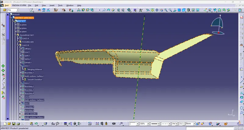
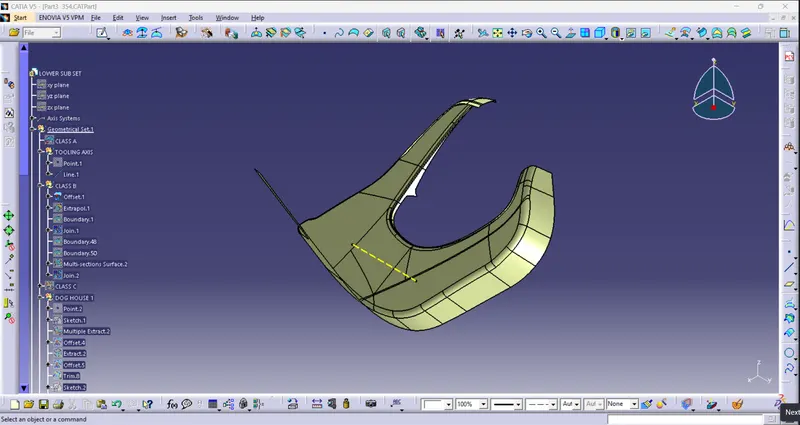
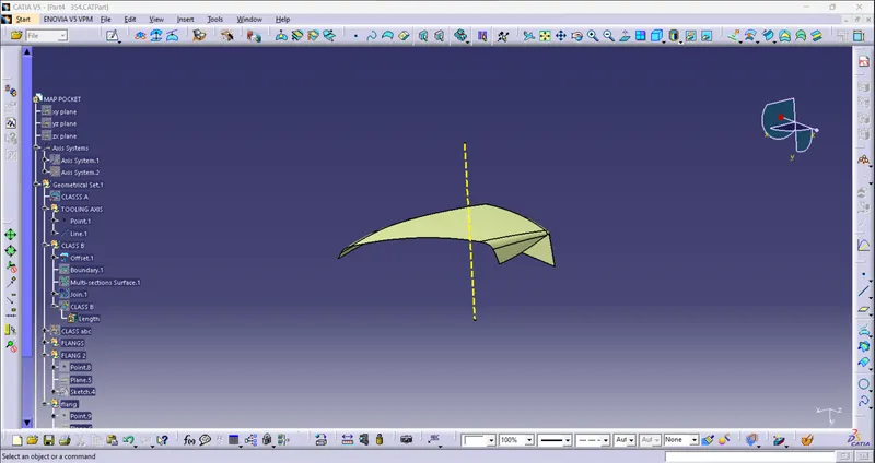
- The the class B surface is the surface where all the necessary attachments and supports of the component is made .
- The main parts without the edge fillets are extracted and untrimmed and then they are extrapolated for better view.
- The extrapolated parts are then made offset with reference to the class A with the thickness of the component, here thickness of the components is 2.5 mm.
- The offset surfaces are then extrapolated to attain the class B surface.
- You can even directly offset the class A for obtaining the class B surface.
- The final class B surface must have the edge fillets similar to the class A and fillets must be given properly with a thought of maintaining same thickness throughout avoiding the flow line defects.
A) ARM REST:
B) LOWER SUBSTRATE:
C) MAP POCKET:
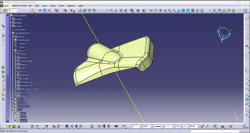
D) BOTTLE HOLDER:
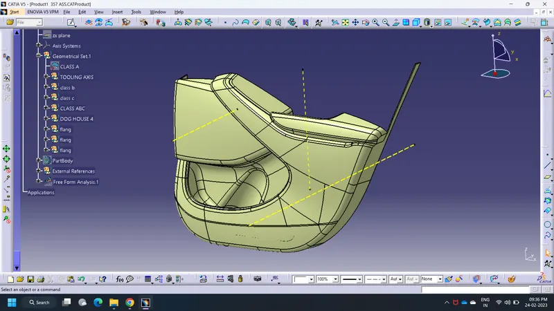
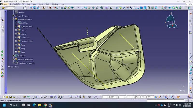
OVERALL SURFACES IN ASSEMBLY WORKBENCH:
CREATION OF CLASS C AND TRIM OF CLASS ABC:
A) ARM REST:
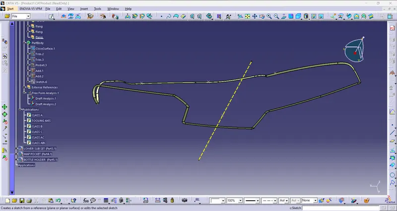
B) LOWER SUBSTRATE:
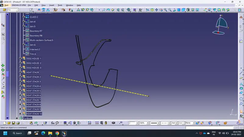
C) MAP POCKET:
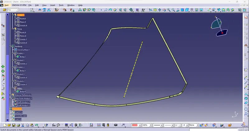
D) BOTTLE HOLDER:
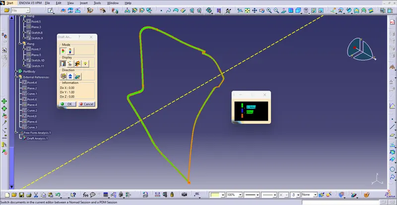
CREATING THE CLOSED BODY AND ASSIGNING IT AS MAIN BODY:
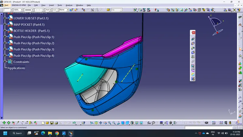
- Move to the part window and with the help of surface based feature close the surface to get the closed part body.
- Follow this for all the components.
CREATING THE ATTACHMENT FEATURES FOLLOWING THE MASTER SECTION:
#HEAT STAKES
- Heat Staking is a pulsed-heat process to join two or more parts out of which one at least is made of plastic.
- The process is to deform the plastic material using heat and force at a set process time.
- The bond is made by partially de-forming the plastic part in order to fix the other.
- Heat Staking makes it easy to bond metal to plastic and is commonly used in high volume/low cost applications such as automotive, IT and consumer appliances.
- Similar and dissimilar materials may be joined: metal to metal, plastic to plastic, metal to plastic
- Accurate control operating within a small process window
- Local heating resulting in no damage to surrounding materials
- Processing of glass-filled materials
- No mechanical vibration
- Many heat-stake shapes possible through custom designed tools.
#RIBS
- The ribs provide economical stiffness and strength to the part without increasing the overall thickness of the part.
- The ribs are used as locating and arresting in the assembly as locators.
- Proper allignment in mating parts, slot and rib pair is long lasting other than screw pair which loosen up with time.
- Acting as stops or guide for mating the tilted headlamps.
- Rib designs includes.
- Thickness, quantity, height , manufacturibility and location.
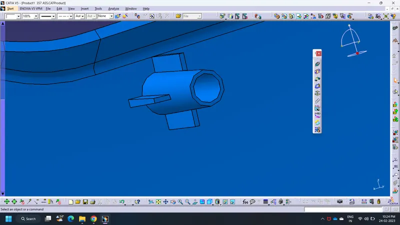
#HEAT STAKE:
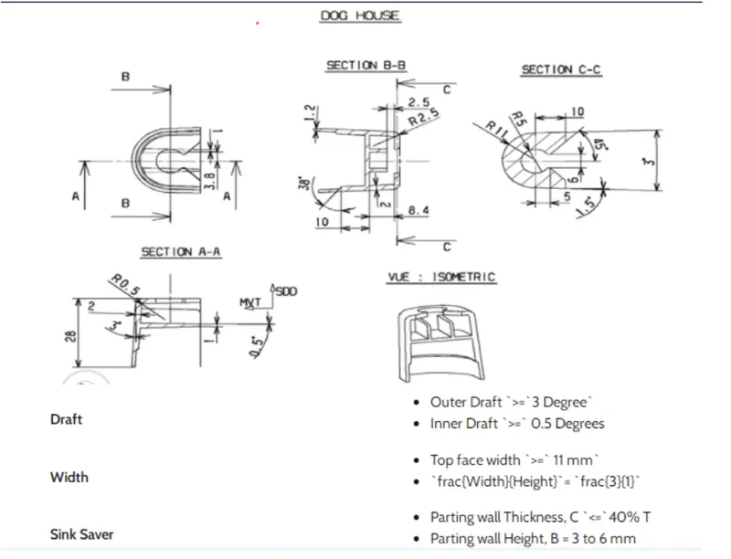
#DOG HOUSE:
DIMENSIONS OF DOG HOUSE:
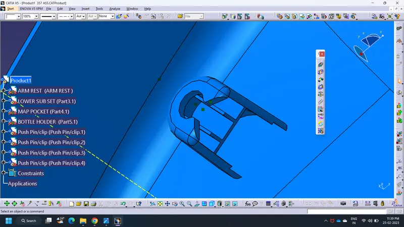
DOG HOUSE AFTER MODELING:
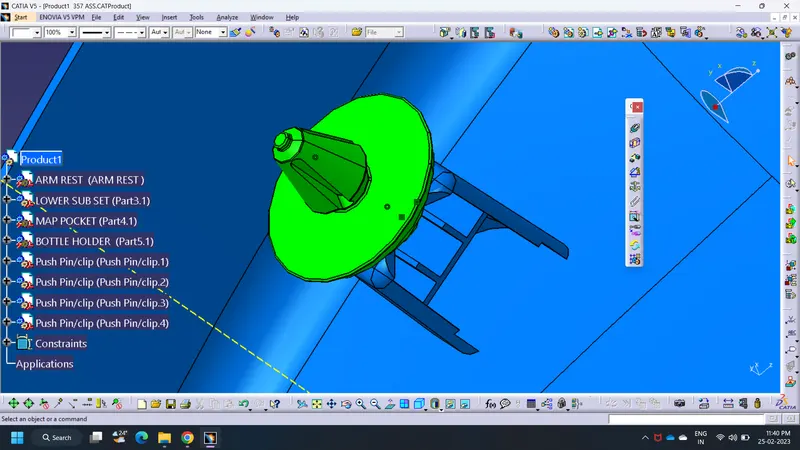
#DOG HOUSE WITH PUSHPIN CLIP:
#LOWE SUBSTRATE HAVING ALL ATTACHMENT FEATURES:
FLANGES ON THE COMPONENT:
- These flanges will be build on the components for the fittment purpose with lower substrate.
- The hole at center will be guided along the heat stakes.
- Later top portion of the heat stake will be melted over it.
- The flange should rest on the supporting ribs on side.
FLANGES ON ARM REST:
FLANGES ON MAP POCKET:
FLANGES ON BOTTLE HOLDER:
DRAFT ANALYSIS OF THE COMPONENTS:
DRAFT ANALYSIS ON ARM REST:

DRAFT ANALYSIS ON LOWER SUBSTRATE:

DRAFT ANALYSIS ON MAP POCKET:
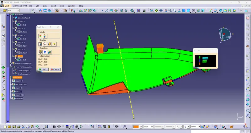
DRAFT ANALYSIS ON BOTTLE HOLDER:
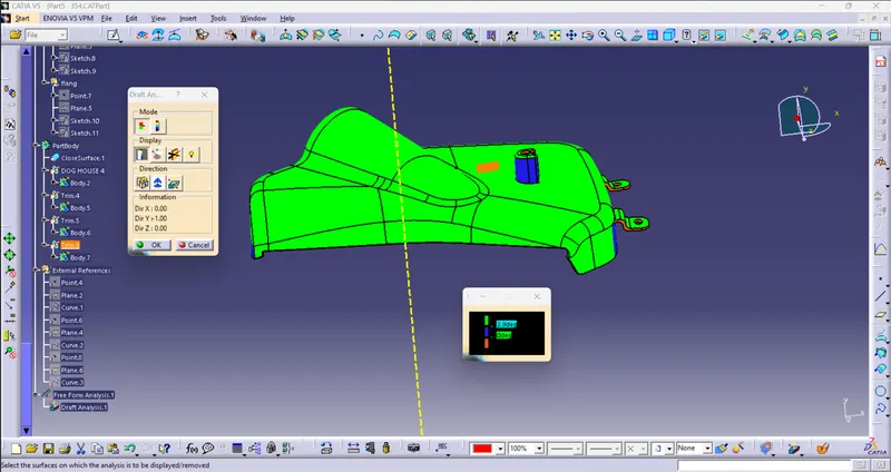
DRAFT ANALYSIS ON DOG HOUSE HAVING SIDE CORE AXIS:
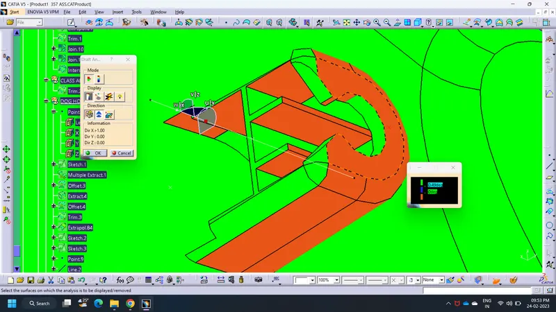
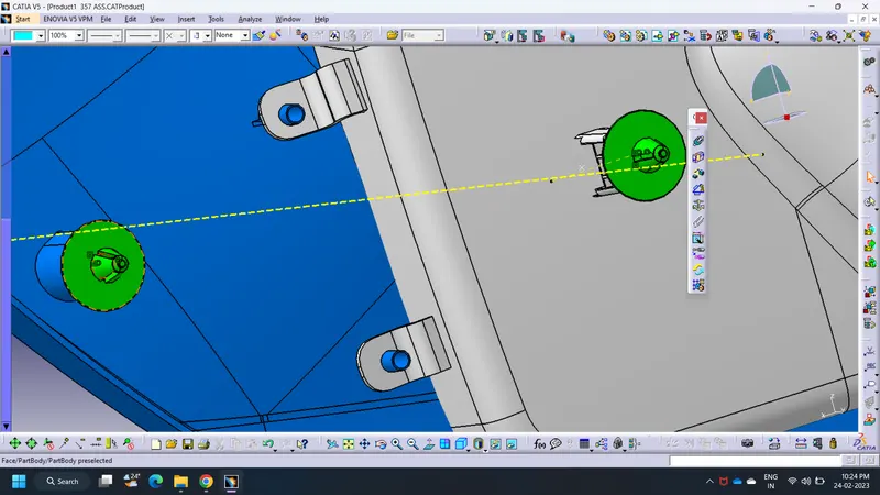
ASSEMBLY CONSTRAINTS FOR PUSHPIN CLIPS:
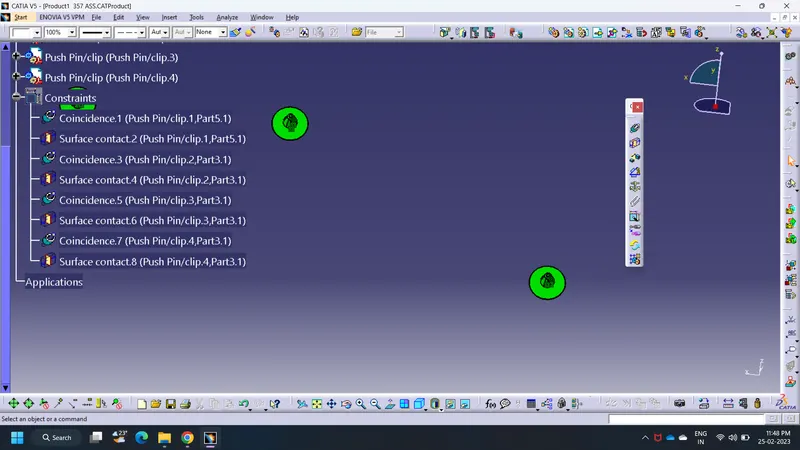
TREE STUCTURE: