Designing of Cam profile
Aim- Design a cam profile path to convert rotary motion into reciprocating motion.
challenge task- make a program that can required a inputs as a angle of ascent, descent and dwell angle so it can run after passing inputs angle.
Objective- objective of this poject is that design a cam profile that is more pricise so it can used in automobile applications such as in IC engine to operate a inlet and exhaust valve.
Motivation- Recently i have visited a garage to servicing of my bike where a mechanic adjust a time valve for less fuel consumption a remember the concept of adjusting such valves are actually work by using cam and follower. so i thought this path can be drawn using a softwares like auto cad or matlab, so i decided to work on it.
Methodology- In this project we are going to design a cam profile for any specefic application. We consider the input parameters as per the defined applications such as for a inlet and exhaust valves operating in a IC engine by providing the input parametes such dwell angle, ascent and descent angle. On the basis of the input, we are going to design the cam profile and its displacement curve.
Application -
Module- Matlab R2021a and GNU octave.
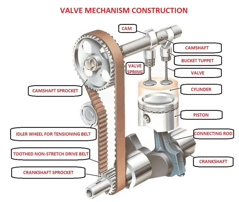
Basic concepts for design of cam and follower- A cam is a rotating machine element which gives reciprocating or oscillating motion to another element called follower. The cams are usually rotated at uniform speed by a shaft and these cams converts its rotary motion into linear or reciprocating motion using follower.
Basic Theory
A. CAM- a cam is rotating or sliding member in a mechanical linkage forming a higher pair mainly it transfer ratarry motion to linear motion
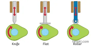
Necessary elements of a cam mechanism-
1. A driver member - the cam
2. A driven member - the follower
3. A frame which supports the frame and guides the follower.
Types of Cams- Cams are classified according to:
1. Shape
2. Follower movement
3. Manner of constraint of the follower
1. According to Shape
a) Wedge and flat cams b) Radial or disc cams c) Spiral Cams d) Cylindrical Cams e) Conjugate
Cams f) Globoidal Cams g) Spherical Cams
2. According to follower movement
a) Rise Return Rise (R-R-R) b) Dwell Rise Return Dwell (D-R-R-D) c)Dwell Rise Dwell Return Dwell (D-R-D-R-D)
3. According to Manner of Constraint of the Follower
a) Pre loaded Spring Cam b) Positive drive Cam C) Gravity Cam
Cam Terminolgy- Before designing cam profile it is necessary to understand the cam terminology to provides an inputs in coding
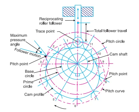
1.Base Circle- It is the smallest circle tangent to the cam profile drawn from the centre of rotation of a radial cam. 2.Trace Point- It is a reference point on the follower to trace the cam profile such as the knife edge of a knife edged follower and centre of the roller of a roller follower.
3. Pitch curve- It is the curve drawn by the trace point assuming that the cam is fixed, and the trace point of the follower rotates
around the cam.
4. Prime circle- The smallest circle drawn tangent to the pitch curve is known as the prime circle.
5. Pressure angle- The pressure angle, representing the steepness of the cam profile, is the angle between the normal to the pitch curve at a point and the direction of the follower motion.
6. Pitch point- It is the point on the pitch curve at which the pressure angle is maximum.
7. Pitch circle- It is the circle passing through the pitch point and concentric with the base circle.
8. Lift or stroke- It is the maximum travel of the follower from its lowest position to the topmost position.
9. Angle of ascent- It is the angle through which the cam turns during the time the follower rises.
10. Angle of dwell- It is the angle through which the cam turns while the follower remains stationary at the highest or lowest position.
11. Angle of descent : It is the angle through which the cam turns during the time the follower returns to the initial position.
B. FOLLOWER
The follower is a reciprocating element of a machine that follows the movement of the cam by direct contact. When a cam travels in rotary movement, the follower moves linear wrt axis.
Types of motions of followers
1. Simple Harmonic motion- SHM is defined as a motion in which the restoring force is directly proportional to the displacement of the body
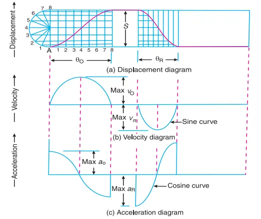
displacement of follower during ascent
`h/2(1-cos(pitheta)/(phiascent))`
where,
theta is rotation of cam angle
phi is the angle of ascent , descent depend on condition
Displacement of follower during descent
`h- h/2(1-cos((pitheta)/(phidescent))`
lets simplify this for matlab-
Lift During Ascent:
h_ascent = (0.5*h).*(1-cosd((180/ascent).*theta(theta<ascent)))
Lift During Descent:
h_descent = h-((0.5*h).*(1 - cosd((180/descent).*theta(theta<=descent))))
2. Uniform Velocity Motion- The condition in which a body covers equal distance in an equal interval of the time is known to be uniform velocity
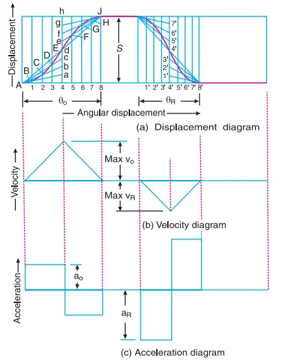
Displacement of follower during ascent
`(htheta)/(phiascent)`
Displacement of follower during descent
`h-((htheta)/(phidescent))`
simplify for matlab,
Lift During Ascent:
h_ascent = (h/ascent).*theta(theta<ascent);
Lift During Descent:
h_descent = h- (h/descent).*theta(theta<=descent);
3. Cycloidal Motion- cycloid is the curve traced by a point on a circle as it rolls along a straight line without slipping. cycloidal method is more accurate than any other methods.
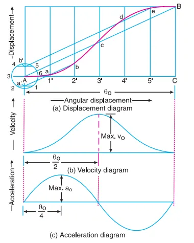
Displacement of follower during ascent
`h/pi[(pitheta)/(phiascent)-1/2sin(2pitheta)/(phiascent)]`
Displacement of follower during descent
`s = h/pi[(pitheta)/(phidescent)-1/2sin(2pitheta)/(phidescent)]`
Simplify for matlab
h_ascent = (h/pi)*(((pi/ascent).*theta(theta<ascent)) - 0.5*sind((2*180/ascent).*theta(theta<ascent)))
h_descent = h - ((h/pi)*(((pi/descent).*theta(theta<=descent)) - 0.5*sind((2*180/descent).*theta(theta<=descent))))
General considerations-
- Maximum cam angle is 360 degree
- maximum lift of follower is 50 mm
- Ascent angle should be 60 degree
- descent angle should be 90 degree
- Dwell angle should be 45 degree
Condition- Codes should take any values as inputs in specific limits like angle between 0 to 360 and lift 0 to 100
Codes structure
- clearing commands and workspace
- codes for passing inputs during run
- selection of motions
- conditions for ascent and descents
- plotting cam angles and lift of followers
- defining radius of followers and joint them
- plotting cam profile using polar plotting
- converting polar plot into cartesion co ordinates
Main Matlab Program
% Final Independant Project
% Title : Design of Cam with its profile generated in MATLAB
%Lets clear command window before running program

clear all
close all
clc

%Lift and Base Circle Radius
h = input('Lift of Follower (mm) n');
r = input('Base Radius (mm) n');

%Ascent and Descent Angles
ascent = input('Ascent Angle n');
dwell_1 = input('Dwell Angle n');
descent =  input('Descent Angle n');
dwell_2 = 360-(ascent + dwell_1 + descent);

%Additional Angles for our convenience
after_ascent = ascent + dwell_1;
after_descent = after_ascent + descent;

%Cam Angle
theta = linspace(0,360,361);

%Let us consider SHM Motion, Uniform Velocity, Cycloidal
%Adding Motion Selector Window
motion_list = {'Simple Harmonic Motion','Uniform Velocity','Cycloidal'};
[ascent_motion] = listdlg('ListSize',[300,100],'Name','Select Ascent Motion','SelectionMode','single','ListString',motion_list);
[descent_motion] = listdlg('ListSize',[300,100],'Name','Select Descent Motion','SelectionMode','single','ListString',motion_list);

%Ascent Motion Conditions
if ascent_motion == 1 %SHM
    h_ascent = (0.5*h).*(1-cosd((180/ascent).*theta(theta<ascent)));
elseif ascent_motion == 2 %Uniform Velocity
    h_ascent = (h/ascent).*theta(theta<ascent);
elseif ascent_motion == 3 %Cycloidal
    h_ascent = (h/pi)*(((pi/ascent).*theta(theta<ascent)) - 0.5*sind((2*180/ascent).*theta(theta<ascent)));
end

%Descent Motion Conditions
if descent_motion == 1 %Simple Harminic Motion
    h_descent = h-((0.5*h).*(1 - cosd((180/descent).*theta(theta<=descent))));
elseif descent_motion == 2 %Uniform Velocity
    h_descent = h- (h/descent).*theta(theta<=descent);
elseif descent_motion == 3 %Cycloidal Motion
    h_descent = h - ((h/pi)*(((pi/descent).*theta(theta<=descent)) - 0.5*sind((2*180/descent).*theta(theta<=descent))));
end

%Plotting Cam Angle Vs Lift
plot(theta(theta<ascent),h_ascent,theta(theta>=after_ascent & theta<=after_descent),h_descent);
set(gca,'XTick',(0:10:after_descent))
set(gca,'YTick',(0:5:h))
set(gcf,'position',[0,0,6000,400])
title('Cam Angle Vs Lift')
xlabel('Cam Angle (degrees)');
ylabel('Lift of follower (mm)');

h_dwell1 = ones(1,dwell_1).*h;
h_dwell2 = zeros(1,dwell_2);

%Defining radii during different phases of Cam
r1 = r + h_ascent;
r2 = r + h_dwell1;
r3 = r + h_descent;
r4 = r + h_dwell2;

%Joining all radii
r = [r1 r2 r3 r4];

%Convert theta to radians
theta_radians = deg2rad(theta);

%Plotting Cam Profile
figure
polarplot(theta_radians,r);
title('cam profile in polarplane')
set(gca,'ThetaZeroLocation','top')

%Converting Polar to Cartesian Coordinate System
[x,y] = pol2cart(theta_radians,r);
x_cord = transpose(x);
y_cord = transpose(y);
z_cord = zeros(360,1);
Snaps of Codes-
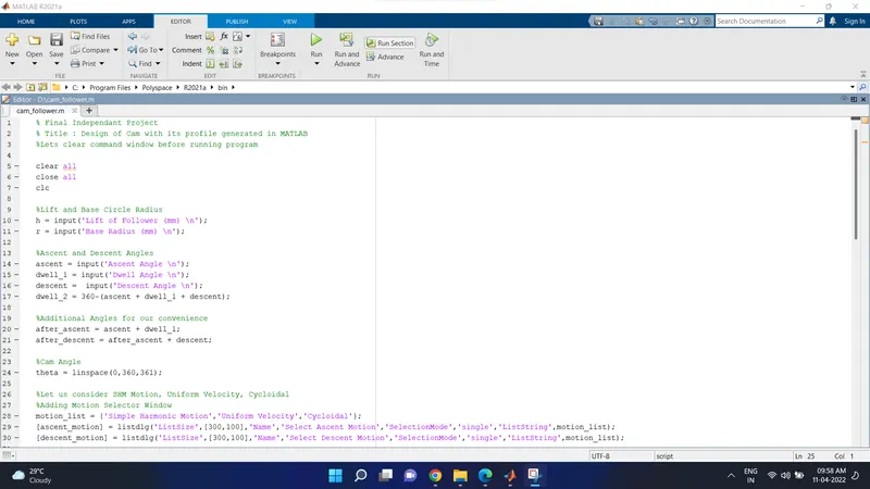
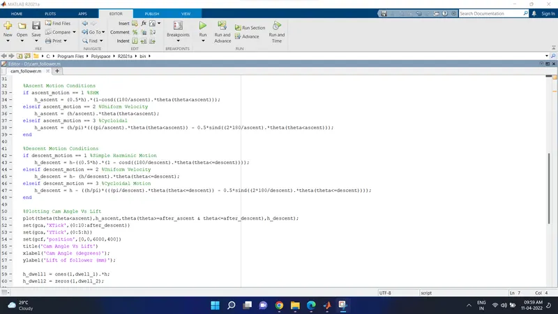
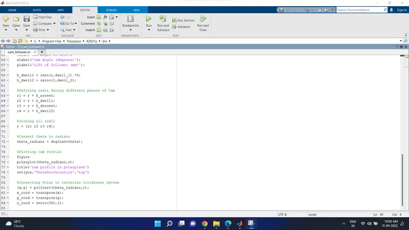
Explanaion of codes-
clear all - clearing all variable in current window
close all -for closing all figure windows
clc - for clearing command window
h = input('Lift of Follower (mm) n'); - to passing the height or lift of follower
r = input('Base Radius (mm) n'); - to passing the radius of cam
ascent = input('Ascent Angle n'); - to passing the ascent angle during run
dwell_1 = input('Dwell Angle n'); - to passing the dwell after ascent during run
descent = input('Descent Angle n'); - to passing the descent angle during run
dwell_2 = 360-(ascent + dwell_1 + descent); - remaining angle after all passing angle such that (360-sum of remaining angles)
after_ascent = ascent + dwell_1;
after_descent = after_ascent + descent; - additional angles for our convenience
theta = linspace(0,360,361); - generating cam angle by defining matrix, starting angle 0, maximimum angle 360 degree and 360 values stored in variable called theta
motion_list = {'Simple Harmonic Motion','Uniform Velocity','Cycloidal'}; - adding motion selection window between SHM Motion, Uniform Velocity, Cycloidal motion
[ascent_motion] = listdlg('ListSize',[300,100],'Name','Select Ascent Motion','SelectionMode','single','ListString',motion_list); - is used to create a dialog box for selection of motion during ascent f size 300 x 100
[descent_motion] = listdlg('ListSize',[300,100],'Name','Select Descent Motion','SelectionMode','single','ListString',motion_list); - is used to create a dialog box for selection of motion during descent of size 300 x 100
if ascent_motion == 1 %SHM
h_ascent = (0.5*h).*(1-cosd((180/ascent).*theta(theta<ascent))); putting conditions and formula for simple harmonic motion during ascent
elseif ascent_motion == 2 %Uniform Velocity
h_ascent = (h/ascent).*theta(theta<ascent); - putting conditions and formula for uniform velocity motion during ascent
elseif ascent_motion == 3 %Cycloidal
h_ascent = (h/pi)*(((pi/ascent).*theta(theta<ascent)) - 0.5*sind((2*180/ascent).*theta(theta<ascent))); - putting conditions and formula for cycloidal motion during ascent
end - to end the if loop
if descent_motion == 1 %SHM
h_descent = h-((0.5*h).*(1 - cosd((180/descent).*theta(theta<=descent)))); - putting conditions and formula for simple harmonic motion during descent
elseif descent_motion == 2 %Uniform Velocity
h_descent = h- (h/descent).*theta(theta<=descent); - putting conditions and formula for uniform velocity motion during descent
elseif descent_motion == 3 %Cycloidal
h_descent = h - ((h/pi)*(((pi/descent).*theta(theta<=descent)) - 0.5*sind((2*180/descent).*theta(theta<=descent)))); - putting conditions and formula for cycloidal motion during descent
end - to end the if loop
plot(theta(theta<ascent),h_ascent,theta(theta>=after_ascent & theta<=after_descent),h_descent); - plotting a curve of generated variabls using plot command
set(gca,'XTick',(0:10:after_descent)) - to return current x axis and give values to x axis 0 to 10
set(gca,'YTick',(0:5:h)) - to return current y axis and give values to y axis 0 to 5
title('Cam Angle Vs Lift')
xlabel('Cam Angle (degrees)');
ylabel('Lift of follower (mm)'); - to give title a name and labels
h_dwell1 = ones(1,dwell_1).*h;
h_dwell2 = zeros(1,dwell_2); - to provide a height of follower during dwell angle after ascent and descent
r1 = r + h_ascent;
r2 = r + h_dwell1;
r3 = r + h_descent;
r4 = r + h_dwell2; - defining the radius of cam during different phases
r = [r1 r2 r3 r4]; - joining all radius
theta_radians = deg2rad(theta); - conerting theta values into radians
figure - make figure window
polarplot(theta_radians,r); - plotting polar co-ordiates of theta in radians and radius of cam
set(gca,'ThetaZeroLocation','top') - return to current axis
[x,y] = pol2cart(theta_radians,r); - converting polar coordinates to cartesion coordinates system
x_cord = transpose(x); - convert x cordinates values into matrix using transpose command
y_cord = transpose(y); - convert y cordinates values into matrix using transpose command
z_cord = zeros(360,1); - This form of syntax returns an array containing all elements as zeros
Outputs
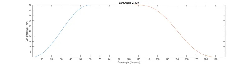
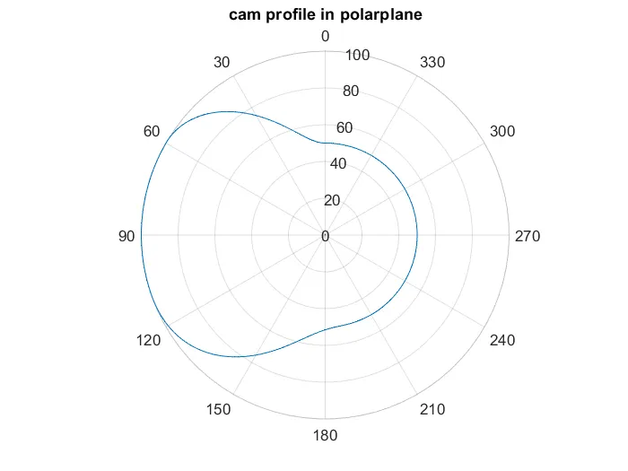
Validation -
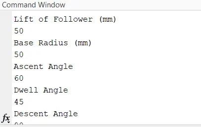
Matlab asking for inputs this our first validation
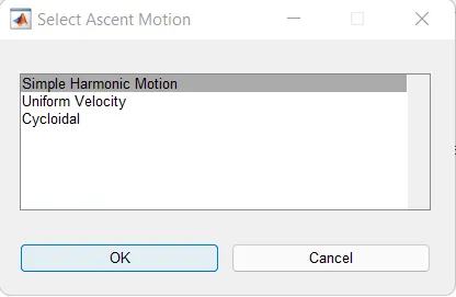
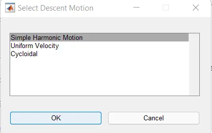
During run it ask for motion selection during ascent and descent this is our second validation.
Errors
- Most of the errors are typo errors
- use of polar function
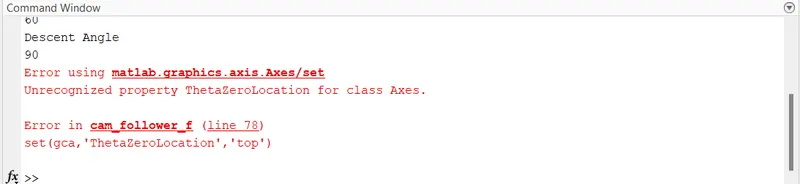
Soliving Errors-
- Removing typo errors
- use polarplot to plot figures
References -
- Theory of Machines book by R.S.Khurmi for cam and follower Motions.
- Mathworks Community
Conclusion -
The main motive of this script is to generate a cam and follower path while selecting a input angle and lift of follower and slection between various motion of followers. and it is succesfully achieved.