DESIGNING OF BUTTERFLY VALVE AND APPLYLING GD & TOLERANCE - NX CAD
OBJECTIVE :
The objective of this Project is to Design Butterfly Valve and apply GD & Tolerance to it using NX CAD as software tool.
INTRODUCTION:
A Butterfly Valve is from a family of valves called Quarter turn-valves. In operation, the valve is fully open or closed when the disc is rotated a quarter turn. The "butterfly" is a metal disc mounted on a rod. When the valve is closed, the disc is turned so that it completely blocks off the passeway. When the Valve is fully open, the disc is rotated a quarter turn so that it allows an almost unrestricted passage of the fluid. The valve may also be opened incrementally to throttle flow.
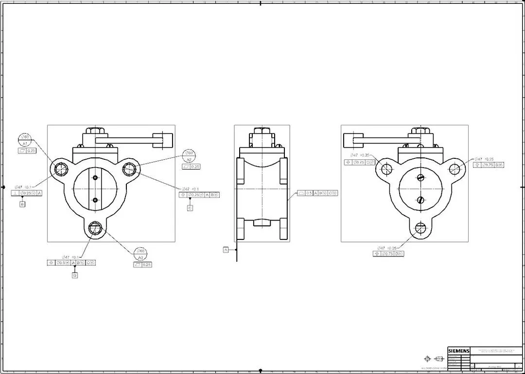
GEOMETRIC DIMENSIONING & TOLERANCE :
A Drawing which considers the function of the part and how this parts function with related parts is termed as "GD & T" . These Tolerances categorized into five groups - Form, Orientation, Location, run-outs, Location of derived median Points which are further divided into 14 types as per ASME Y14.5M- 2009. But as per latest ASME Y14.5 - 2018, Location of derived median points were expelled which left with 4 categories - 12 tolerances.
- Form - Straightness, Flatness, Circularity & Cylindricity.
- Orientation - Perpendicularity, Parallelism & Angularity.
- Runout - Circular run-out & Total run-out.
- Location - Position, Profile of a line & Profile of Surface.
Benefits of GD & T:
- Saving Money - GD & T enhances design accuracy by allowing for appropriate tolerances that maximize production. For many projects, the process provides extra or bonus tolerances, further increasing cost effectiveness.
- Offering uniformity and convenience - As a single, consistent language, GD & T reduces guess work and interpretation while ensuring consistent geometries across design and manufacturing.
- Assisting Digital Design Methods - Clear, concise GD & T data is readily adaptable to digital design programs, including nearly universally used 2D & 3D CAD files.
- Ensuring Dimensional and Tolerance Requirements - By explicity stating all design requirements, a thorough GD&T process guarantees accurate fulfillment of all dimensional and tolerance specifications.
- Providing Accurate Communication - Today's intricate designs demand the most accurate and reliable communication. GD&T enables designers, manufacturers and inspectors to communicate clearly with one other, saving time and making the process more efficient.
COMPONENTS OF BUTTERFLY VALVE:
- BODY
- SHAFT
- RETAINER
- DISC PLATE
- LEVER
- FASTNERS - NUT & SCREWS
WAY OF APPROACH:
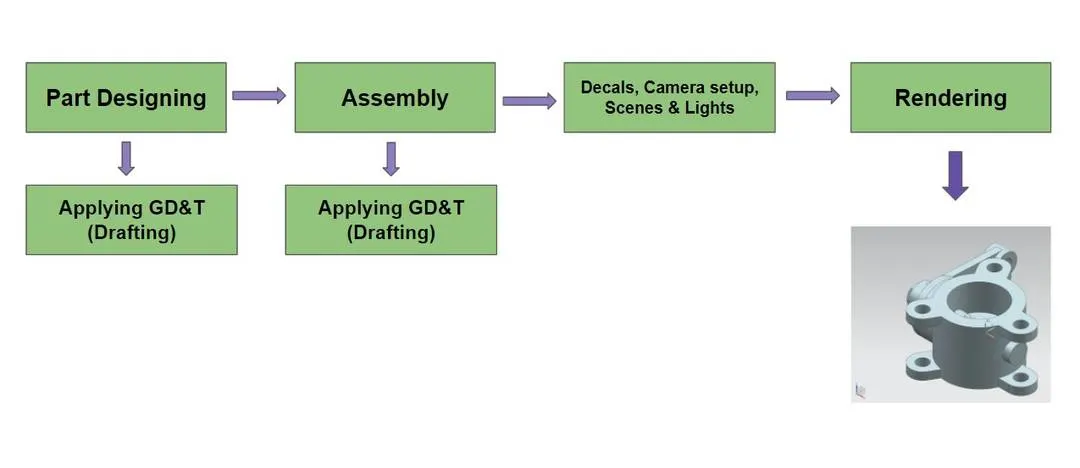
DESIGNING OF COMPONENTS:
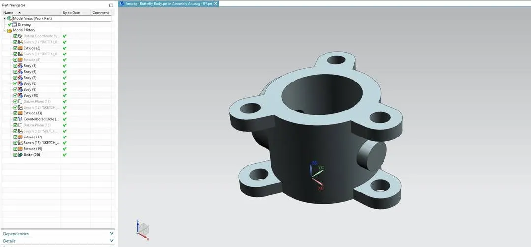
1. DESIGNING OF BODY - BUTTERFLY VALVE:
Butterfly Valves are usually fixed between two pipelines using flange couplings.
Feature Tools : Extrude, Counterbore hole, Unite, Datum Plane, Copy & move.
Sketch Tools : Line, Circle.
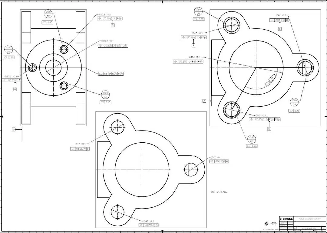
Drafting & applying GD & T:
GD & T Feature Tools : Datum Targerts, Datum Feature Symbols, Feature Control Frame, Cross hatch.
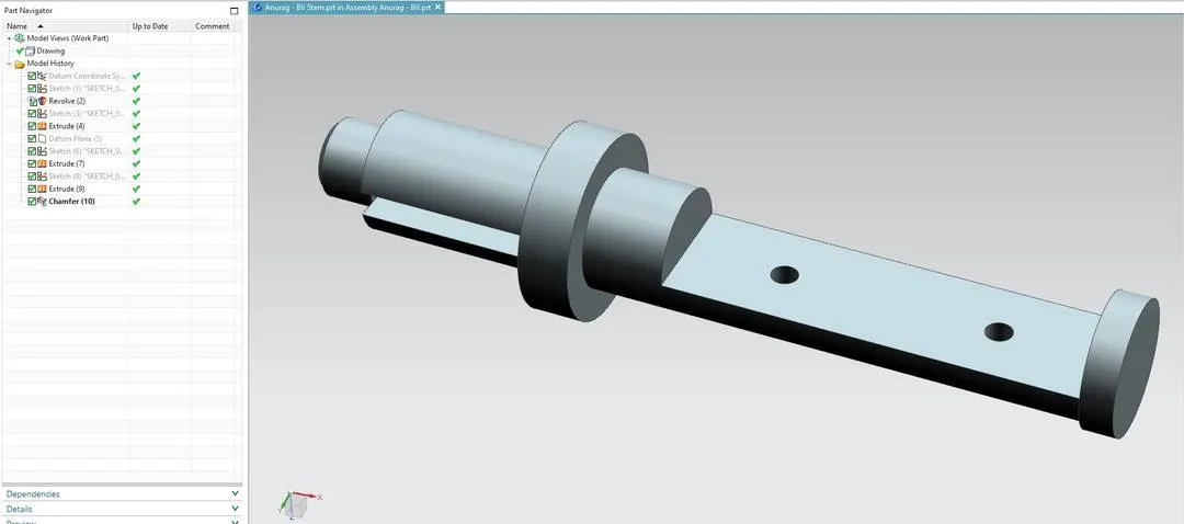
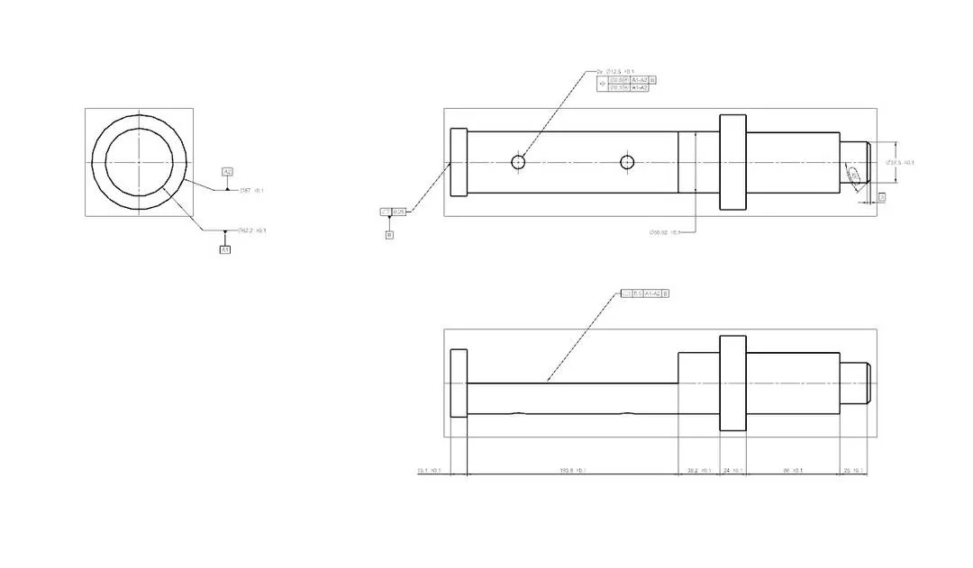
2. DESIGNING OF SHAFT/STEM - BUTTERFLY VALVE:
The disc/plate, lever and nut are assembled to shaft.
Feature Tools : Extrude, Revolve, Chamfer & Datum Plane.
Sketch Tools : Line, Circle, Arc., Trim & Extend entities.
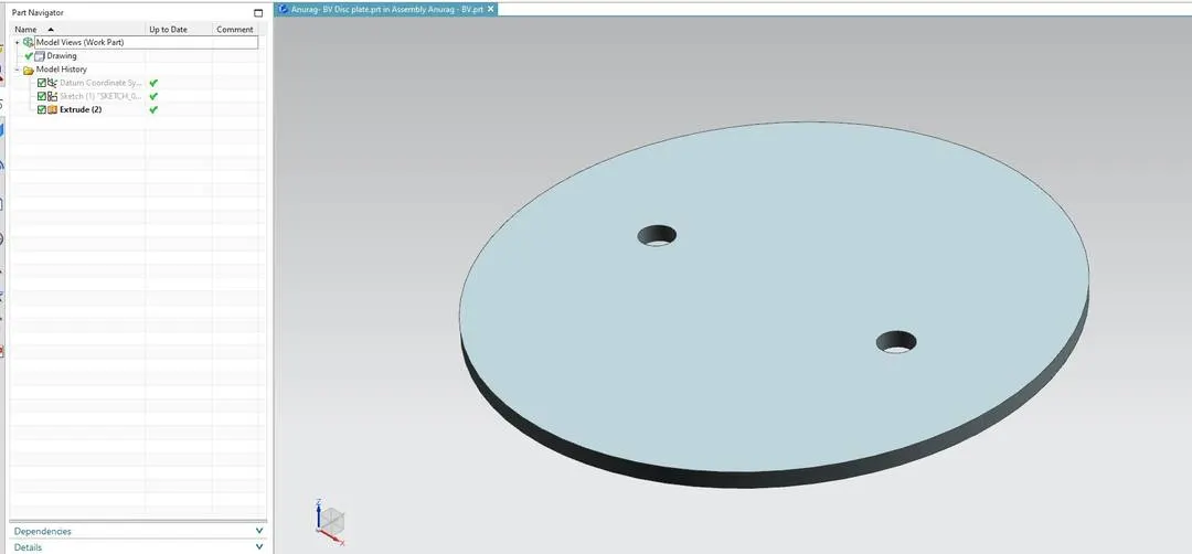
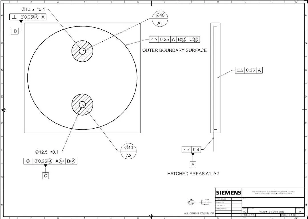
3. DESIGNING OF DISC - BUTTERFLY VALVE:
When the valve is closed, the disc is turned so that it completely blocks off the passeway. When the Valve is fully open, the disc is rotated a quarter turn so that it allows an almost unrestricted passage of the fluid
Feature Tools : Extrude.
Sketch Tools : Circle.
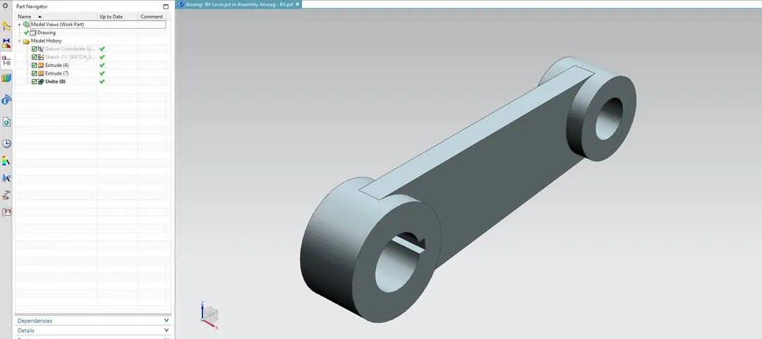
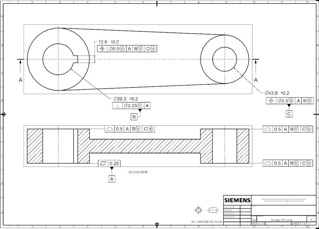
4. DESIGNING OF LEVER- BUTTERFLY VALVE:
Lever is mounted at the end of shaft outside the body. Hand lever is usually used in small sized Butterfly valves. It is used to open or close the valve.
Feature Tools : Extrude, Unite.
Sketch Tools : Line, Circle, Arc., Trim & Extend entities.
5. DESIGNING OF RETAINER - BUTTERFLY VALVE:
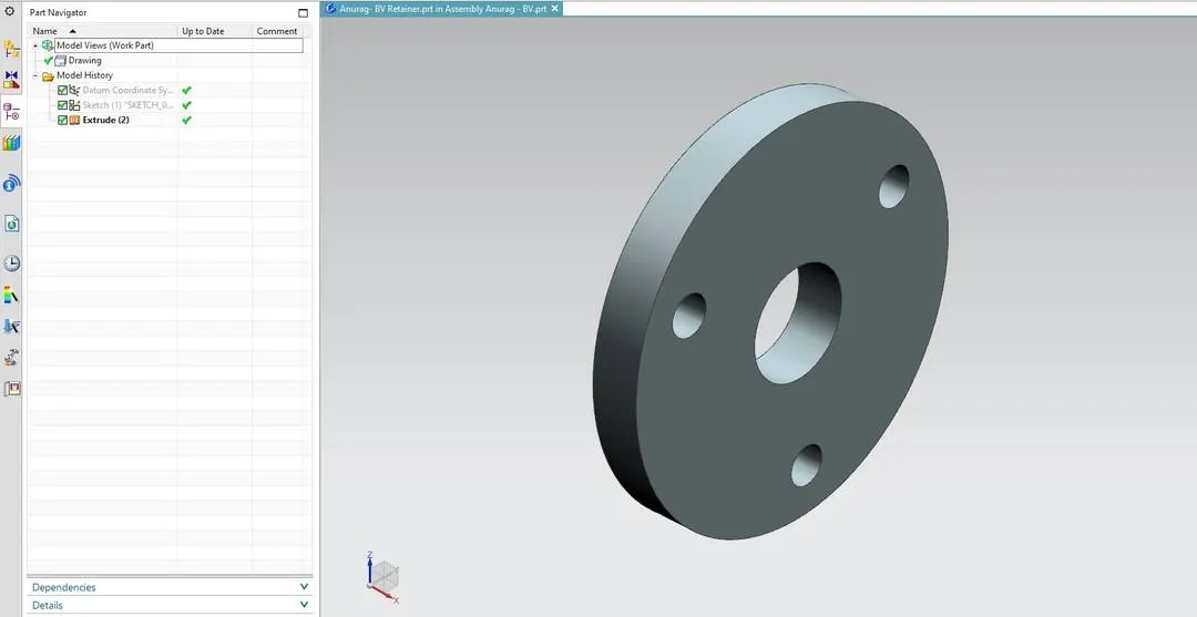
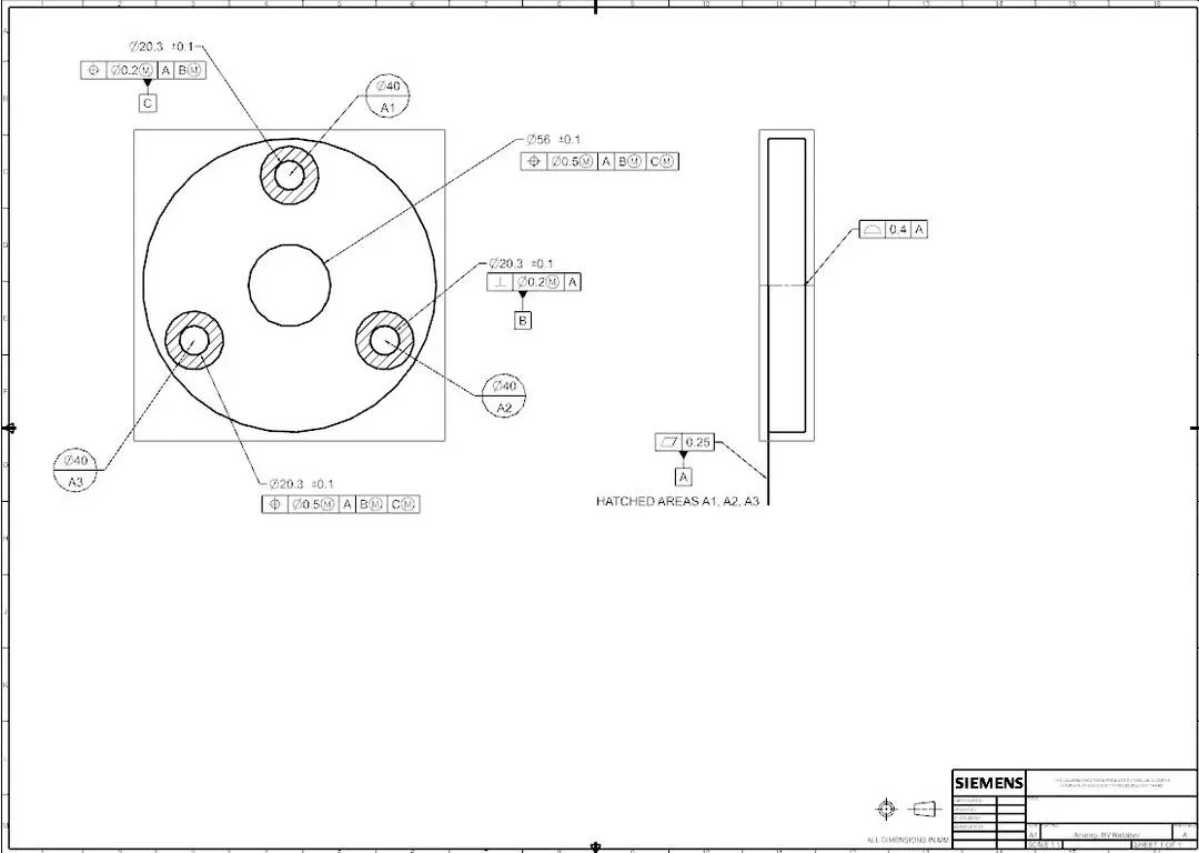
Retainer is a kind of washer fixed on the body of Butterfly Valve.
Feature Tools : Extrude.
Sketch Tools : Circle.
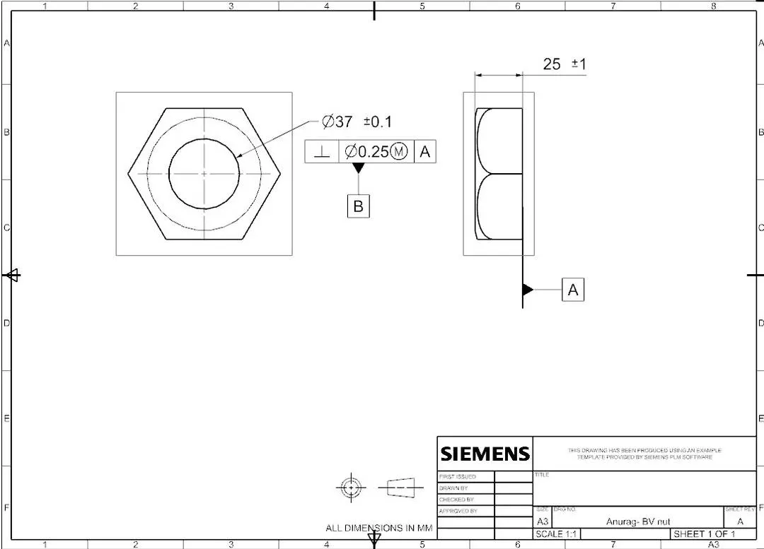
6. DESIGNING OF NUT - BUTTERFLY VALVE:
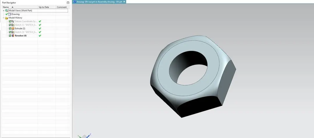
It is fixed at the top end of shaft to keep the lever and retainer on position relative to the body of butterfly Valve
Feature Tools : Extrude, Revolve.
Sketch Tools : Line, Circle, Arc, Fillet.
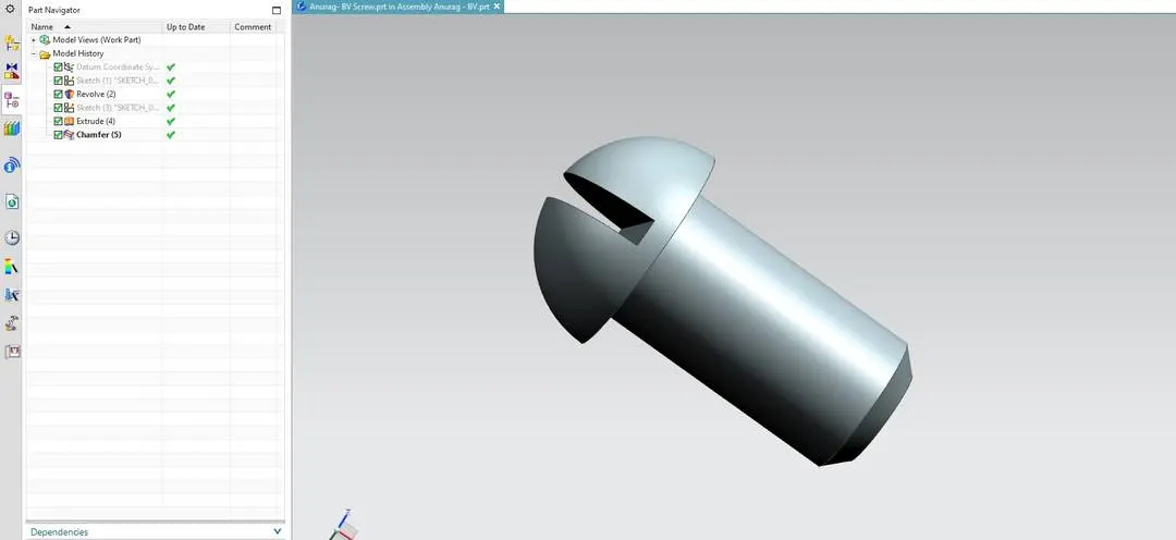
7. DESIGNING OF SCREW - BUTTERFLY VALVE:
Screw acts as fastners to attach the Disc to the stem/shaft as well as to fix retainer to body..
Feature Tools : Revolve, Extrude & Chamfer.
Sketch Tools : Line, Circle, Arc.
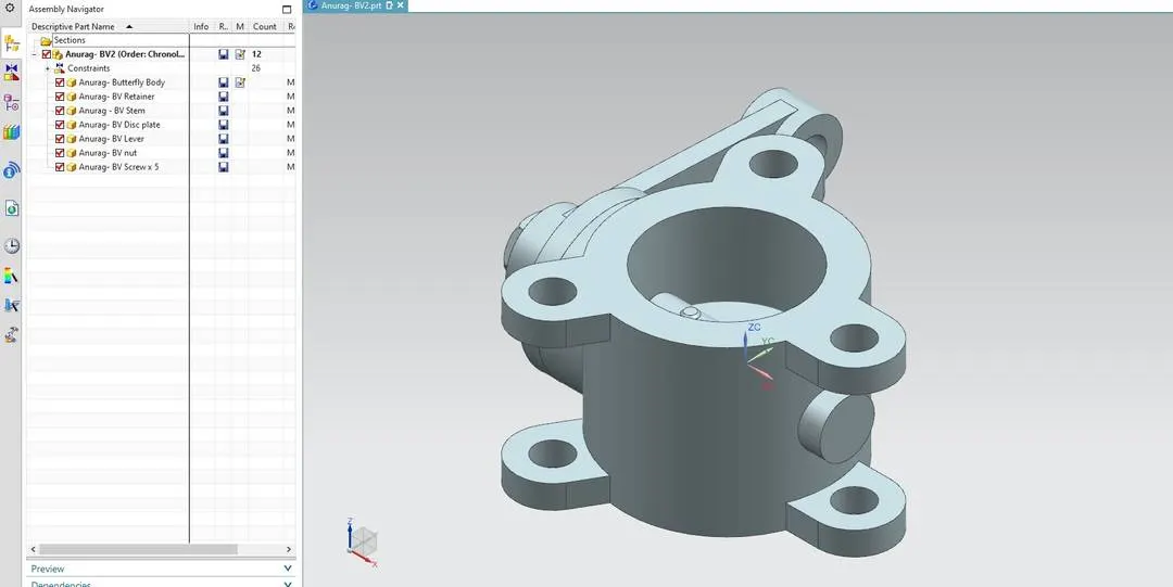
ASSEMBLY - BUTTERFLY VALVE:
Once all parts of Butterfly Valve were designed in Modelling, Assemble them by adding compponents in Assembly file. Give proper mates to all parts with eachother by fix Butterfly Body at the begining.
Mates: Align, Touch, Concentric.
RENDERING:
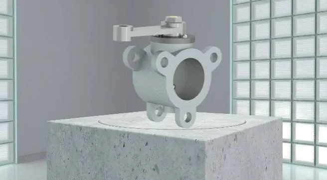
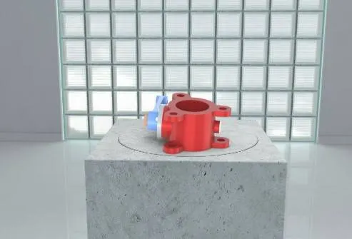
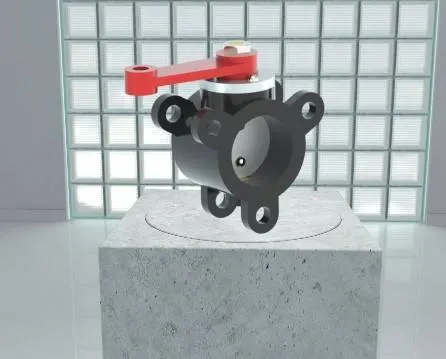
Add proper material to the Components and a Environment/Blackplate to give realistic look.
CONCLUSION:
At the end Modeling of Butterfly Valve is done by designing each and every component individually and getting together to assemble. GD & Tolerance given to components as well as Assembly using NX CAD Tool.