Designing of Buck converter
1- A DC/DC converter should be designed for an electric vehicle. The DC/DC converter should convert the voltage from the battery pack to 48 V to supply the 12 V loads (Radio, horn, accessories, etc..). The load needs an output current of 5 A. (Hint: the load can be represented as a resistance).
a) Draw a schematic of the DC/DC converter that you suggest for this application.
b) Specify the duty ratio of the converter.
c) Suggest a switching frequency of the converter.
d) Design the switching inductor such that the current is continuous and the inductor current ripple is less than 30% of the average inductor current.
e) Design the output capacitor such that the output voltage ripple is less than 5%.
f) What are the peak voltage and current values of your switches (Mosfet and Diode)?Comment from your simulation result
Your Answers
Designing of Buck converter:
1- A DC/DC converter should be designed for an electric vehicle. The DC/DC converter should convert the voltage from the battery pack to 48 V to supply the 12 V loads (Radio, horn, accessories, etc..). The load needs an output current of 5 A. (Hint: the load can be represented as a resistance).
a) Draw a schematic of the DC/DC converter that you suggest for this application.
b) Specify the duty ratio of the converter.
c) Suggest a switching frequency of the converter.
d) Design the switching inductor such that the current is continuous and the inductor current ripple is less than 30% of the average inductor current.
e) Design the output capacitor such that the output voltage ripple is less than 5%.
f) What are the peak voltage and current values of your switches (Mosfet and Diode)?Comment from your simulation result
Solution:
given,
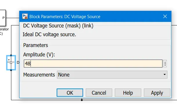
Vin = 48V
Vout = 12V
Output Current = 5A
inductor current ripple is less than 30% of the average inductor current
output voltage ripple of the capacitor is less than 5%.
Step of Designing:
Step 1: Draw a circuit Schematic diagram of the buck converter
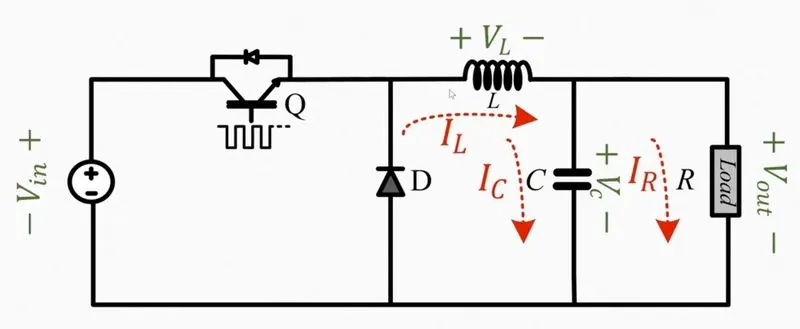
Step 2: Draw the Converter Circuit in ON & OFF mode.
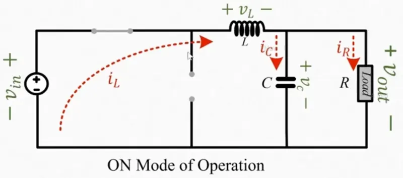
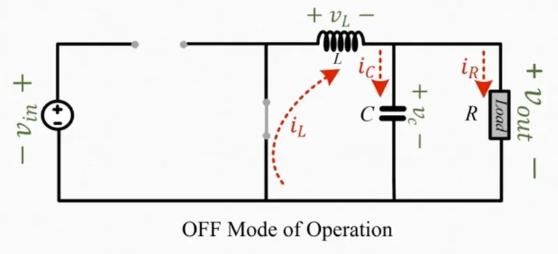
Step3: Calculation
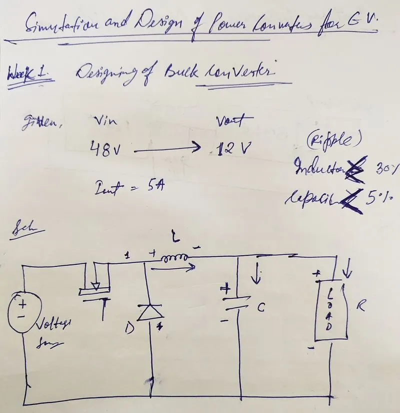
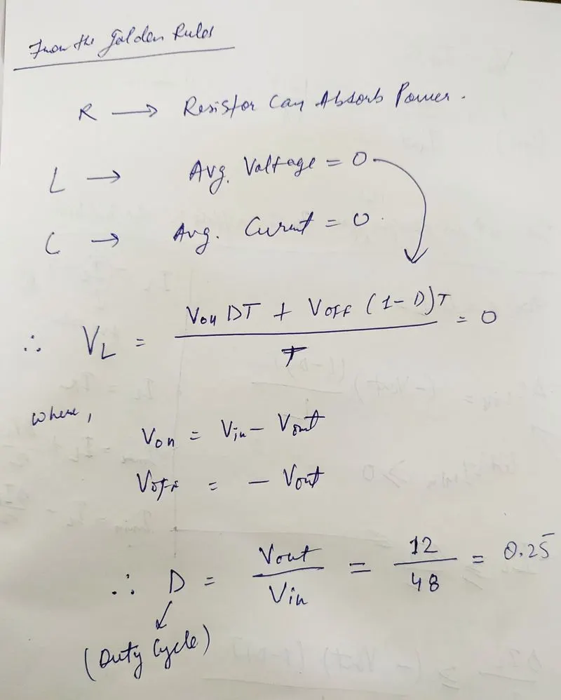
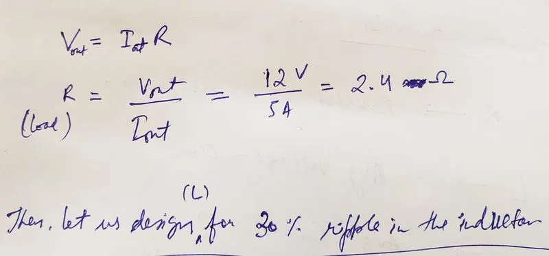
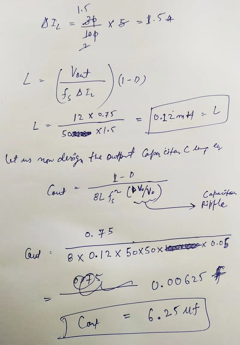
So, we got the values of,
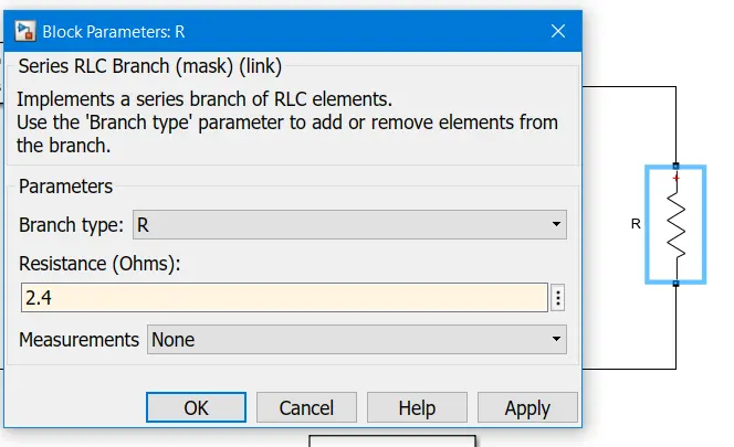
R = 2.4ohm
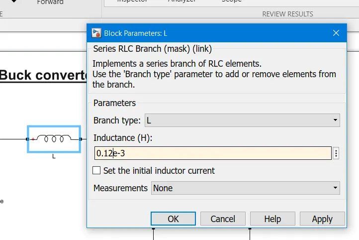
L = 0.12mH
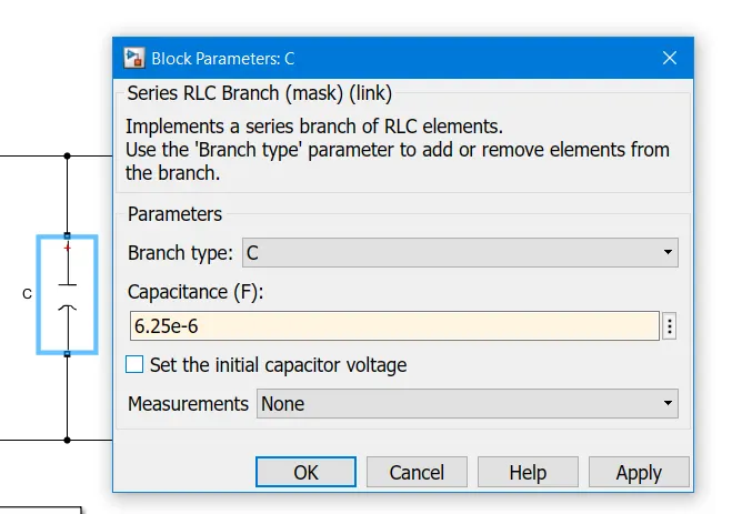
C = 6.25uf
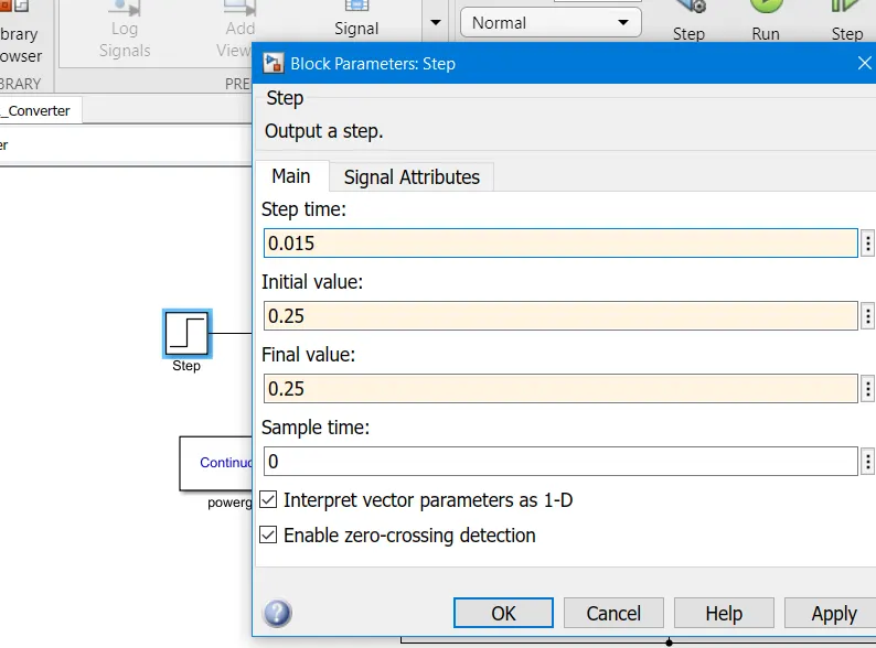
D = 25%
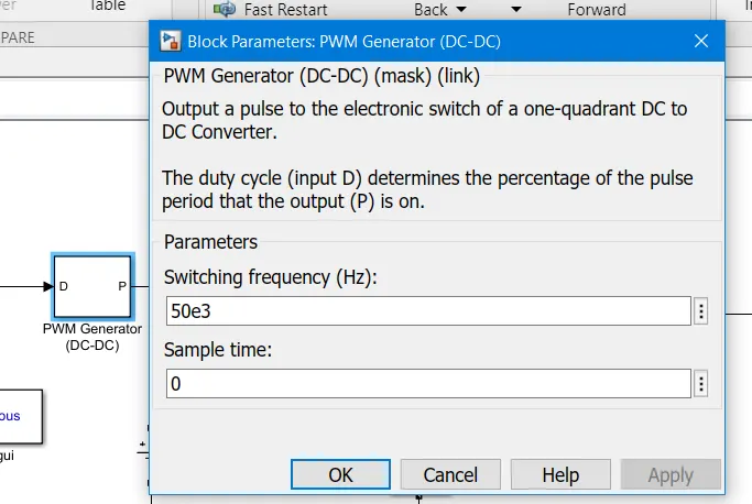
Assumption f= 50kHz
Step4: Now we have to design the circuit in MATLAB Simulink software to know the peak voltage and current values of my switches (Mosfet and Diode).
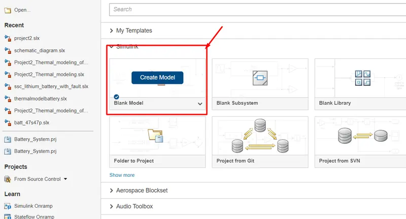
Open MATLAB and click on

Click on the Create Model.
Select all the required components like:
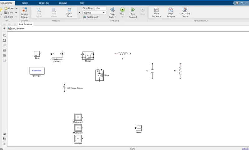
Step signal block, PWM Generator DC-DC, MOSFET, Diode, Voltage source, L, C, R, Scope, etc.
Now Configure each element according to our requirements.
Set R = 2.4ohm
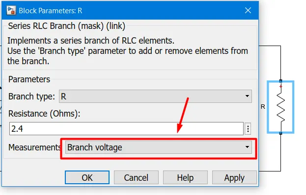
Enable Measurement to measure the Output Voltage.
Set Capacitance Value as calculated 6.25uf.
Set Inductance Value as Calculated 0.12mH with Measurement Enable for branch current.
Set Input Voltage 48V
Set Frequency to 50kHz as the supply frequency in India is 50kHz.
set Step block as the Duty cycle of 0.25.
configure the Multimeter block as we already activated the resistor branch voltage measurement and inductor branch current.
double-click on the multimeter block and select the signal accordingly.
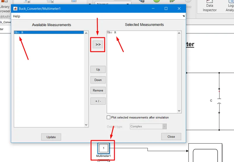
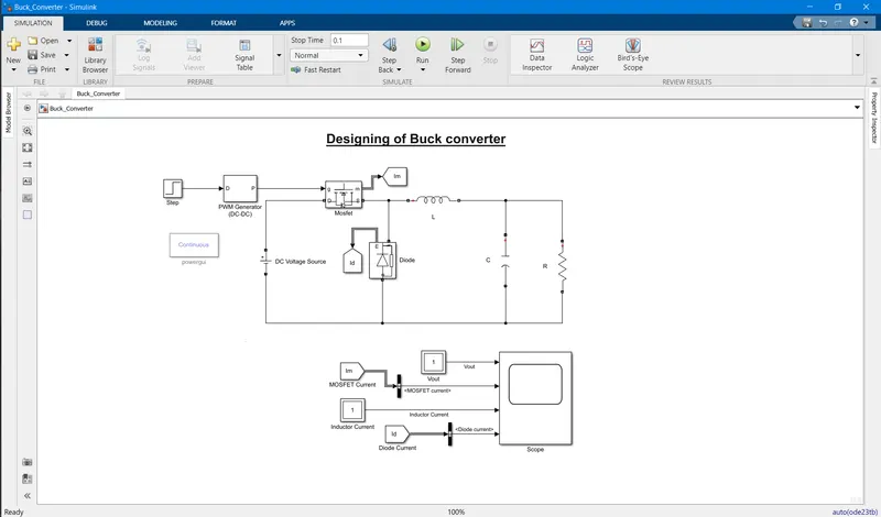
Now Connect everything according to the circuit diagram.
Zoomed Out and Zoomed In output graph.
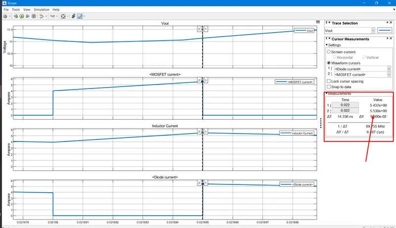
MOSFET Current and Diode Current
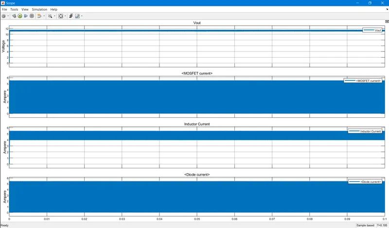
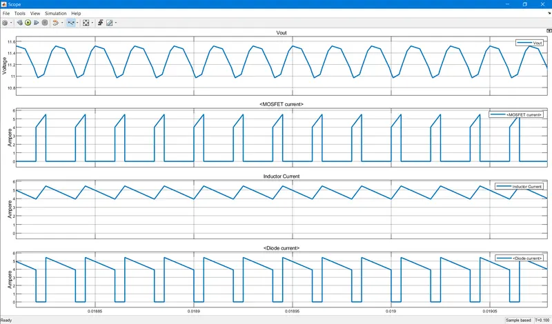
Zoomed Out and Zoomed In output graph.
MOSFET Voltage and Diode Voltage
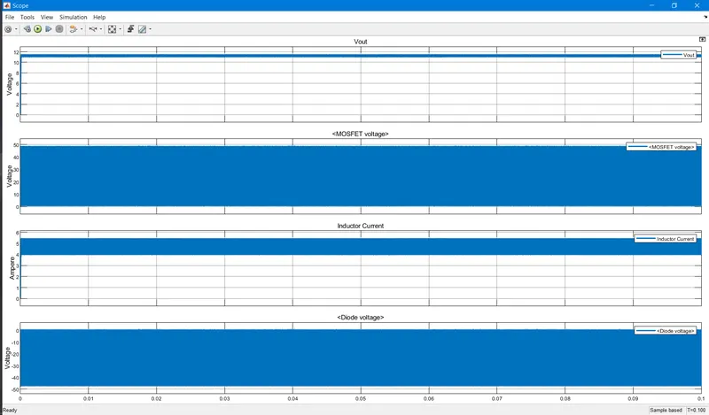
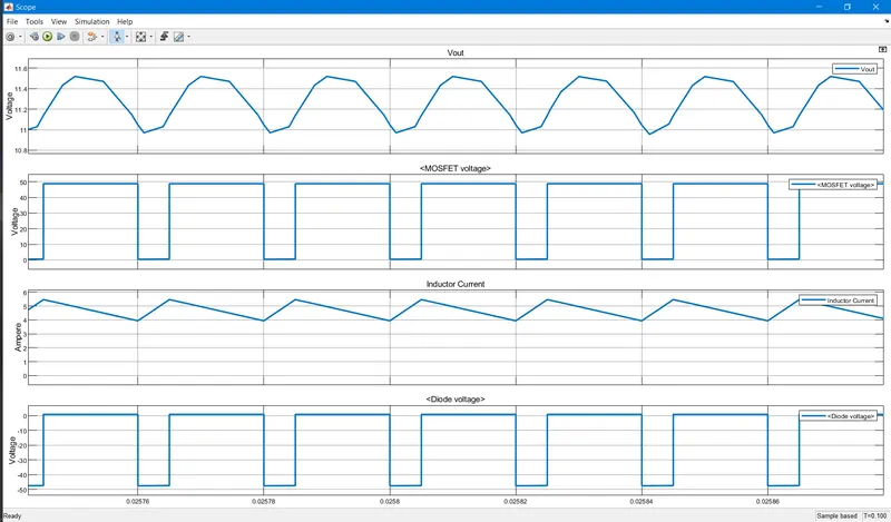
Comments:
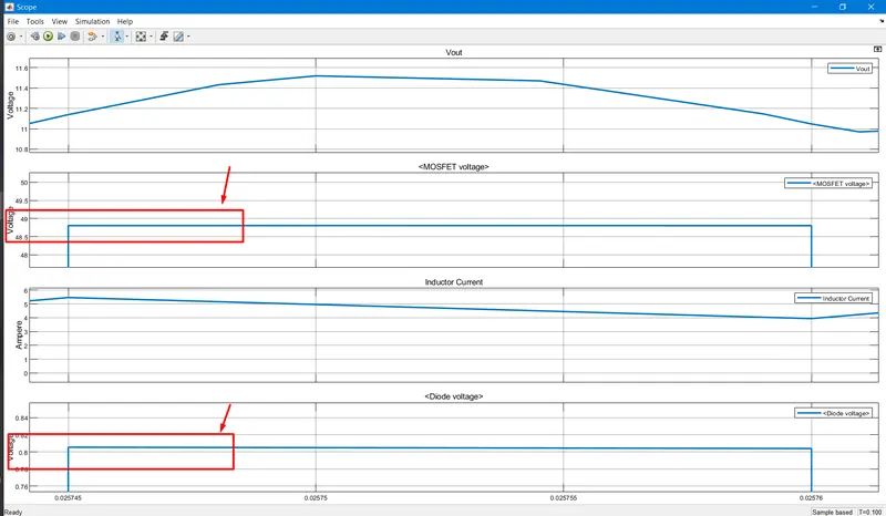
What are the peak voltage and current values of your switches (Mosfet and Diode)?
Peak Voltage of Mosfet = ~49V
Peak Voltage of Diode = ~0.8V
Peak Current of Mosfet = 5.5A
Peak Current of Diode = 5.4A
--------------------------------------------------------------------------------------------------------------------------------------------------------------------------------------------------------------------------END--------------------------------------------------------------------------------------------------------------------------------------------------------------------------------------------------------------------------------