Design of Shallow Foundation (Isolated Footings)
CHALLENGE WEEK 11
ETABS
Question no. 1: Design a square footing for a column size of 400x400. The compression axial load for the load combination of (1.5 DL + 1.5 LL) is 2000 KN. The safe soil bearing capacity is 150 KN/m2 at a depth of 2 metres below E.G.L. Participants are free to go for either a tapered or stepped footing. Besides the total axial load, also account for the self-weight of the footing and soil above it. Assume M25 concrete grade. Do the following checks:
Answer:
- AIM:
- To design a square footing with said dimensions
- To carry out manual calculation using relative code provisions
- Procedure:
- Calculation of Gross soil pressure & Footing area:
- Unfactored load with surcharge + self weight of footing/allowable soil pressure
= (2000/1.5 * 1.1)/150 = 9.78 m2
Assuming we have square footing
(As we do not have height of footing we are assuming certain parameters and finding it to proceed the design)
√9.78 = 3.12 meter side footing
Consider , 3.2 meter sided isolated footing from the calculation
- Calculation of net soil pressure & initial footing depth
- Factored load/actual area of footing
=2000/(3.2*3.2)
Pn = 195.3 KN/m2
- Assume depth of footing 500mm and checking it for bearing stress as per IS 456-2000 Clause 34.4
√(footing base bearing area/loaded area)≤2
- Permissible bearing stress 0.45*Fck = 11.25N/mm2
- Permissible bearing stress multiplied with area factor = 11.25*2 = 22.5N/mm2
- Actual bearing stress at column base
(2000*1000)/(400*400) = 12.5 N/mm2
12.5N/mm2 actual stress is less than permissible 22.5N/mm2 . Hence Okay
- We can proceed with 500mm depth footing for furthur design checks.
- If we assume 50mm cover for footing, the effective depth(d) shall be taken as 450mm
- Flexural reinforcement design calculation:
- Conversion of net pressure into uniformly distributed load = 195.3*3.2 = 625KN/m
- Bending moment due to UDL over a cantilever section = WL2/2 = 625*1.6*1.6/2
M = 800KNm
- Reinforcement calculation as per IS 456-2000 Annex-G
Mu = 0.87fy Ast d (1-((Ast fy)/(bd fck))
- Assume fy=500N/mm2, in result Ast required = 4350mm2
- If we provide 16mm dia bars at 125mm spacing, the actual rebar provided = 3200/125 * 201
Ast provided = 5146mm2
Here Ast provided is greater than Ast required but still as we cannot increase spacing too much and 125mm spacing is reasonable we can go with the above calculation
- One way shear stress check:
- Shear force in the one way slab area in the reaction of load = 0.95 * 3.5*195.3=593.7KN
- Design shear stress at one way cut face
Τv =593.7*1000/(3200*450)=0.412N/mm2
- Shear stress capacity of section as per IS 456-2000 Table-19(include bar) = 0.425N/mm2
- Design shear stress is less than shear capacity
- Hence okay
- Two way shear stress check:
- Shear force in the two way loaded area = (3.2*3.2)-(0.85*0.85)*195.3 = 1859KN
- Design shear stress at two way cut face
Τv =593.7*1000/(3200*450)=0.412N/mm2
- Shear stress capacity of section as per IS 456-2000 Clause 31.6.3.1= 0.25*√Fck = 1.25N/mm2
- Design shear stress is less than shear capacity.
- Hence okay
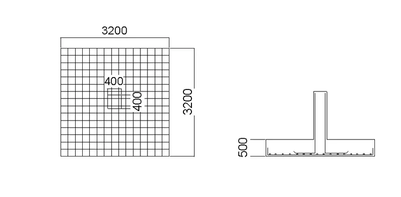
- Detail drawing of footing
- Here we are providing normal straight footing without using any stepped footing because when we use stepped footing or sloped footing the depth gets too small which may not be compatible for one way and two way shear satisfaction hence we have used straight single footing
- Thus designed and drafted footing is shown below
- Result:
- We have designed the said footing
- Manual calculations were done and presented.