Design of Shallow Foundation (Isolated Footings)
Q.1. Design a square footing for a column size of 400x400. The compression axial load for
the load combination
of (1.5 DL + 1.5 LL) is 2000 KN. The safe soil bearing capacity is 150 KN/m2 at a depth of 2
metres below E.G.L. Participants are free to go for either a tapered or stepped footing.
Besides the total axial load, also account for the self-weight of the footing and soil above
it. Assume M25 concrete grade. Do the following checks:
- If the gross bearing pressure under the footing is within safe bearing capacity
- Provide sufficient depth and longitudinal steel for resisting bending and shear
- Sufficient anchorage for column steel into the footing
- If the bearing pressure at column-footing joint is within 0.45 times the
maximum concrete compressive strength
Provide a simple sketch showing the size of the footing, maximum and minimum depth
of the section, flexural reinforcement in both directions and anchorage of column steel.
Ans:-
DESIGN OF SHALLOW FOUNDATION ISOLATED FOOTING
Aim:-
To design a square footing for a column of size 400x400 using some of the informations such as
- The compression axial load for the load combination of (1.5 DL + 1.5 LL) = 2000 KN.
- The safe soil bearing capacity = 150 KN/m2 at a depth of 2 metres below E.G.L.
- Grade of concrete = M25
Then to perform the following checks:
- Calculation of gross soil pressure for footing area.
- Calculation of Net soil pressure for flexure and shear design
- Provide sufficient depth and longitudinal steel for resisting bending and shear
- Sufficient anchorage for column steel into the footing
- If the bearing pressure at column-footing joint is within 0.45 times the maximum concrete compressive strength
- One way shear check.
- Two way shear check.
Introduction:-
- Footings and other foundation units transfer loads from the structure to the soil or rock supporting the structure.
- The distribution of soil pressure under a footing is a function of the type of soil and the relative rigidity of the soil and the foundation pad.
- Most common types of footings used are:
- Strip or wall footing
- Spread footing
- Stepped footing
- Tapered footing
- Pile cap
- Combined footing
- Mat or raft footing.
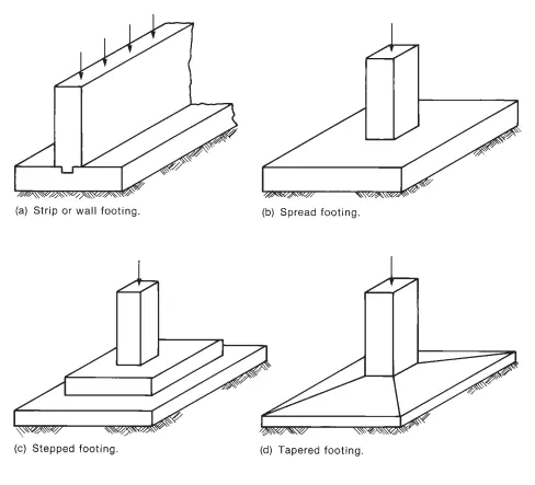
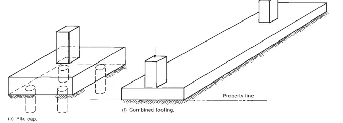
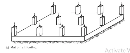
- This project is dealing with isolated footing for a column or spread footing.
Procedure:-
- - Given datas include:-
- Column size = 400mmx400mm
- Compression axial load (1.5DL+1.5LL) = 2000kN - factored load
- Safe bearing capacity of soil at a depth of 2m below EGL = 150kN/m2�2
- Assuming the self weight of footing and soil above it as 10% load.
- Assume soil density = 20 KN/m^3
- Grade of concrete = 25kN/m2�2
- Assuming fy = 500N/mm2��2
- Here a sloped footing is designed and the steps involved in the design are as follows:
1) Size of footing:-
Calculation of Gross soil pressure:
Unfactored load = 2000/1.5 = 1333 kN
Assume thickness of footing (t) = 0.5 m
Depth of footing as given in data (h) = 2 m, So soil surcharge depth = 2 - 0.5 = 1.5 m
Assume soil density = 18 kN/cu.m
Assume RCC density = 25 kN/cu.m
Consider square shape footing, area of the Footing = b x b = b2�2
Unfactored or service load = 20001.5=1333.33kN20001.5=1333.33��
Safe bearing capacity of soil/gross soil pressure , qc = 150kN/m2�2
Footing area = (Unfactored load with surcharge X self weight of footing)/allowable soil pressure
Hence, the required base area = 1333.33⋅1.1150=9.78m21333.33⋅1.1150=9.78�2
Hence, provide 3200mmx3200mm which gives 10.24m2�2 base area for footing. (This area later proves to be insufficient).
2) Net Soil Pressure & Initial footing depth:-
Net soil pressure= Factored Load/Actual area of footing
= 2000/(3.2 X 3.2)= 195.312 KN/m2 or 0.195 N/mm^2
Assuming the depth of footing 500mm and checking it for bearing stress as per IS:456-2000 Clause 34.4
Permissible bearing stress = 0.45 X fck = 0.45X25= 11.25 N/mm2
Permissible bearing stress multiplied with area factor= 11.25X2 = 22.5 N/mm2
Actual bearing stress at column base= (2000X1000)/(400X400)= 12.5 N/mm2
12.5 N/mm2 actual stress is less than permissable 22.5 N/mm2. Hence Okay.
We can proceed with 500mm depth footing for further design checks.
If we assume 50mm cover for footing, the effective depth D shall be taken as 450mm.
3) Flexural reinforcement:-
Conversion of net pressure into uniformly distributed load = 195.312 X 3.2 = 624.99~ 625 KN/m
Bending moment due to UDL over a cantilever section = wL^2/2 = (625X1.6X1.6)/2 = 800 KNm
Reinforcement calculation as per IS:456-2000 Annex G
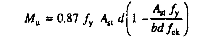
Back calculation in excel file-
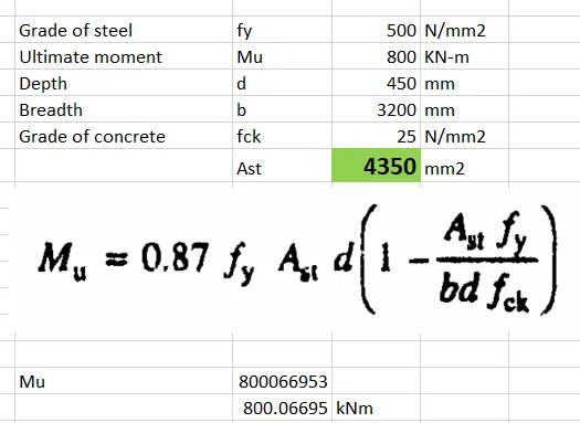
Assume fy= 500 N/mm2, After solving this equation value of Ast= 4350 mm2
If we provide 16mm dia rebar at 125mm spacing, the actual rebar provided = (3200/125) X 201 = 5146 mm2.
4) One way shear stress check:-
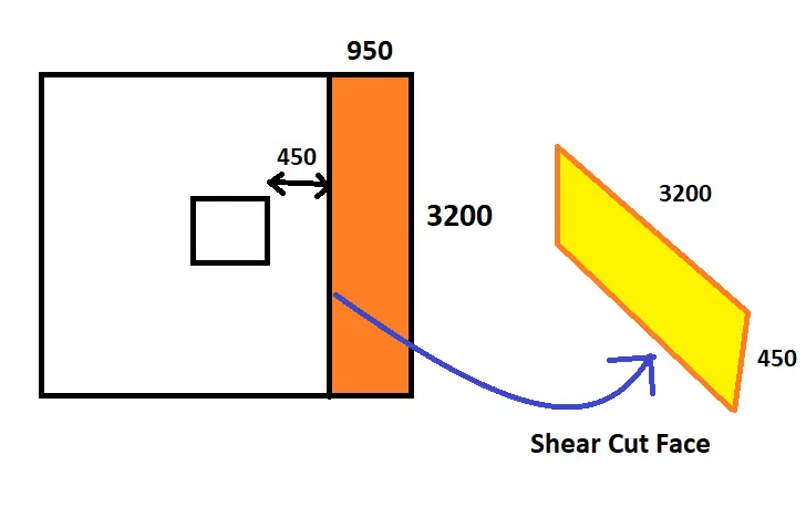
Shear force in the one way shaded area = 0.95 X 3.2 X 195.3 = 593.7 KN
Design shear stress at one way cut face (τv��) = (593.7 X 1000)/(3200 X 450)= 0.412 N/mm^2
Shear force capacity of section as per IS-456-2000 Table-19 (Include rebar) = 0.444 N/mm^2 (By Interpolation method)
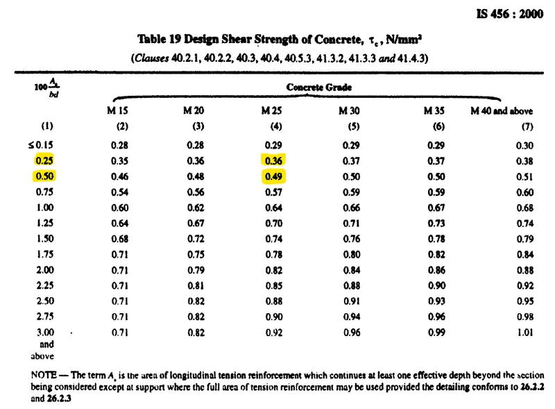
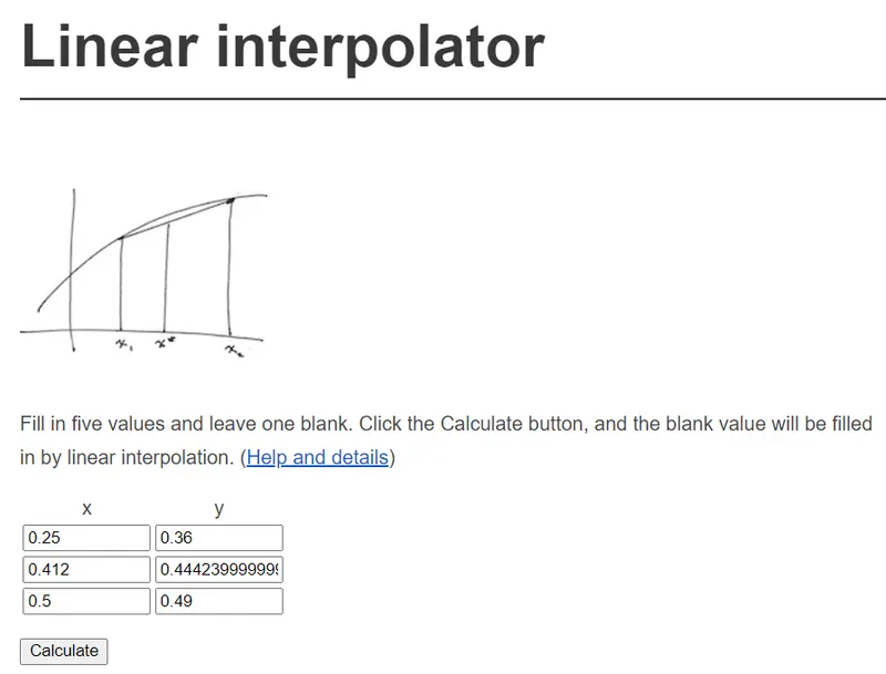
Design shear stress is less than shear capacity.
Hence Okay.
5) One way shear stress check:-
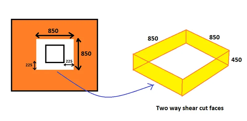
Shear force in the two way shaded area= [(3.2X3.2)-(0.85X0.85)] X 195.3 = 1858.77 ~ 1859 KN
Design shear stress at two way cut face τv��= (1859X1000)/(3400X450) = 1.215 N/mm^2
Shear stress capacity of section as per IS-456:2000 Clause 31.6.3.1 

Design shear stress is less than shear capacity.
Hence okay.
7) Gross bearing capacity:-
Assuming unit weight of concrete and soil as 25kN/m3�3 and 18kN/m3�3, we have,
Load on footing = 1333.3kN
Weight of footing = 3.2x3.2x0.7x25=179.2kN
Weight of soil = 3.2x3.2x(2-0.7)x18=239.61kN
Total load = 1333.3+179.2+239.61 = 1751.81kN
Hence, gross bearing capacity = 1751.813.2⋅3.2=171.071751.813.2⋅3.2=171.07kN/m2�2 > 150kN/m2�2.
Hence, we need to increase the size of footing to 3600mmx3600mm.
So, now the weight of footing = 3.6x3.6x0.7x25 = 226.8kN
Weight of soil = 3.6x3.6x(2-0.7)x18=239.61 kN = 303.26kN
Total load = 1333.3+226.8+303.26 = 1863.06kN
Now, gross bearing capacity = 1863.063.6⋅3.6=143.751863.063.6⋅3.6=143.75kN/m2�2<150kN/m2�2.
Hence safe.
So, the corrected net soil pressure = 20003.6⋅3.6=154.3220003.6⋅3.6=154.32kN/m2
Re-Design of Footing:-
- Bending moment:-
We need to determine the area of steel in one direction as it is a square footing.
If we assume 50mm cover for footing, the effective depth D shall be taken as 450mm
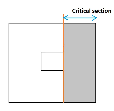
Net soil pressure= Factored Load/Actual area of footing
= 2000/(3.6 X 3.6)= 154.321 KN/m2 or 0.154 N/mm^2
Conversion of net pressure into uniformly distributed load = 154.321 X 3.6 = 555.555~ 556 KN/m
Bending moment due to UDL over a cantilever section = wL^2/2 = (556X1.8X1.8)/2 = 900 KNm
Reinforcement calculation as per IS:456-2000 Annex G
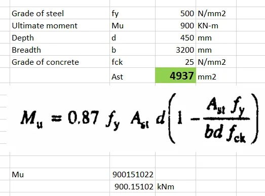
Assume fy= 500 N/mm2, After solving this equation value of Ast= 4937 mm2
So, no. of bars required is given by, 4937314=15.72~164937314=15.72~16bars
Hence, provide 16 nos of 20mm dia bars both ways.
If we provide 20mm dia rebar at 225mm spacing, the actual rebar provided = (3200/225) X 314 = 5024 mm2.
- One way shear stress check:-
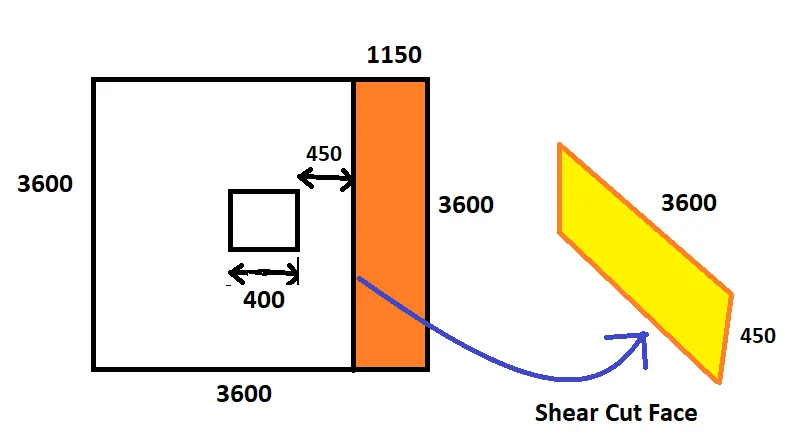
Shear force in the one way shaded area = 1.15 X 3.6 X 154.321 = 638.888 KN ~ 639 KN
Design shear stress at one way cut face (τv��) = (639 X 1000)/(3600 X 450)= 0.394 N/mm^2
Shear force capacity of section as per IS-456-2000 Table-19 (Include rebar) = 0.434 N/mm^2 (By Interpolation method)
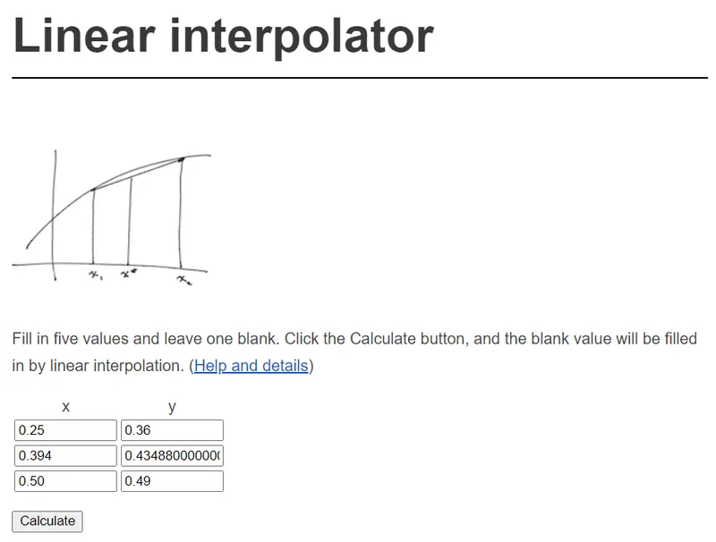
Design shear stress is less than shear capacity.
Hence Okay.
- One way shear stress check:-
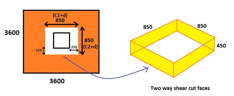
Shear force in the two way shaded area= [(3.6X3.6)-(0.85X0.85)] X 154.321 = 1888.503 ~ 1889 KN
Design shear stress at two way cut face τv��= (1889X1000)/(3400X450) = 1.234 N/mm^2
Shear stress capacity of section as per IS-456:2000 Clause 31.6.3.1
Design shear stress is less than shear capacity.
Hence okay.
Result:-
Sloped isolated footing for a square column has been designed with the given specification
Calculation of Stepped footing:-
Critical distance of Oneway shear from column face = 450mm
Critical distance of Twoway shear from column face = 225mm
We have to provide 500mm footing thickness at least 450mm from column face, rounding it off to 500mm
uniform around the column, as shown below.
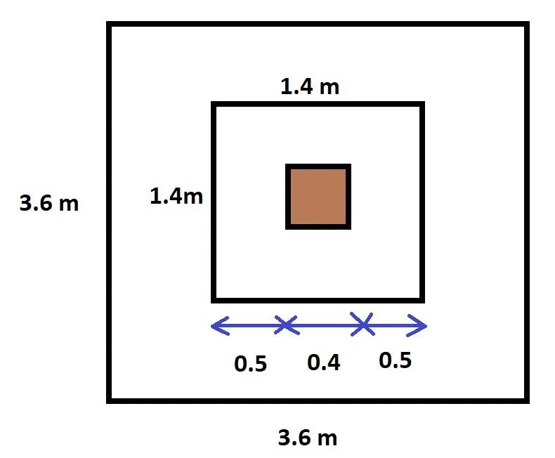
Schematic Representation of Footing step and reinforcement:
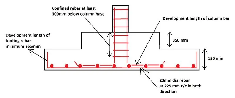
Conclusion:-
Thus the required spread footing is designed and detailed as per given inputs. All the reuired
limite state criteria are verified and found to OK.