DESIGN OF DOOR TRIM
DESIGN OF DOOR TRIM
Objective:
With the input of class A surfaces and master sections, the plastic door trim parts are to be developed by using the 'Generative shape design' workbench in CATIA V5. Performing the 'Draft Analysis' on the solid part body of the Door trim.
Overview:
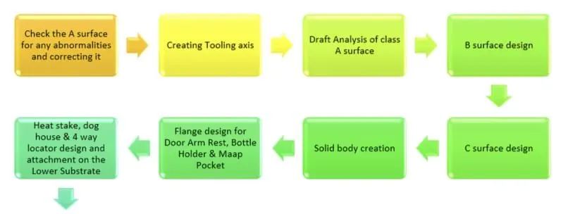
Initially, we need to offset the given Door Trim class A surface in the inner direction to the required thickness (here the thickness is 2.5mm). After that, we need to close the patches on the offset surface of the door trim, the patches are formed due to the fillets on the Class A surface. Once all the patches are closed properly join them together to make a proper class B surface and now sweep the boundary of the class A surface to trim with the class B surface to make a closed body. By using the closed body command in the Prat workbench we can get the solid body from the closed surface of the Door Trim. Now, I created the Heat stakes and Locators by considering all the design parameters. After creating all the B-side features on the solid part body of the door trim, I performed a draft analysis for it to check whether all the surfaces are drafted properly or not (The draft angle for the plastic component is 0.5deg to 3deg).
Design Methodology:
For this project we need to design four parts of the door trim using the master sections provided, namely
- Door Arm Rest
- Lower Substrate
- Bottle Holder
- Map Pocket
Tools Used:
Part workbench:
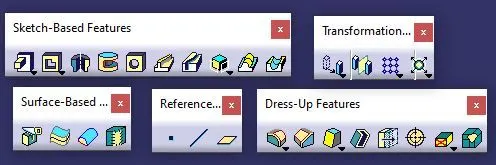
Surface Workbench:

TOOLING AXIS:
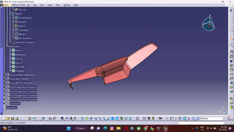
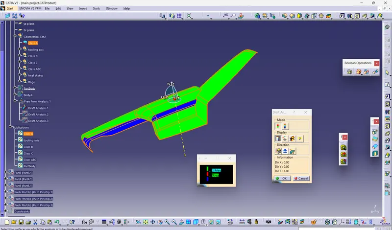
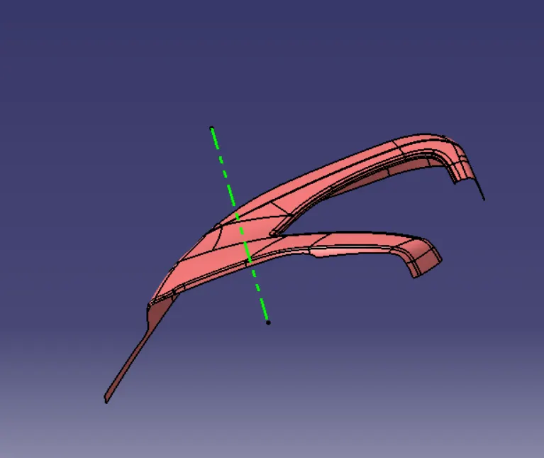
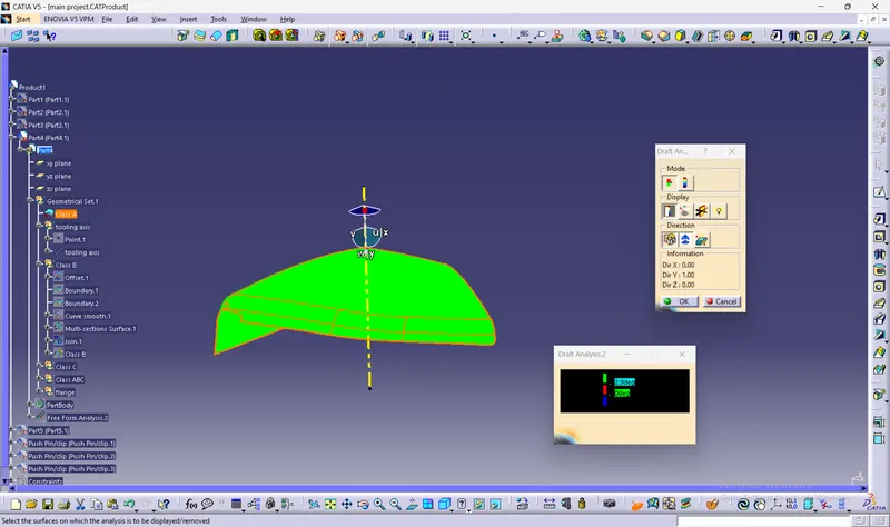
To create the tooling axis, I extracted a surface from class A and created a point in the middle of the surface by using the point command and created a line at that point through the x-axis. Now, I performed a draft analysis check from that line whether the created tooling axis is in the correct position or not. If in the draft, analysis check the surface highlighted with green colour on both sides of the surface the tooling axis is in the correct position and direction.
Draft Analysis:
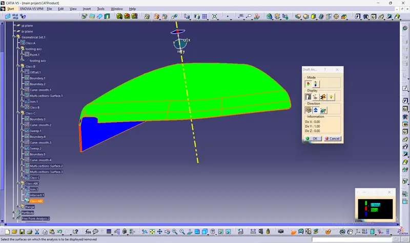
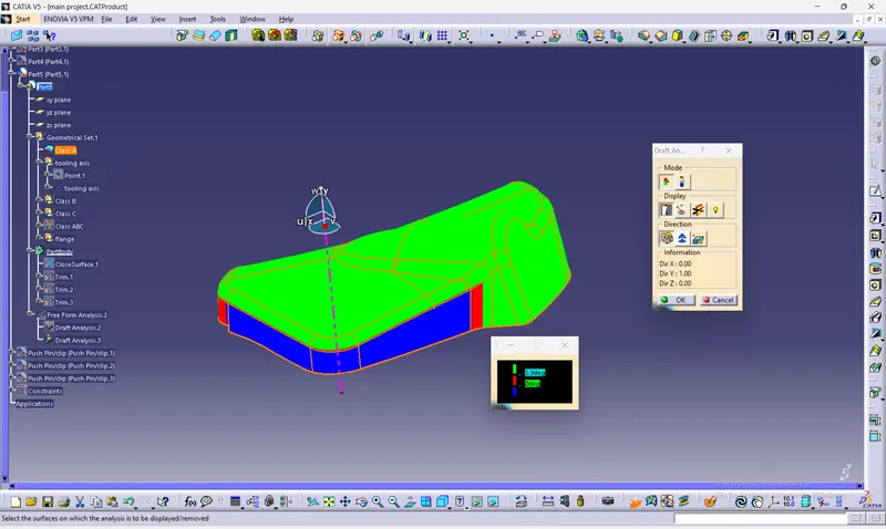
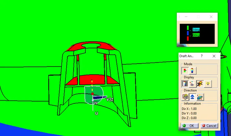
Draft analysis measures the draft angle on multiple surfaces of a part along the tooling axis to check if the surfaces have the minimum required draft angle for it to be moulded properly.
CLASS B SURFACE:
To create the class B surface, offset the class A surface inside as per our thickness requirement (here the thickness is 2.5mm, so I offset the class A to 2.5mm inside). Once the offset is created, we can observe some patches on the offset surface by taking the boundary for the offset surface, those patches are formed due to the fillets on the class A surface. We need to cover those patches with the help of the multi-section surfaces command by extracting the patch boundaries. Once all the patches on the offset are covered properly join all the patches with the offset surface, to get the replicated surface of the class A surface.
CLASS C SURFACE:
The surface that joins class-A and class-B surfaces are class-C surfaces. Class C is often specified for interior surfaces not readily visible, surfaces that will be covered by another part when assembledThe Class C finish allows more imperfections than Class A or B. Class C is often specified for interior surfaces not readily visible, surfaces that will be covered by another part when assembled, or surfaces which the Customer feels do not need to meet a high cosmetic finish.
Door Arm Rest:
class a surface:(DOOR ARM REST)
Tooling axis:
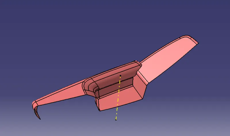
class c surface:(DOOR ARM REST)
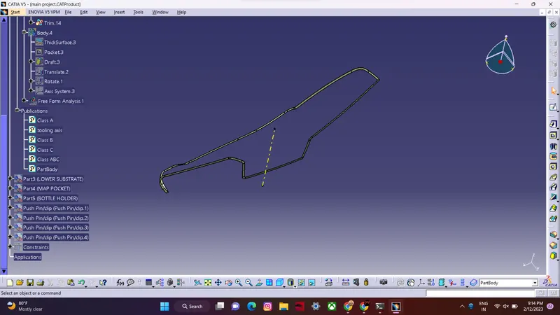
class b surface :(DOOR ARM REST)
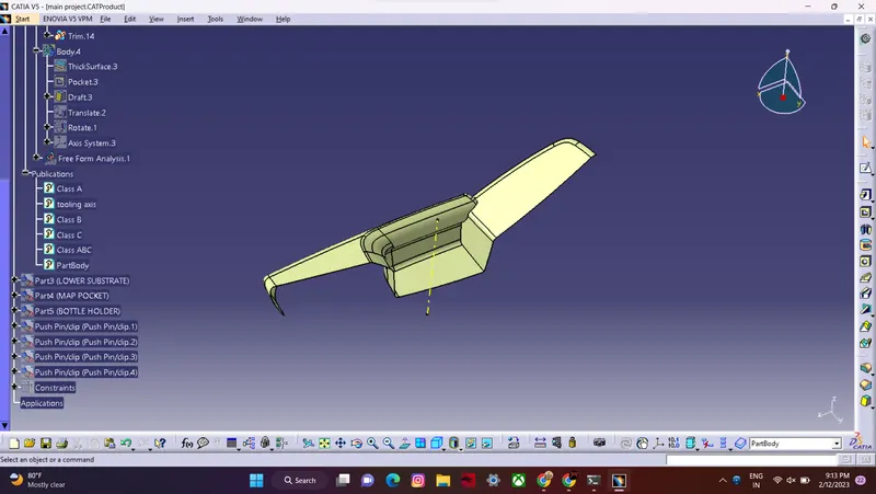
class ABC surface:(DOOR ARM REST)

part Body:(DOOR ARM REST)
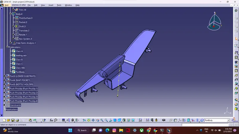
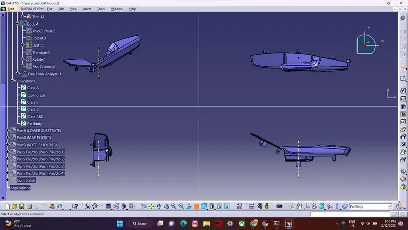
DRAFT ANALYSIS:(DOOR ARM REST)
Lower Substrate:
class A surface:(Lower Substrate)
Tooling Axis:
class B surface:(Lower Substrate)
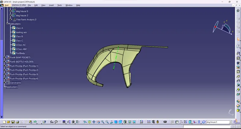
class C surface:(Lower Substrate)
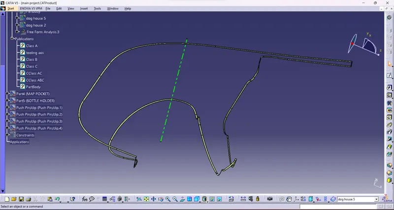
class ABC surface:(Lower Substrate)
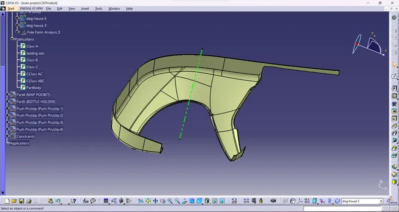
PART BODY:(Lower Substrate)
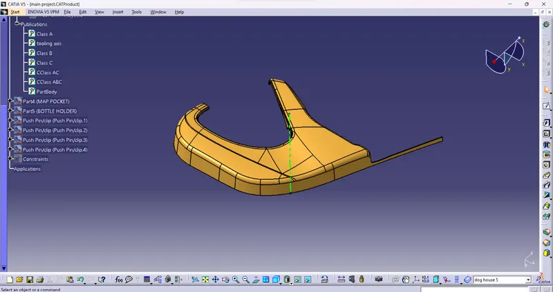
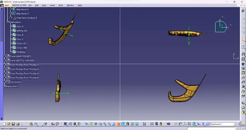
DRAFT ANALYSIS:(Lower Substrate)
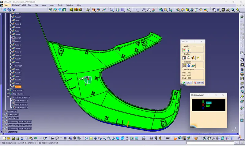
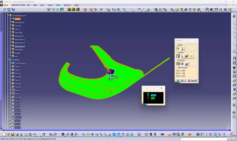
Bottle Holder:
Class A Surface :(Bottle Holder)
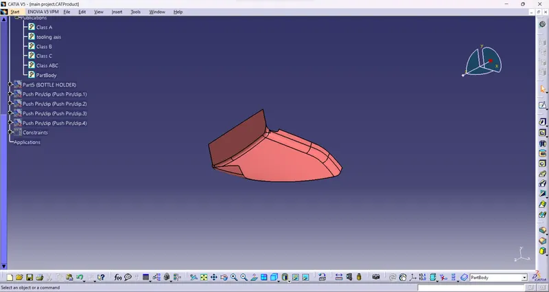
Tooling Axis:(Bottle Holder)
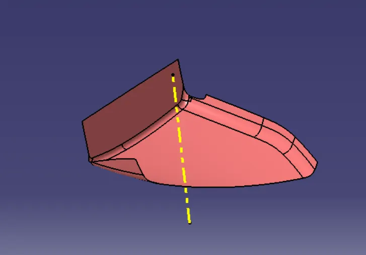
Class B surface:(Bottle Holder)
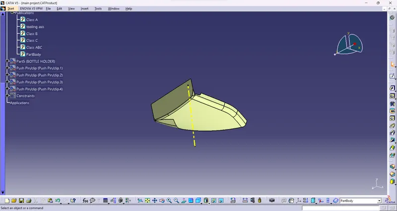
Class C surface:(Bottle Holder)
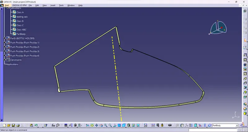
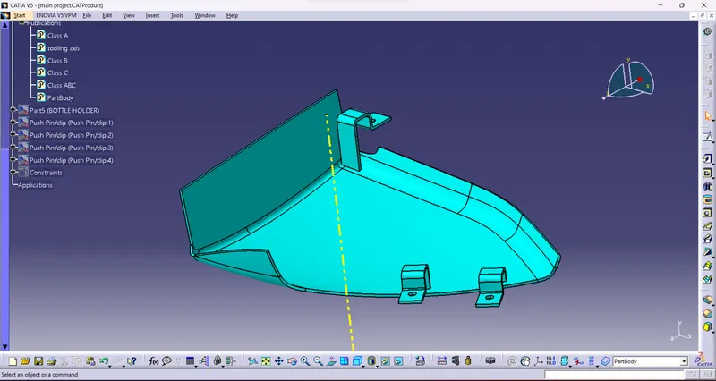
Class ABC Surface:(Bottle Holder)
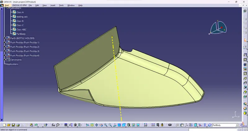
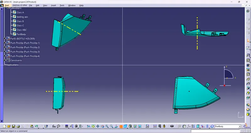
Part Body:(Bottle Holder)
Draft Analysis:(Bottle Holder)
Map Pocket:
Class A Surface:(Map Pocket)
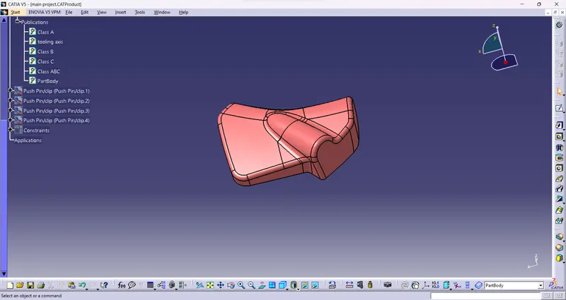
Tooling Axis:(Map Pocket)
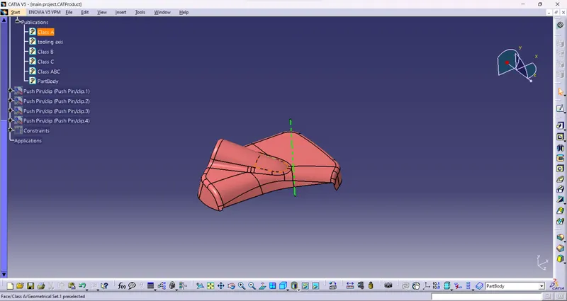
class B Surface:(Map Pocket)
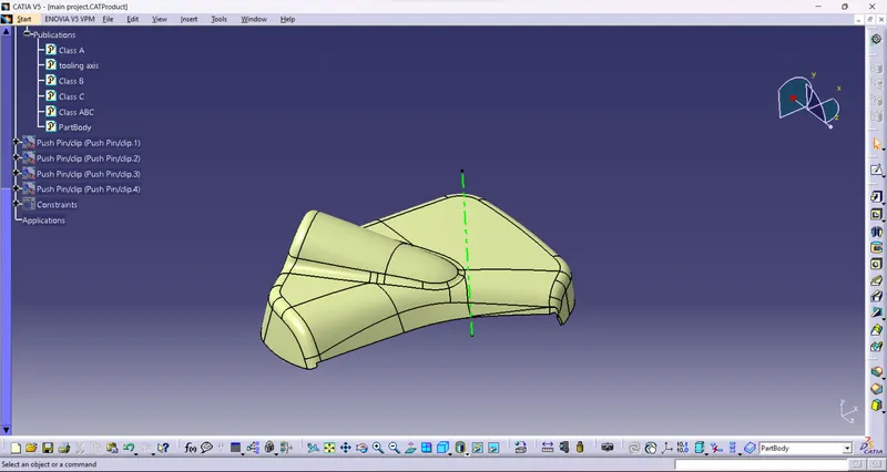
Class C Surface:(Map Pocket)
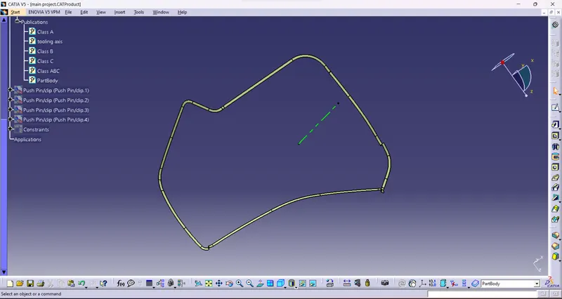
Class ABC Surface:(Map Pocket)
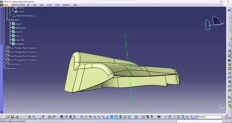
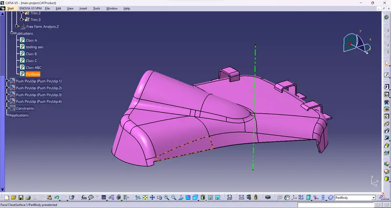
Part Body:(Map Pocket)
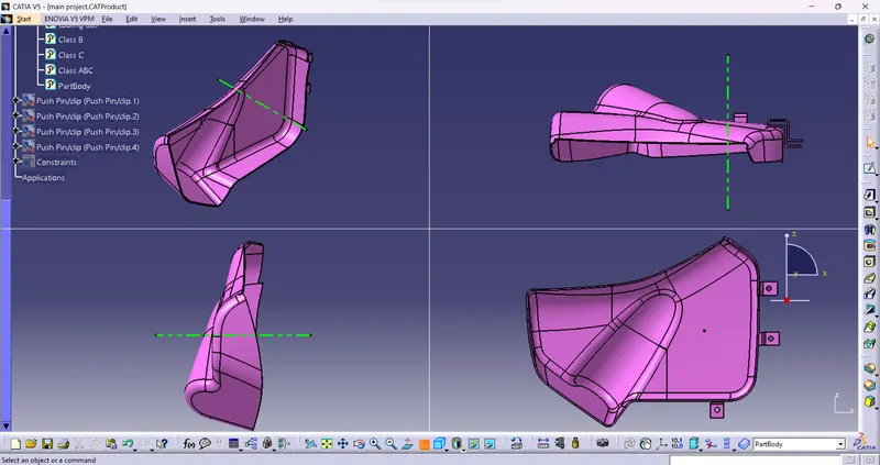
Draft Analysis:(Map Pocket)
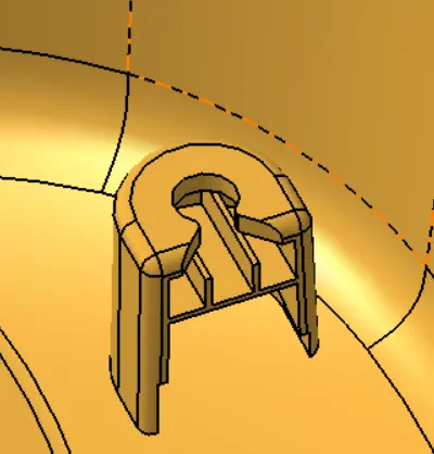
Dog House
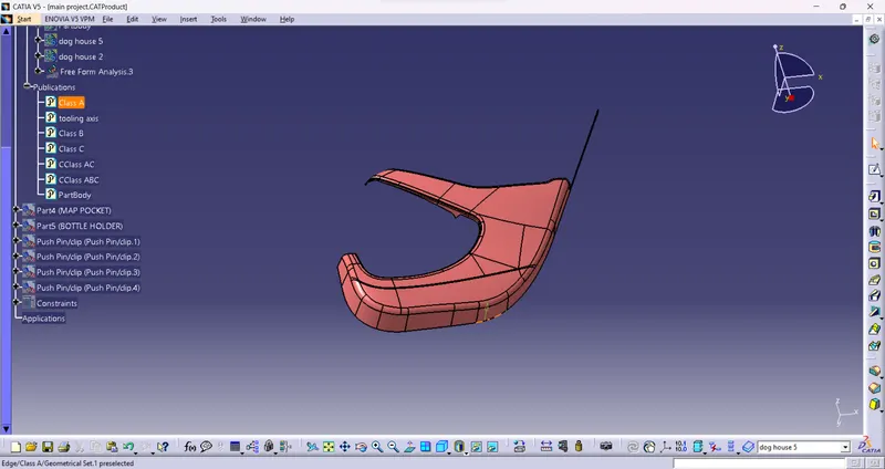
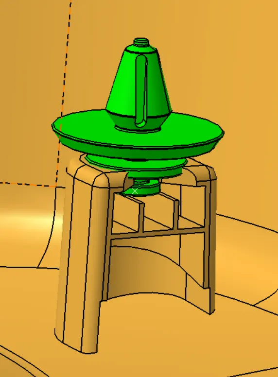
Dog house is an engineering feature used in plastic trim design. These are used as supporting feature and other engineering features such as bosses, locators etc are mounted on them to increase their strength. Dog houses require a slider for moulding and are subjected to draft analysis along the slider axis to prevent breakage during ejection from mould cavity.
Draft Analysis:
PUSH PIN:
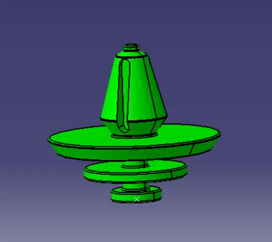
Push Pin are fixing cmponents mount on dog house which help in clipping the part to the other body. As the push Pin are manufactured else where and is not in our zone of concern so we have ignored the rules while making the push Pin and made a general Pin of similar shape in part design without following any rules.
Assembly of Push pin and dog house on lower substrate
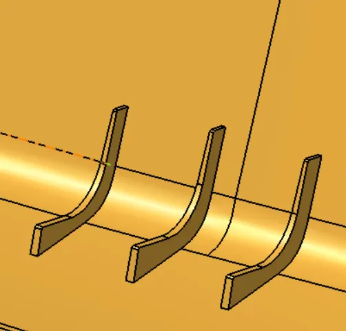
Ribs
Ribs are thin wall-like structures that add support and rigidity to injection moulded parts. They are thinner than primary walls and are used to support these walls, as well as bosses, by running perpendicular to these structures. Ribs are often used to replace thick wall sections to avoid sink marks, warp, and voids.
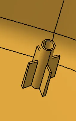
Heat Staking using heat stakes
Heat staking technology is quite simple in concept. Whenever two or more components need to be attached to one another, and at least one is made of a thermoplastic, a combination of heat and pressure can be used to reform the plastic to the many shapes or profiles to retain or join the parts together.
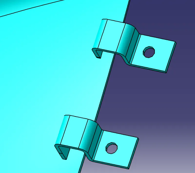
Flange:
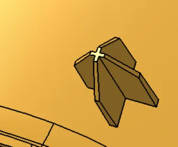
Locators:
Locators are the small projections place on a plastic part which helps in the proper alignment and arresting of the components for fixation. There shall be a hole in the mating part so as the locator slides inside and fits in properly with the other part
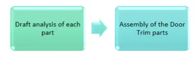
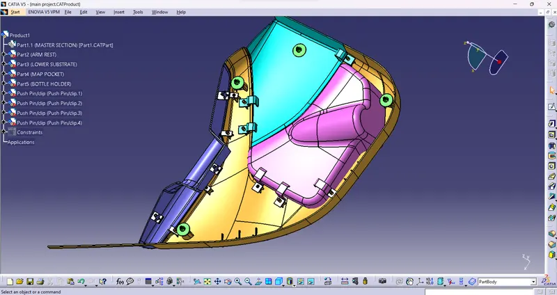
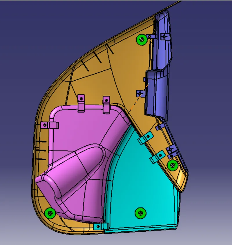
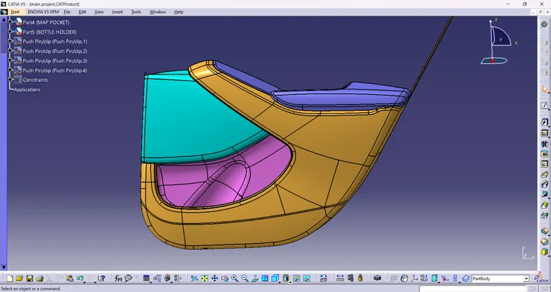
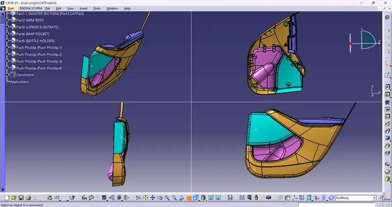
ASSEMBLY OF ALL PARTS:
CONCLUSION:
The door trim was successfully created with all the design rules taken into considerations for feature attachment and the main part was created using the master section provided with the input class A.