Door Trim Lower with Engineering Features
Door Trim Lower with Engineering Features
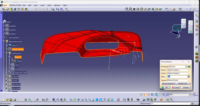
Tooling Axis:
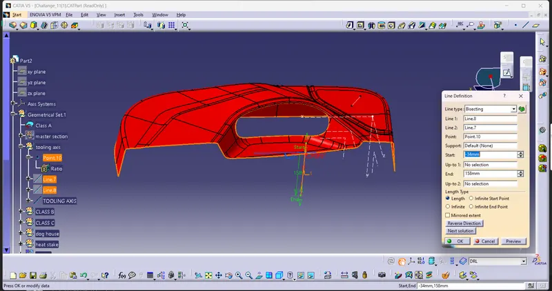
Create a point (Coordinates) 0,0,0 mm and Create a Line - NormalTo Surface click on the point and take a surface (zx plane), give some color and make it a dashed line.
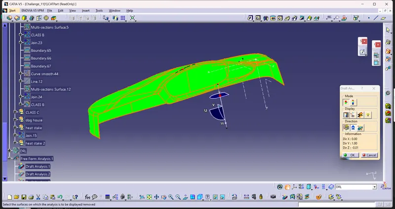
Take a draft analysis with A surface in positive green and blue, little deviation is there.
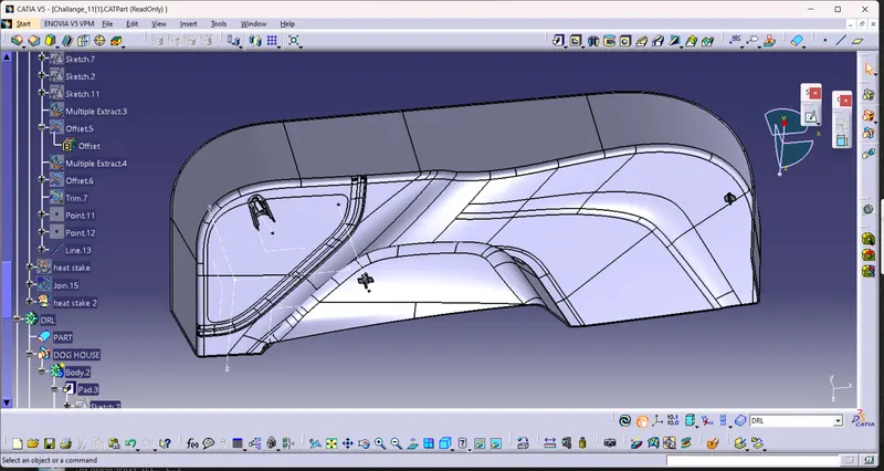
And same thing to do in final draft analysis with final solid component, it seems a deviation green and blue that’s fine acceptable.
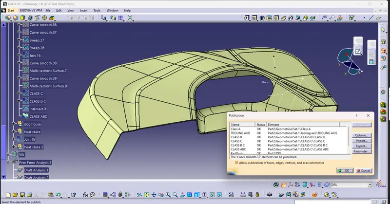
And Publicate the Tooling Axis.
DRAFT ANALYSIS
The Draft Analysis command enables you to detect if the part you drafted will be easily removed. This type of analysis is performed based on color ranges identifying zones on the analyzed element where the deviation from the draft direction at any point, corresponds to specified values.
Before going to drat analysis go to customized view parameter >under mesh >check material and then click ok.
Now for draft analyses go to insert » analysis » feature draft analysis.
Use the compasss to define the draft direction.
In the colour scale change the draft angle to 3 degree.
The component changes to green in indication of passing draft angle.
Use running point to check the angle on the component.
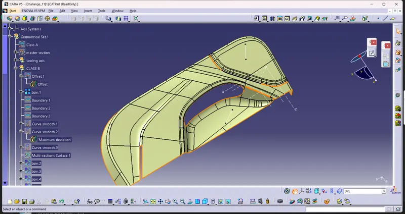
CLASS B SURFACE
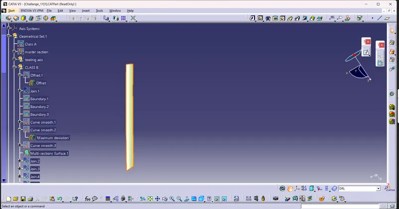
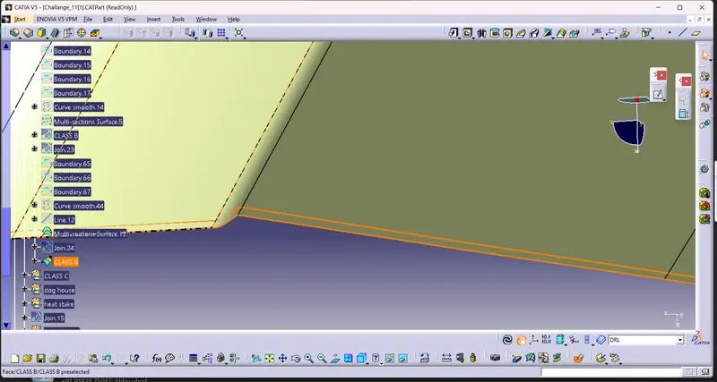
Class-B surface means the thickness of a part it is not visible and is inside part. In other words, the Class-B surface is a surface below a certain thickness from the class-A surface. This is the surface that contains engineering aspects of a model.The Class B finish is a quality finish with only minimal imperfections.
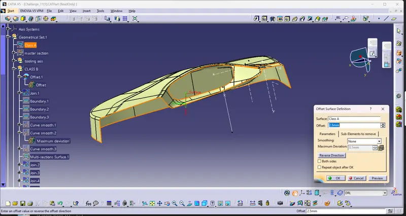
A Class B finish is the most common finish for exterior surfaces. It is normally specified on surfaces such as external covers, panels, and parts that are fairly prominent.patches are created while offsetting the surface. Rework on the patches using the features like extract, multi-extract, sweep, multi-section surfaces, extrapolate.
CLASS C SURFACE
The surface that joins class-A and class-B surfaces are class-C surfaces.
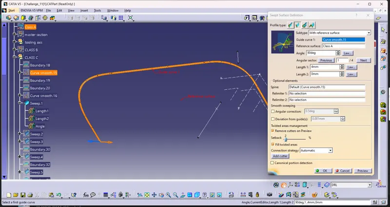
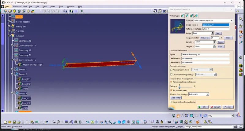
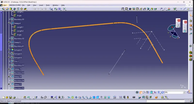
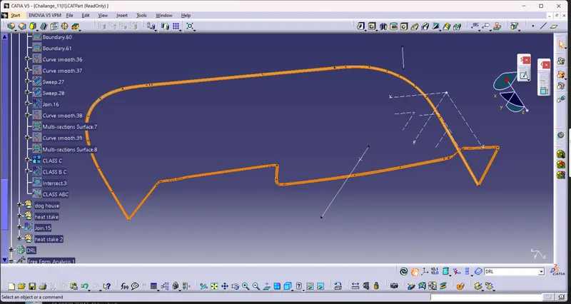
Class C is often specified for interior surfaces not readily visible, surfaces that will be covered by another part when assembledThe Class C finish allows more imperfections than Class A or B. Class C is often specified for interior surfaces not readily visible, surfaces that will be covered by another part when assembled, or surfaces which the Customer feels do not need to meet a high cosmetic finish.
class ABC
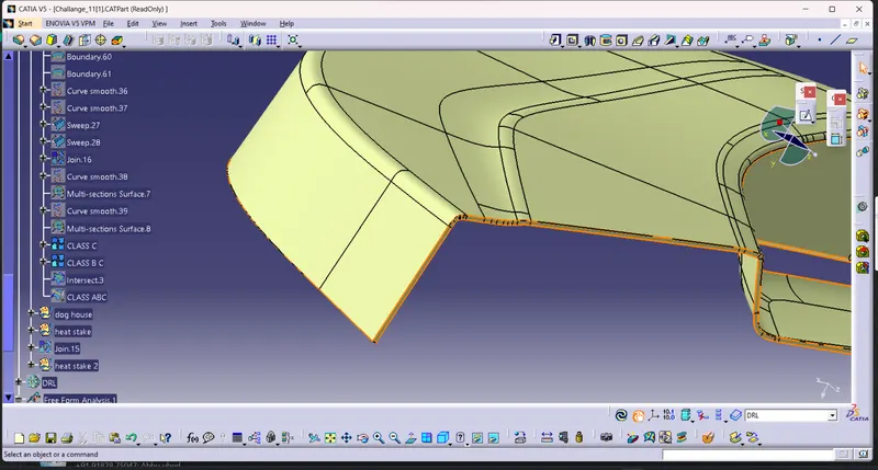
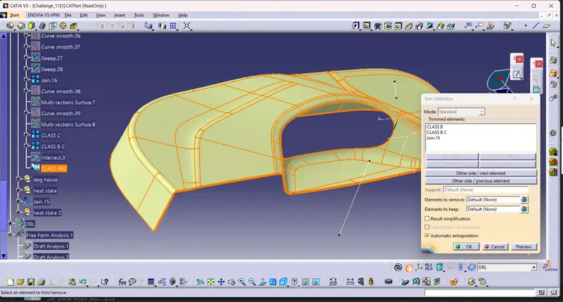
solid analysis
The Draft Analysis command enables you to detect if the part you drafted will be easily removed. This type of analysis is performed based on color ranges identifying zones on the analyzed element where the deviation from the draft direction at any point, corresponds to specified values.
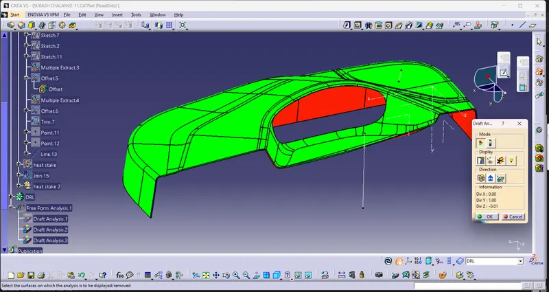
Before going to drat analysis go to customized view parameter >under mesh >check material and then click ok.
Now for draft analyses go to insert » analysis » feature draft analysis.
Use the compasss to define the draft direction.
In the colour scale change the draft angle to 3 degree.
The component changes to green in indication of passing draft angle.
Use running point to check the angle on the component
Dog house
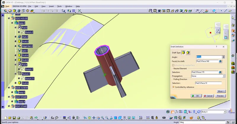
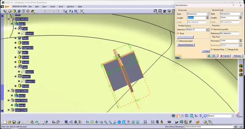
first select the positioning sketch and create the one profile of the dog house and do pad for the profile
then create draft at outside and inside of the body with 3degree
and draft angle should be the 0.25 degrees
then use the trim option and remove the extra surface
after creating the dog house the do solid analysis for the closed surface
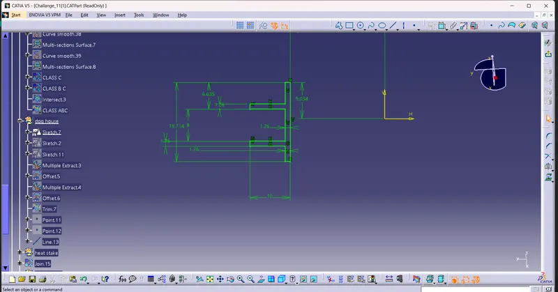
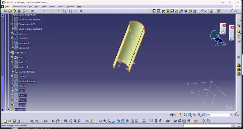
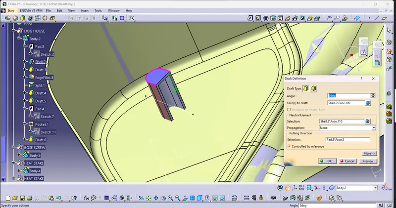
draft analysis
first select the material mode and click on draft analysis then rearrange the axis to the tooling axis
heat stakes
first select the positioning sketch and create the one profile of the dog house and do pad for the profile
then create draft at outside and inside of the body with 3degree
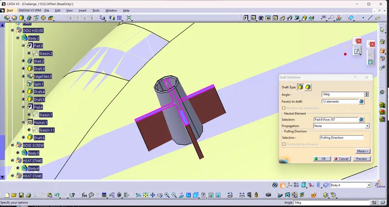
and draft angle should be the 0.25 degrees
then use the trim option and remove the extra surface
after creating the dog house the do solid analysis for the closed surface