Design of backdoor
OBJECTIVES:
- Use the provided styling surface to come up with a back door design, use appropriate design methodologies and provide the necessary reinforcements and embosses.
- Develop a detailed report for the Back door design by explaining the design methodologies and about the components developed in the design
- Perform Draft Analysis along the tooling direction and include the snapshot in the report
INTRODUCTION:
Back Door:
The back door of a car is the vehicle's main storage or cargo compartment, often a hatch at the rear of the vehicle. It is also called a tailgate.
These doors can be operated manually or electric powered. In most of the luxury cars door is electrically operated.
To give the space more flexibility, many cars have foldable rear seats, which can increase the size of the boot space when needed.
TYPES OF THE BACK DOORS:
- TOP MOUNTED
- SIDE MOUNTED
- BOTTOM MOUNTED
TOP MOUNTED DOOR
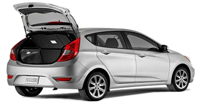
Fig 1: Top mounted door vehicle
Top mounted door refer to smaller cars with a boot lid that incorporates the rear window and is hinged at the top. Ford Focus, or a Volkswagen Golf is the example of the top mounted cars.
Side mounted car:
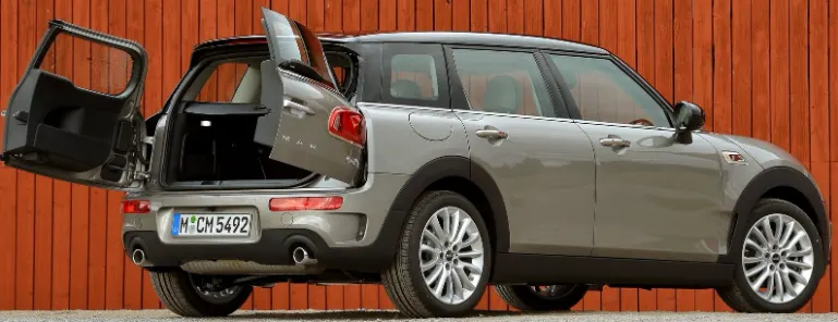
Fig 2: Side mounted door vehicle
Side-mounted doors are the one which is used in the van type MPVs, SUVs, pickup truck vehicles. These side-mounted doors or barn doors are a lot easier compared to top-mounted doors.
TYPES BASED ON OPENING MECHANISM:
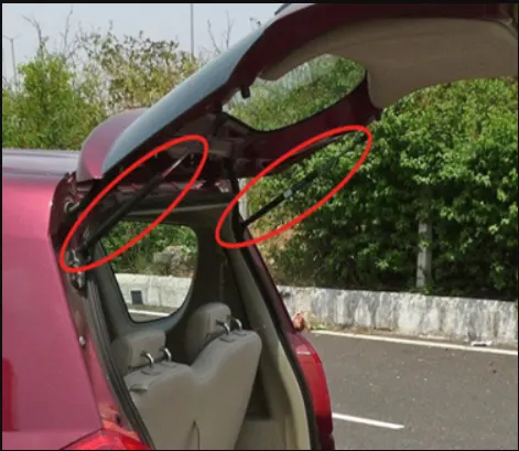
Fig 3: Gas stay
Gas stay type backdoor is an ideal and most commonly used tailgate mechanism from lower segment car to luxury car segment.
POWER LIFT MECHANISM:
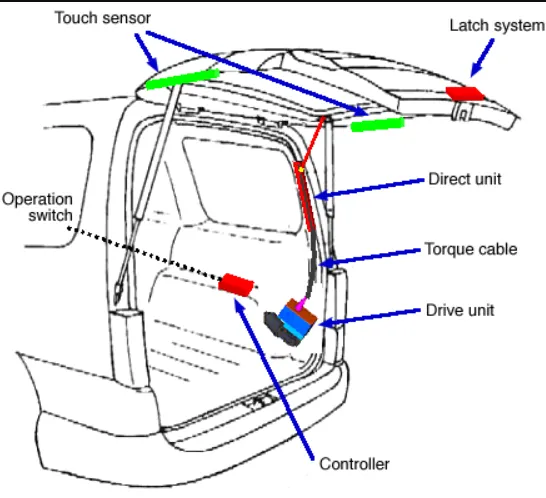
Fig 4: Power lift mechanism
Vehicle liftgates are operated by a variety of power actuators. The most typical systems are electrically powered with a computer control system executing driver’s command to open and close the liftgate. The control system has to have enough power to open and close the liftgate in specified time over the range of environmental condition. A torque cable is employed to allow a high degree of freedom for drive unit layout. The actuator can be built into the trim. The compact design achieves a smart looking appearance. Manual operation force with low resistance. Safety is maintained when an object is caught in the door.
MANUFACTURING TECHNIQUES:
Selection of material is the first step in manufacturing of door. Studies by different researches show that the efficient design and increase use of composite materials into the automotive parts directly influences the car safety, weight reduction because the efficient design can absorb more deformation and high specific strength and high specific stiffness. Door should have the ability to absorb as much deformational energy as much as possible without breaking. Normally steel is used but steel increases significant weight of the car.
The automotive door is manufactured through various processes like blanking, rolling, forging, stamping and assembly. A door is made by assembling together the inner panel, the outer panel, the inner and outer belt reinforcements, the crash bar and the hinge pillar.
Steel doors are first formed by stamping the inner and outer panel and various reinforcements which differ with the specific door design. Two general types of doors exist from the level of stamping.
- Full frame doors having internal header section. (Popular-view is good + styling)
- Half frame doors not having internal header section.
The number of stamping operation vary according to the draw ratio and the complexity of the openings and apertures on the panel. The range is from less than four passes to more than seven for a major body panel. Typically door inners required a reverse draw. Transfer stamping press or Tandem press are used for this operations. The degree of automation depends on the types of presses and the age of the line. The main benefits of the transfer press are the reduction in labor due to the internal part transfer and the increased stroke rate. There is also a cost advantage to transfer presses in that a single transfer press which can run multiple stations will cost less than an equivalent number of presses in a tandem line.
BACK DOOR DESIGN:
Back door has the following components,
- INNER PANEL
- OUTER PANEL
- HINGE REINFORCEMENTS
- GAS STAY REINFORCEMENTS
- WIPER MOTOR REINFORCEMENT
- LATCH/STRIKER REINFORCEMENT
Given class A surface:
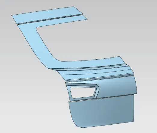
Fig 5: Given Class A surface
The above class A surfaces have an disjoints in few regions, so the class A surface has been repaired.
Repaired Class A surface:
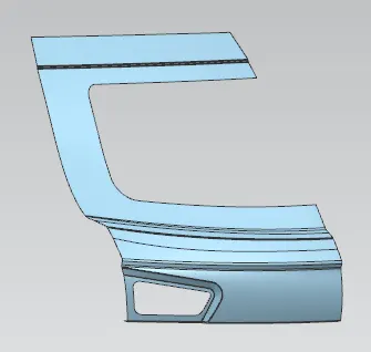
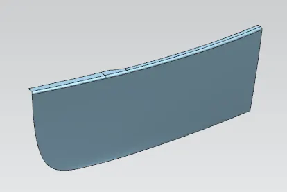
Fig 6: Repaired class A upper Fig 7: Repaired class A lower
TOOLING DIRECTION CREATION:
- create a sketch and draw two lines with respect to the surfaces
- And create a bisecting line with respect to two lines.
- This is our tooling axis.
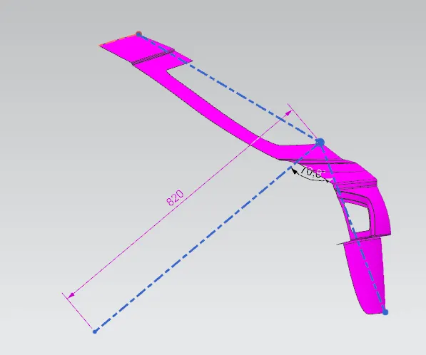
Fig 8: Tooling axis
INNER PANEL CREATION:
Inner panel is the component which is used to strengthening the door assembly and it is the important components which all accessories like hinges, glass guide channel and gas stay are fitted in it. Inner panel is mounted with the outer panel with the help of hemming process.
- Most commonly used material in the Inner panels are steels. Aluminum is used in higher end vehicle to reducing weight of the component. Aluminium is costlier than steel, so it is not used in low budget cars.
After creating tooling axis create a sealing flange by offsetting the class a surface for desired distances
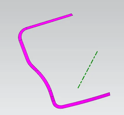
Fig 9: Sealing flange
Then create connecting flanges and joined this with inner panel.
After joining the connecting flanges, create wind shield flange for creating embosses.
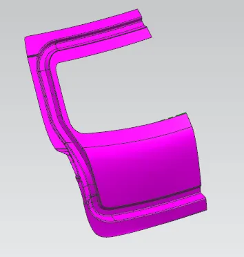
Fig 10: wind shield flange
- After creating windshield flange creating inner panel to outer panel mastic joint flange.
- Then create v type embosses for strengthening the part.
- Then create an another embosses for tail light cabeling process.
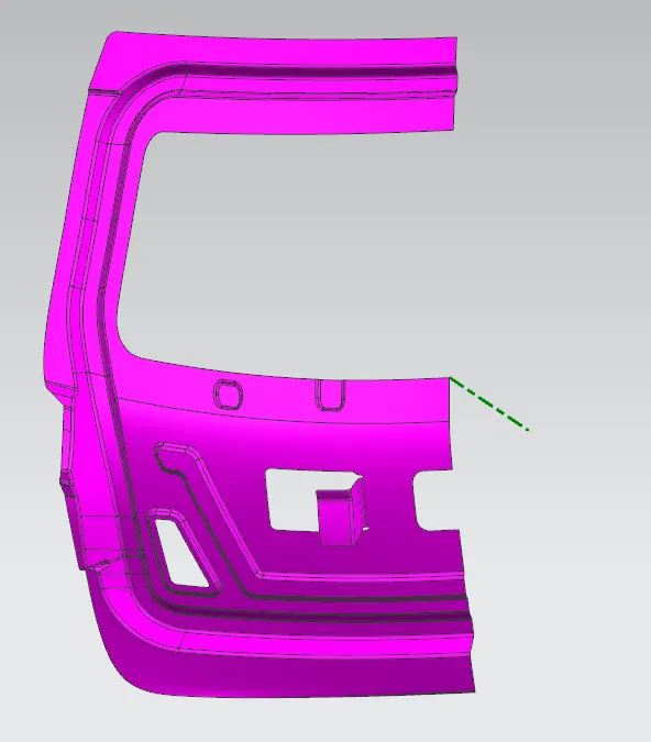
Fig 11: Inner panel mastic point and embosses
After creating the embosses create the hinge mounting of the back door.
- For making hinge mounting we have to create datum plane with respect to the line of the sealing flange.
- Then create a sketch with respect to datum plane and creat one line.
- Then use law extention option to create the flat surface and trim and extend option to create the hinge mountings.
- After that crearte the mounting holes on the surface. This is our hinge moutings
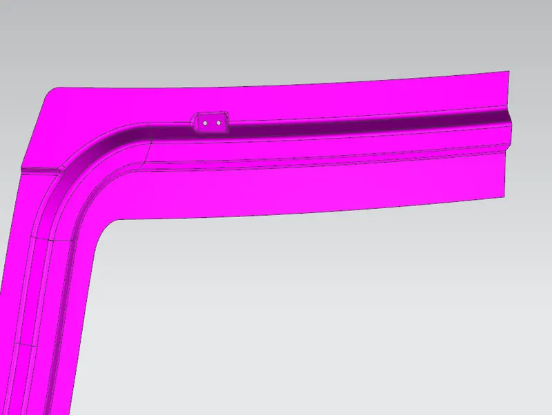
Fig 12: Hinge mounting
After creating hinge mounting we have to create gas stay mountings.
- Following steps as per hinge mounting method, but the location is different.
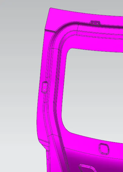
Fig 13: Gas stay mounting
After creating the gas stay mounting we have to mirror geometry the part and joined together for creating wiper motor mounting and latch/striker mounting.
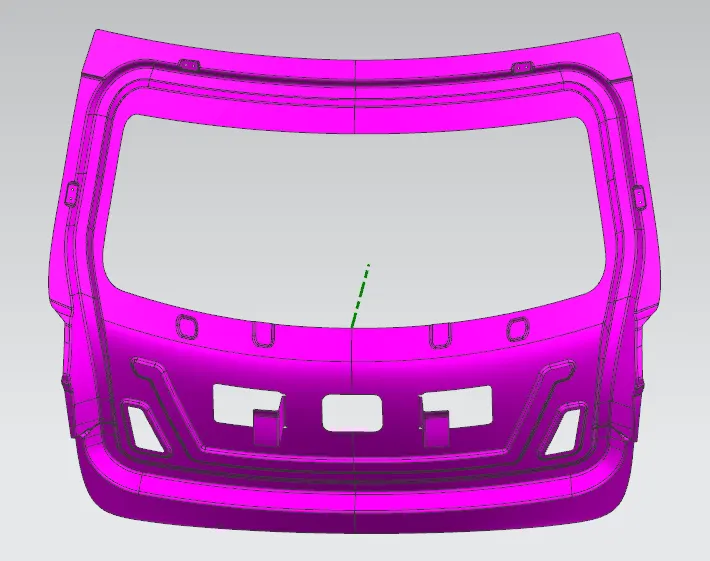
Fig 14: Inner panel mirror geometry part
After that we have to create latch and striker mounting
- For creating latch and striker mounting we have to create sketch for latch/striker tregectory from hinge axis line.
- After creating the sketch point the location and create a line on the same sketch.
- Use law extention option to create a flat surface.
- Then create another flanges from the side and use trim and extend option to create a latch/striker mounting.
- Then put a mounting hole on it.
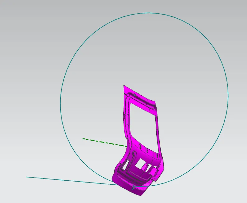
Fig 15: Latch/striker tregectory
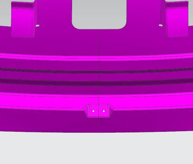
Fig 16: Latch/striker mounting
After completing latch/striker mounting then create wiper motor mountings for following steps
- Create a datum plane using curves on point option.
- Then create a sketch using the datum plane and create a mounting drawing.
- Then project the sketch on the surface.
- Then use emboss option to create a mounting for wiper motor and holes.
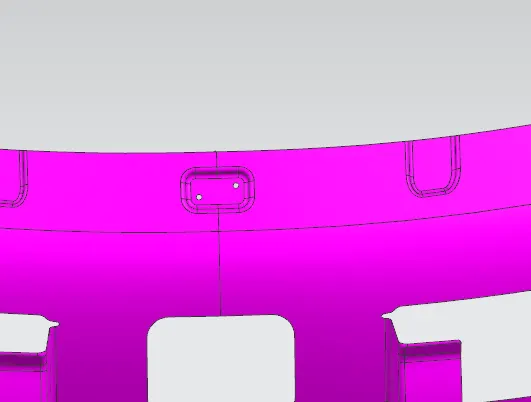
Fig 17: wiper motor mounting
Then thicken the inner panel to 0.75mm
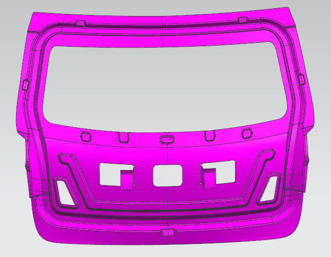
Fig 18: Thickened inner panel 1
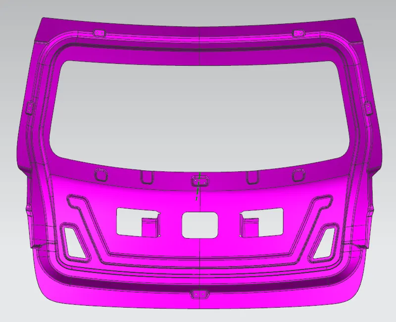
Fig 19: Thickened inner panel 2
REINFORCEMENTS:
After creating the inner panel we have to create the reinforcements for hinge, gas stay, wiper motor and latch/striker. For creating reinforcement we have to use wave geometry linker option to select the appropriate surfaces from inner panel.
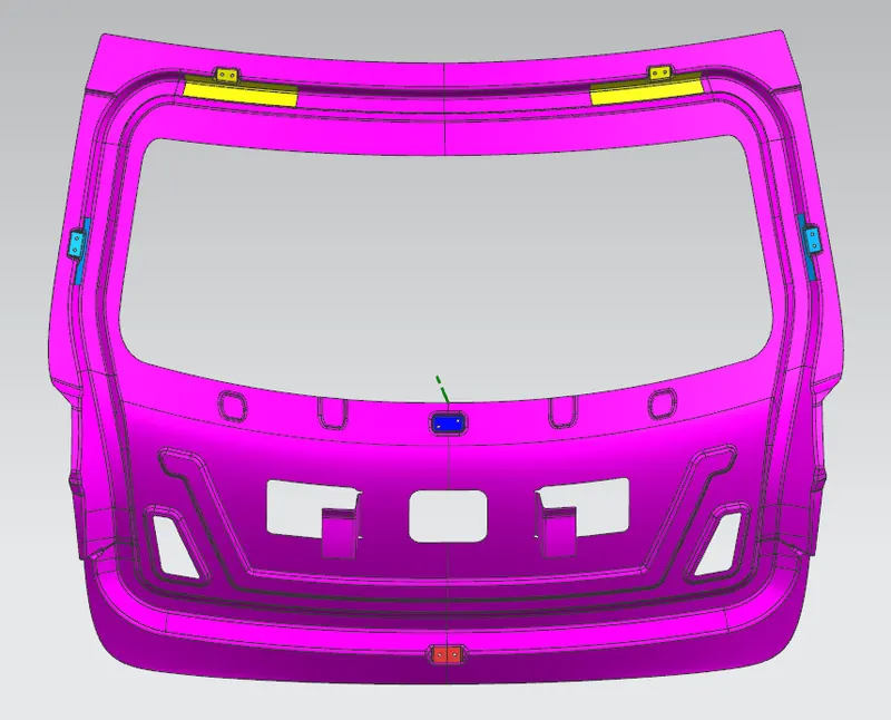
Fig 20: Reinforcements
OUTER PANEL HEMMING:
Hemming is a sheet metal joining process which is widely used for vehicle closures. As the latest hemming process type, the roller hemming process is the latest hemming process used in industries, main advantage of the process is improved product quality. Trial and error method is the general approach to design the process in the industry due to limited know-how in the roller hemming. In the current roller hemming process of the tailgate, three stages including two pre-hemming and one final hemming stages are being applied.
Creation of hemming flange of the outer panel surface:
- Create offset curve on surface of the outer panel from 0.5mm offset
- create law extention of the cuves seperately
- Joined all the law extention together
- Then create offset of outer panel at 2.65mm
- Then using face belnd of three faces option to blend the two surfaces together, we will get the nice hemming flange.
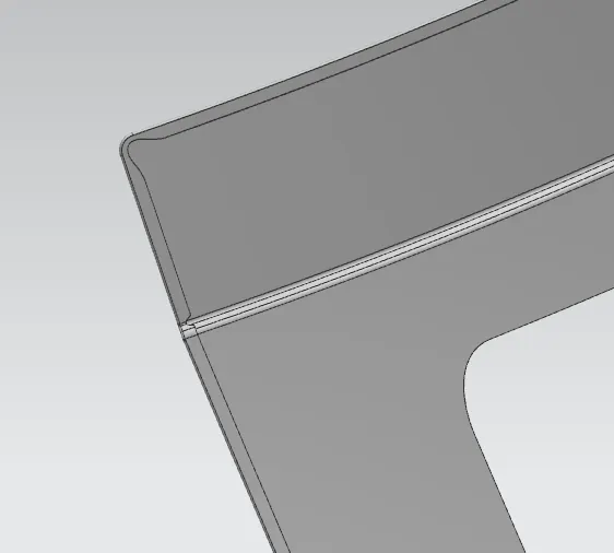
Fig 21: Outer panel upper hemming
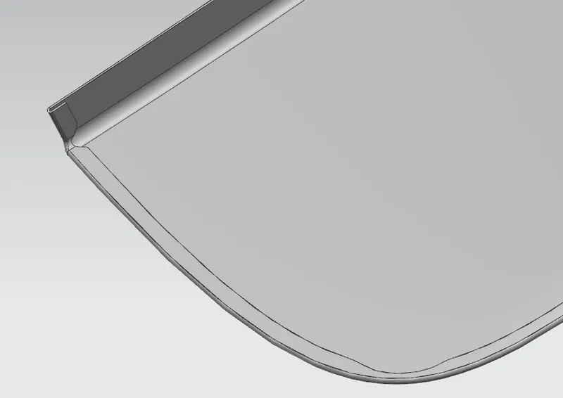
Fig 22: Outer panel lower hemming
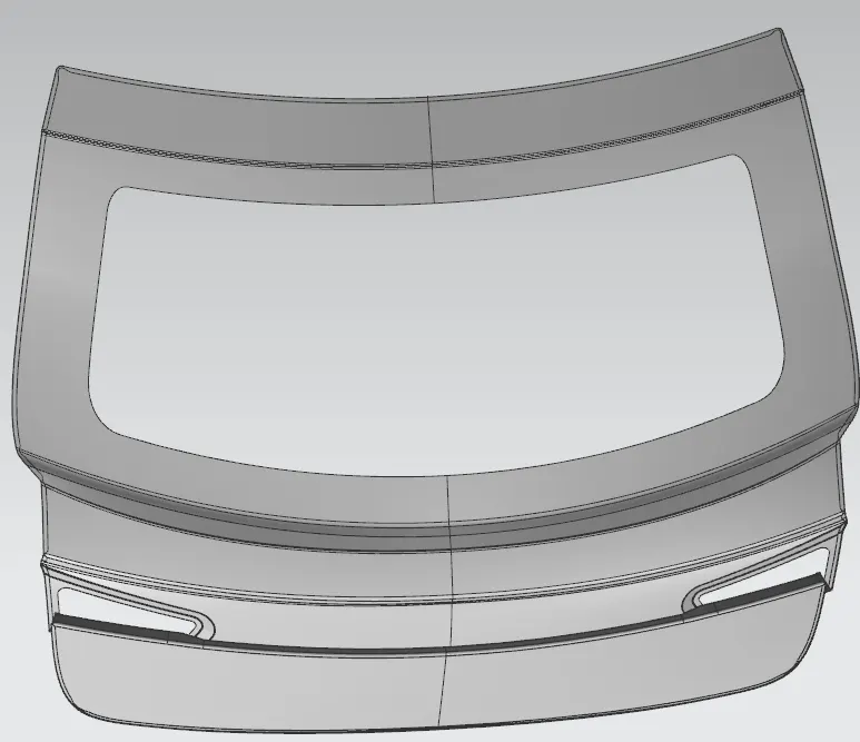
Fig 23: Outer panel upper and lower hemming
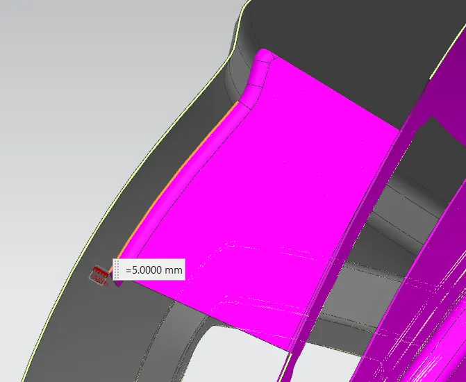
Fig 24: Mastic point gap
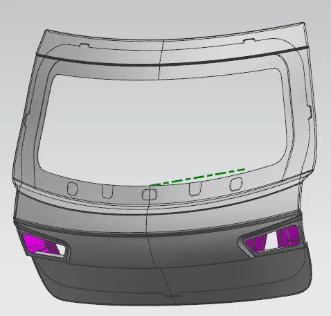
Fig 25: Back door assembly 1
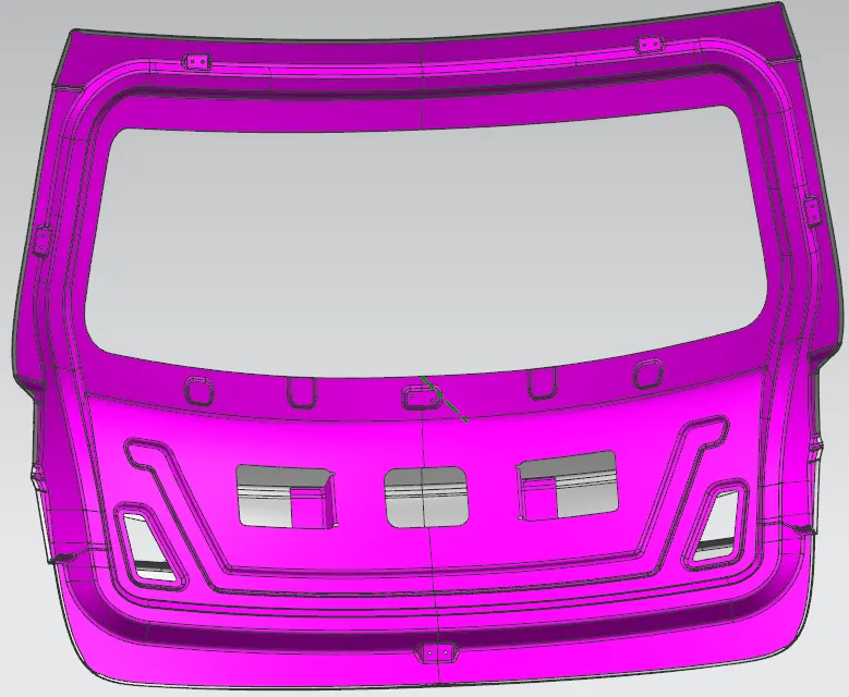
Fig 26: Back door assembly 2
DRAFT ANALYSIS:
For checking draft analysis we have to choose draft analysis option and select the surface and choose tooling axis as a vector, then set the draft angle as 7 degs.
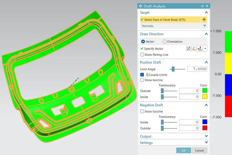
Fig 27: Draft analysis 1
The surfaces were cleared in the draft analysis except below areas.
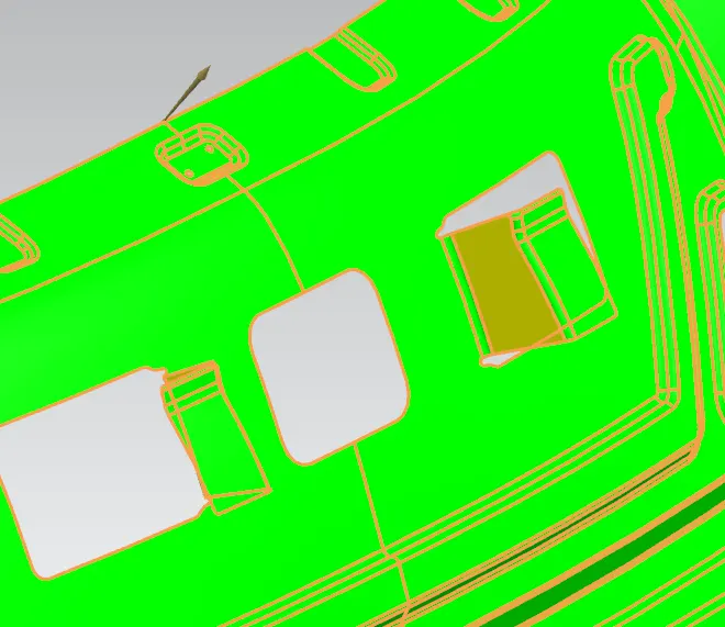
Fig 28: Draft analysis 2
In this area we will doing bending operation, so there is no need for drawing ing portion.
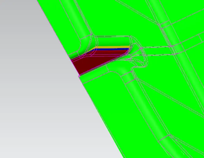
Fig 29: Draft analysis 3
We can choose seperate tooling axis for this portion to clear the draw operation.
CONCLUSION:
From the provided styling surface of a back door design, I used appropriate design methodologies and provided the necessary reinforcements and embosses in the BackDoor design.