Design of backdoor
Aim:
The main aim is to design the Back door of a car from scratch following the design parameters using CATIA V5.
Theory:
Back Door:
The back door is placed at the rear end of a car at which the loads can be kept. It is also called a trunk or tailgate. It consists of an outer panel, inner panel, and some reinforcements to give strength to the component. Trunk lids are made of steel which is stamped using the deep drawing process. The thickness ranges from 0.6- 0.8mm for the panels.
Reinforcements size- 1-1.5 mm

Components to create:
- Outer Upper panel
- Outer Inner Panel
- Inner Panel
- Hinge Reinforcements (LH and RH)
- Gas Stay Reinforcements (LH and Rh)
- Latch Reinforcement
Procedure:
- Checking the Geometry:
- Once the model is opened, we get a Class A Surface of the back door.
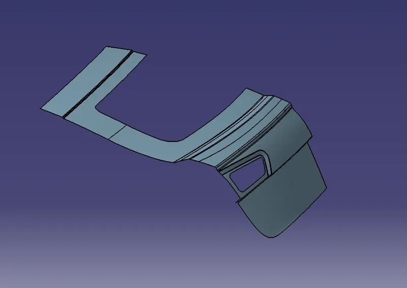
- Try joining the Upper surface of the car, if the surface joins we get the outer surface and if the surface didn’t join then we need to create the surface by using Multi-section surfaces.
- Create the fillet areas, Tail Lamp area as those areas will be vulnerable and are unable to join together.
- Creating the Tooling Axis:
- Click on the line option and select the Bisecting option.
- Now, Right Click on the 1stLine option to create a line. Select the point from the Vertex of the Upperside of the corner to the position where the declination starts. Click ok and the line is created.
- Now, click on the Second Line and follow the same procedure but from the lower surface. Click Ok and the line is created.
- After clicking ok, the bisecting line is created.
- You can also use a Point and direction method to create a tooling axis.
- The line created is the main tooling Axis.
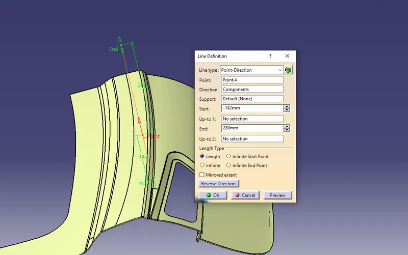
- Creating the Outer Panel Upper Surface:
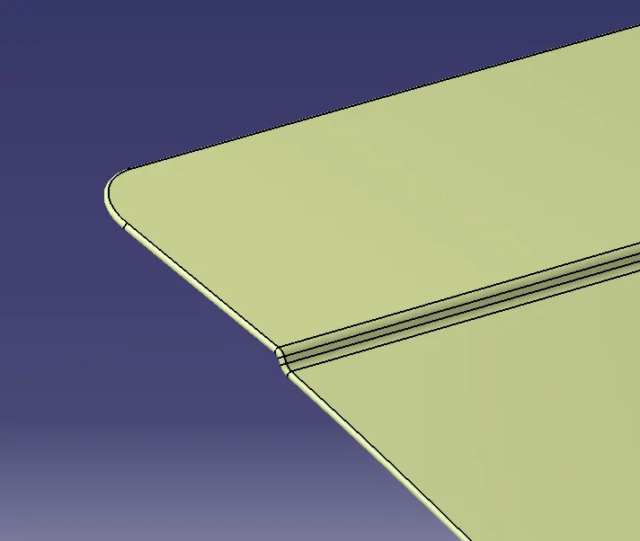
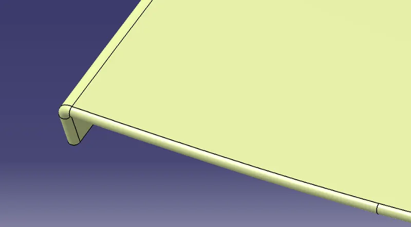
- To create the Upper panel, the areas that are created before need to be joined together. Once those are joined the hemming needs to be done.
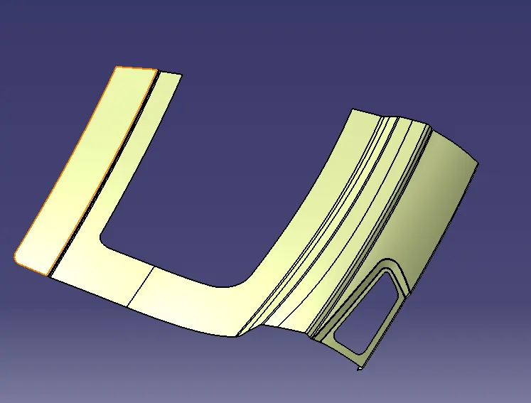
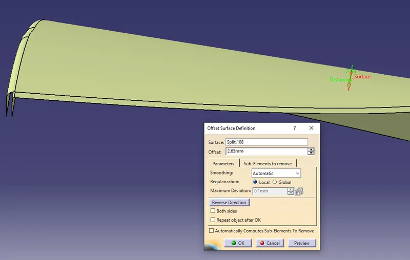
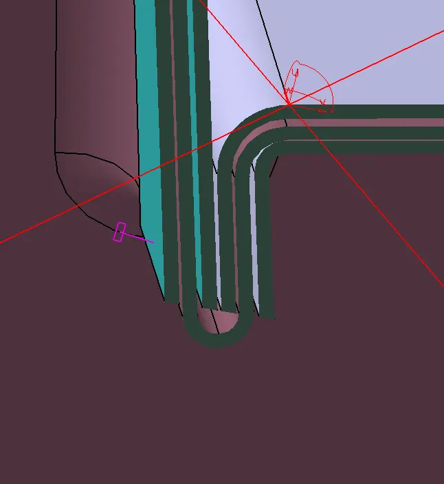
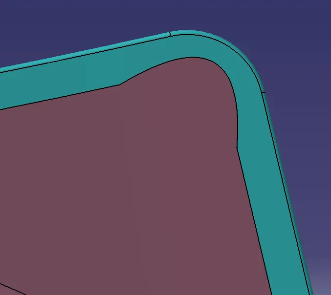
- To perform Hemming, offset the present surface to 2.65mm (Outer Surface Thickness- 0.75mm, Inner panel thickness- 0.75 gap between Outer and Inner panel – 0.2mm, Hemming area bent region- 0.75mm, the gap between hem and Inner panel- 0.2mm)
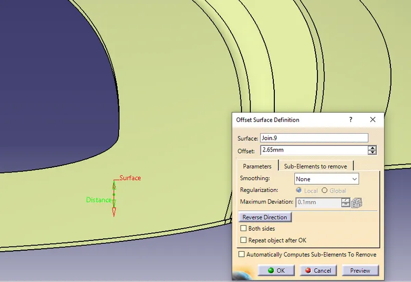
- Use the parallel curve option to 10mm to create the surface.
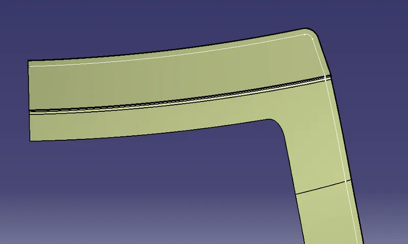
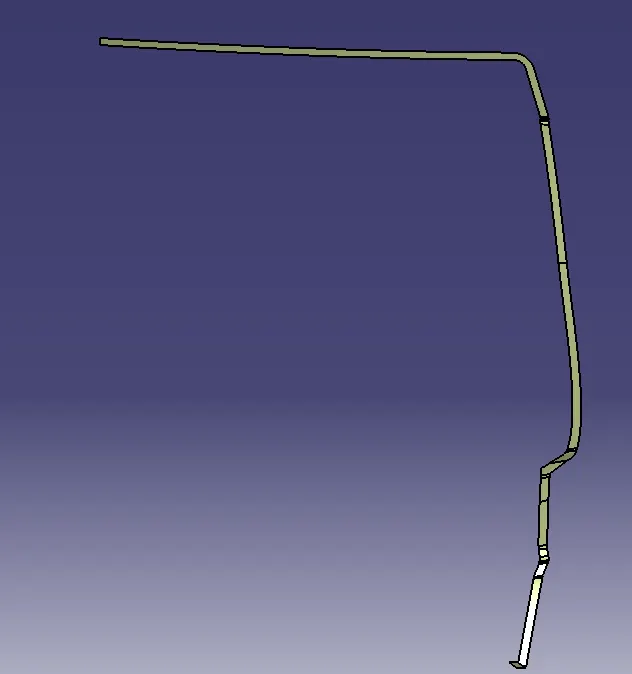
- Use the connect option to create the curved line. We can use the spline option as well.
- Select the points and the support lines with a tangency of 2.
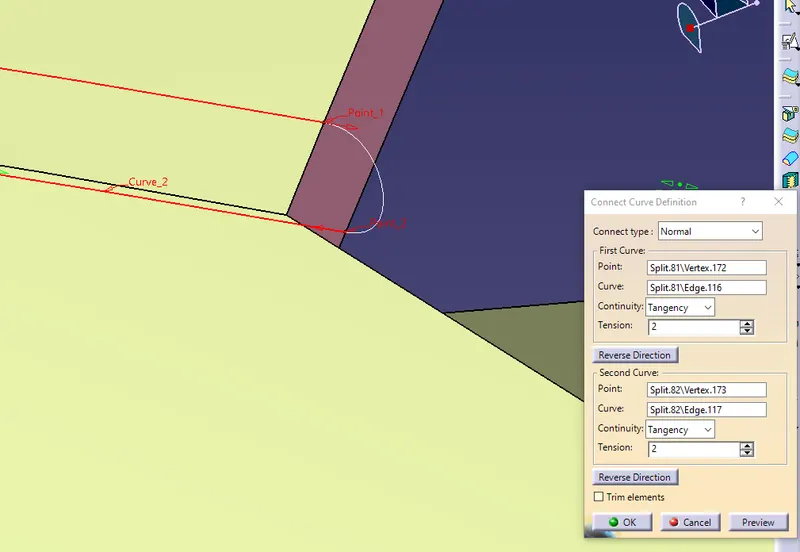
- Use the multi-section surface option to fill the surfaces and join the surfaces.
- Near the corner, areas create the sketch to perform a cut-out of those sections.
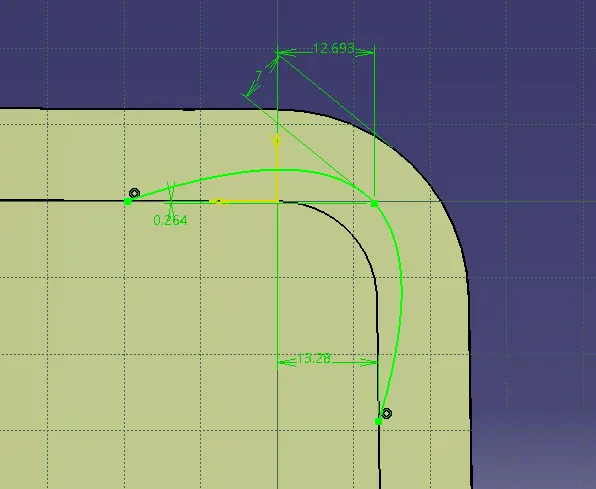
- Creating the Outer Panel Lower Surface:
- To create the Lower panel, extraction of the lower end of the upper part needs to be done.
- Offset it to 0.2mm and extrapolate the lower panel and the 2 surfaces.
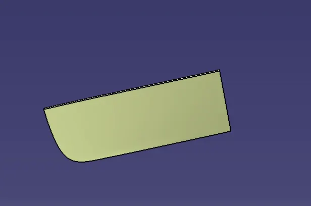
- Now give an edge fillet of 3.5mm. Offset the created surface to 2.65 to perform hemming.
- To perform Hemming, offset the present surface to 2.65mm (Outer Surface Thickness- 0.75mm, Inner panel thickness- 0.75 gap between Outer and Inner panel – 0.2mm, Hemming area bent region- 0.75mm, the gap between hem and Inner panel- 0.2mm)
- Use the parallel curve option to 10mm to create the surface.
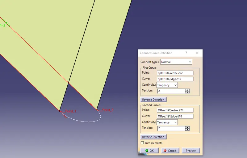
- Use the connect option to create the curved line. We can use the spline option as well.
- Select the points and the support lines with a tangency of 2.
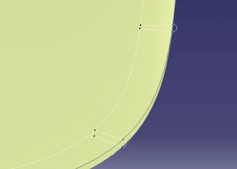
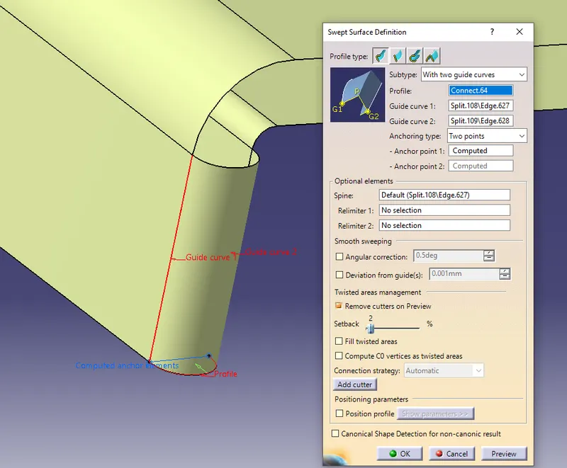
- Use the sweep option to fill the surfaces with the help of two guide curves and join the surfaces.
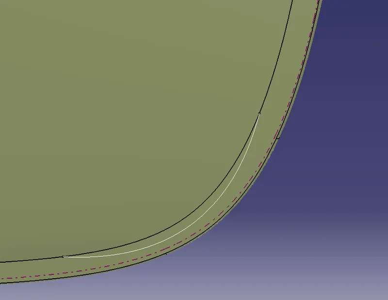
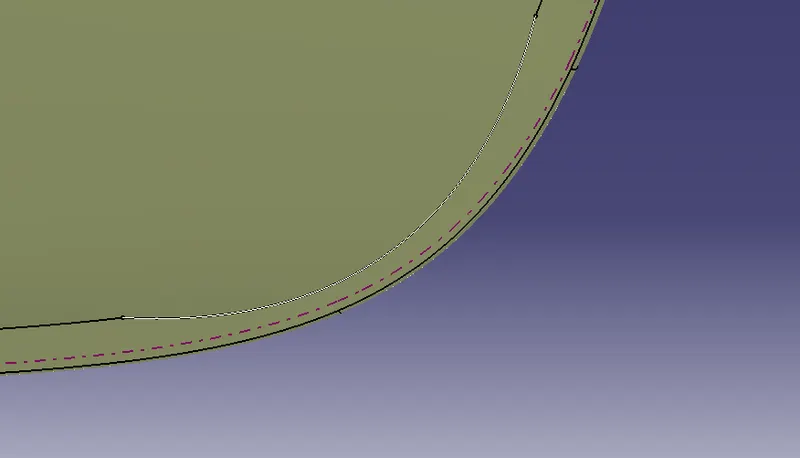
- Near the corner, areas create the sketch to perform a cut-out of those sections.
- Creating the Inner Surface:
- To create the Inner Surface, first, select the upper and lower surface and join them together with the fillet of the 3mm.
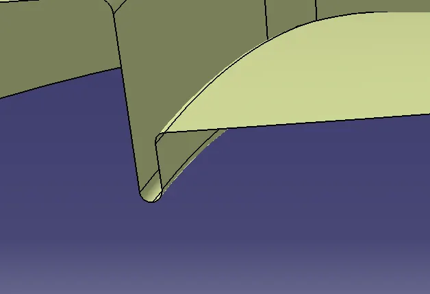
- Now, create the offset of 1.7mm and again offset it to 25mm downwards.
- Use the parallel curve option to cut the elements
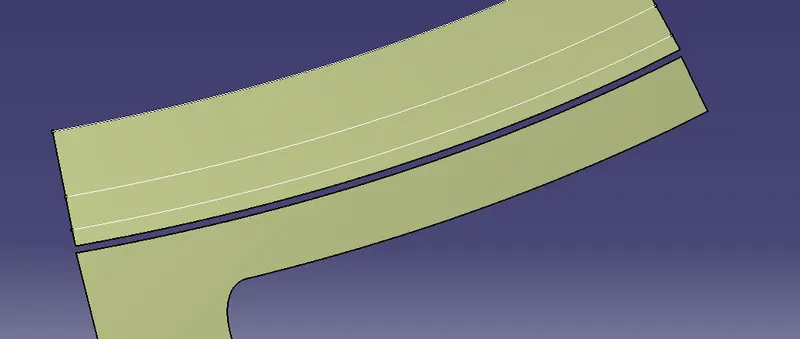
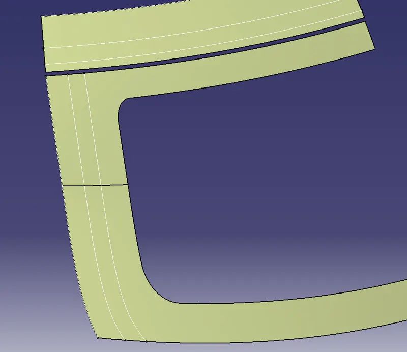
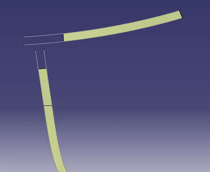
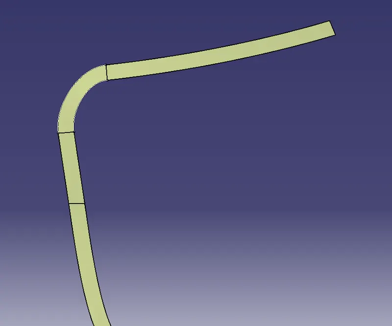
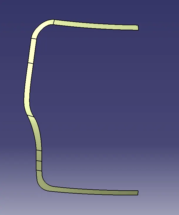
- Use the Sweep option to create a sweep with an angle of 25 degrees with the tooling axis.
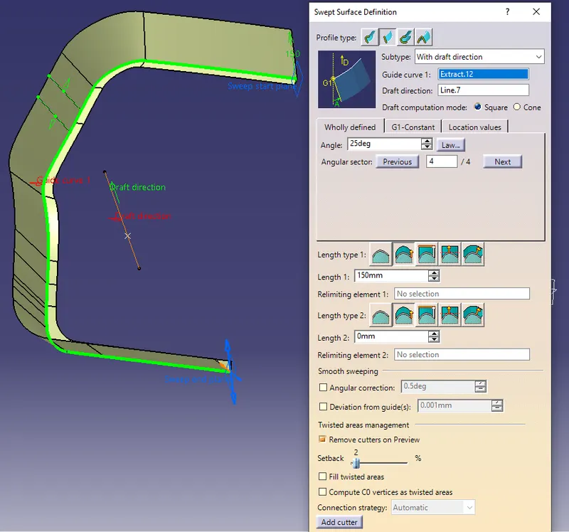
- Now, use the offset of 1.7 to trim the sweep and creating a surface.
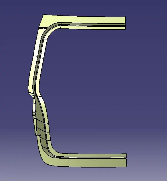
- After creating the boundary surface of the inner surface, extract the windshield area and extract it.
- Now create a sweep inside with an angle of 25 degrees and trim it with windshield extract.
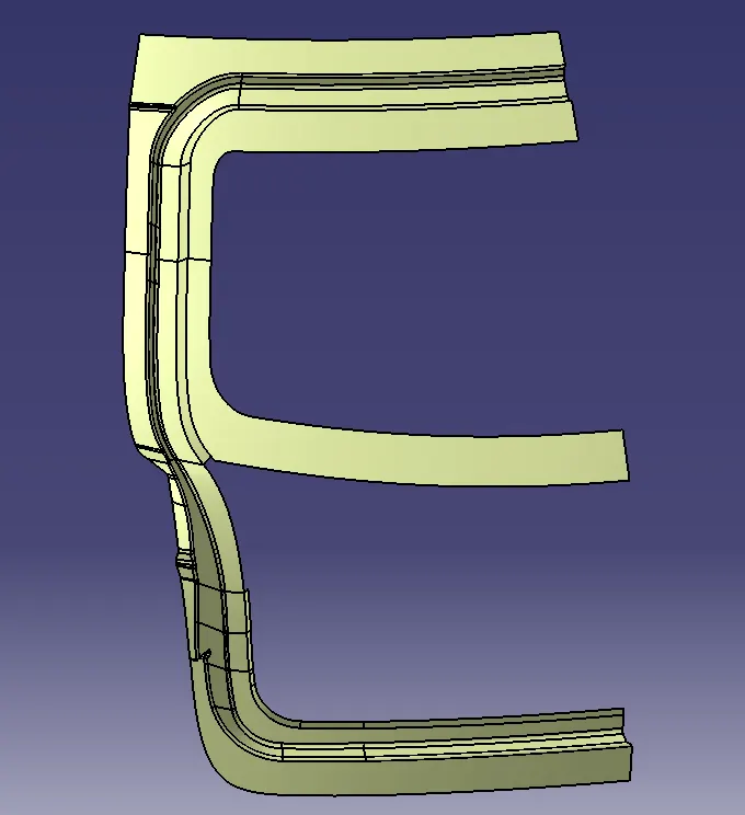
- Similarly, create the lower side surfaces using the connect option and trim them.
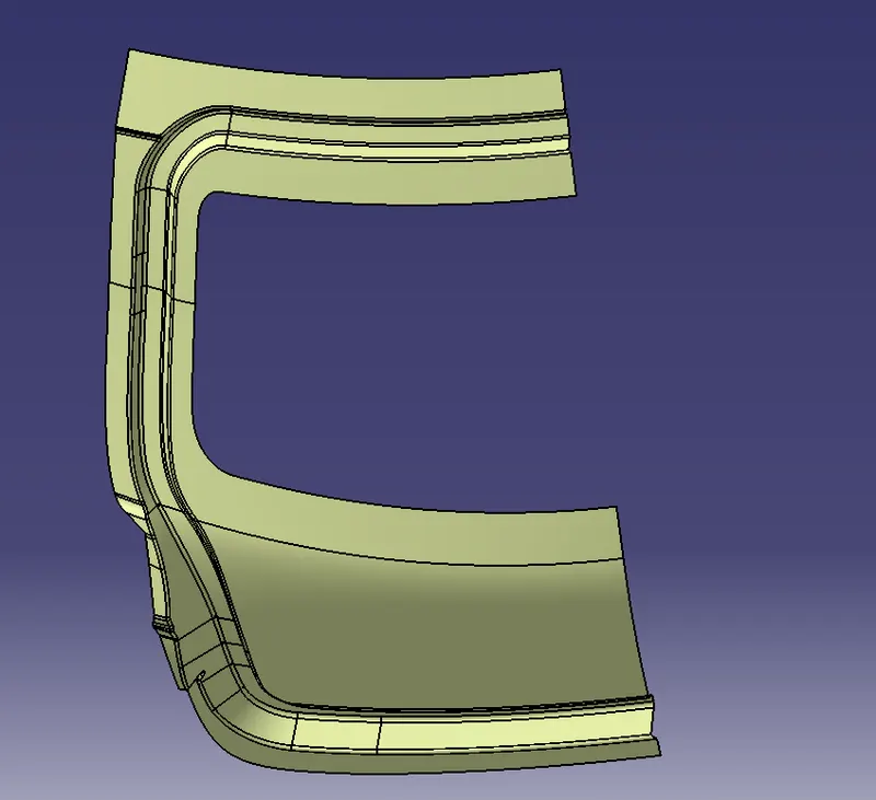
- Give the fillet value of 5mm to the corner surfaces.
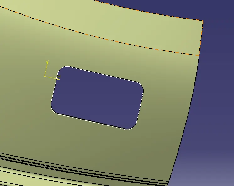
- A mastic point needs to be created. Create a Sketch of rectangular shape and provide a cut out on the surface.
- Now, use the sweep option to create the surface perpendicular to the base surface.
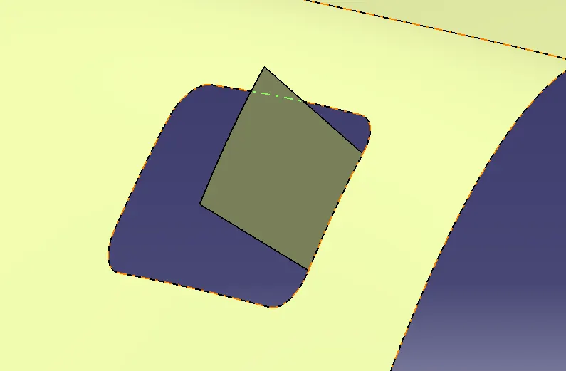
- Offset the main surface to 5mm and trim the surface with the sweep.
- Cut the unnecessary elements and make sure the trimmed outer surface is less than half of the length of the cut out created at the bottom.
- Give the edge fillets of 5mm to the surfaces created.
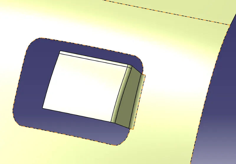
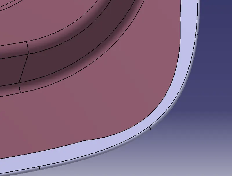
- To give the reliefs to the sweep surface, go to the freestyle workbench and create a spline with points to create the reliefs on both sides.
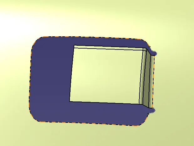
- To give the cut-outs, draw a sketch of the required shape such that when the crash happens the load must be distributed to the above providing safety to the people inside the car.
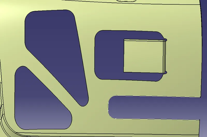
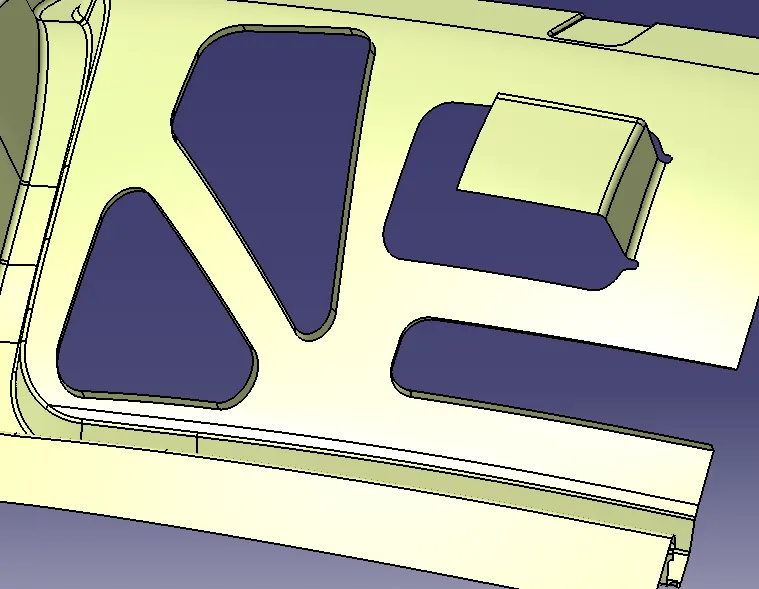
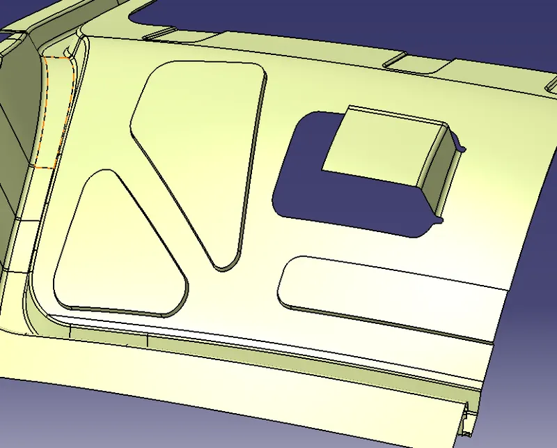
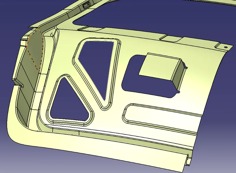
- Follow the same procedure for the embossments at the windshield area as well.
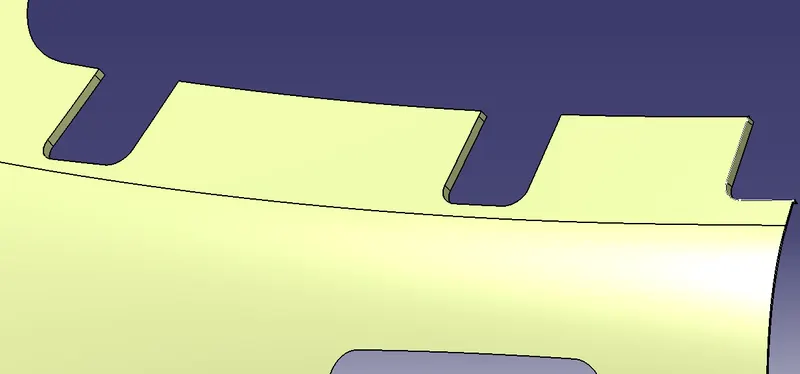
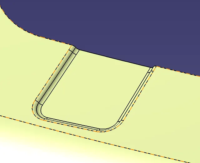
- Making Hinges, Gas Stays, and the Latch part on the Inner Surface:
- The Hinges are created at the top of the inner panel using the parallel curves and corner option.
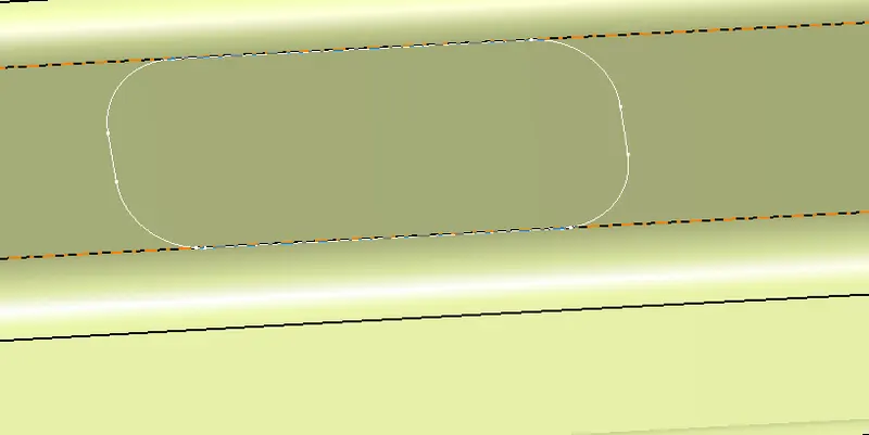
- Use the split option to cut the elements and perform a sweep with an angle of 10 degrees.
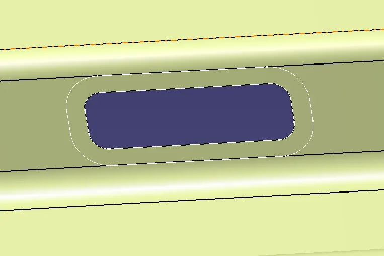
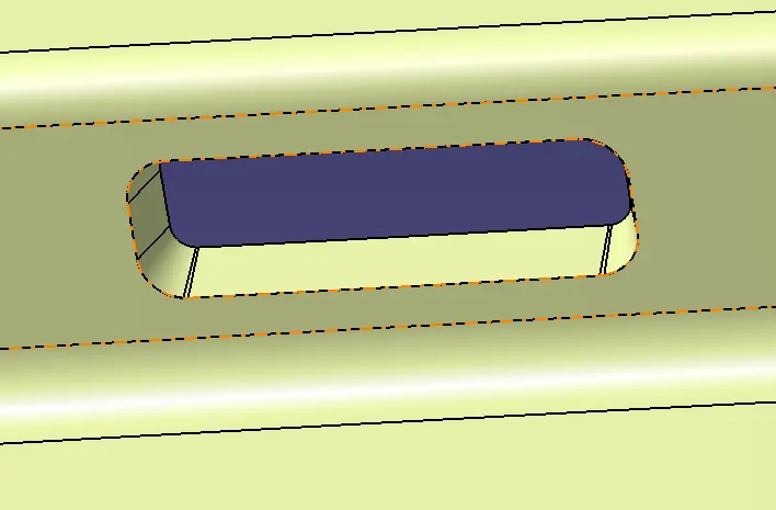
- Offset the surface to 4mm and trim it with the sweep surface. Give the fillets of 4mm to it.
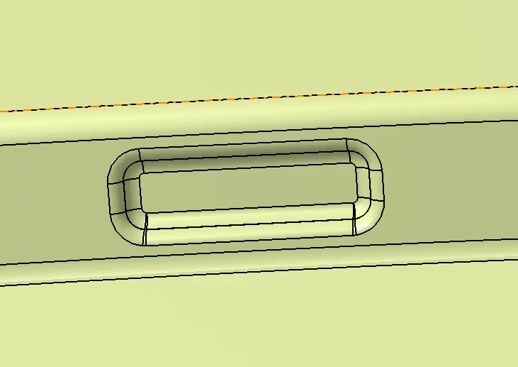
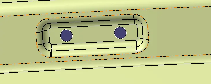
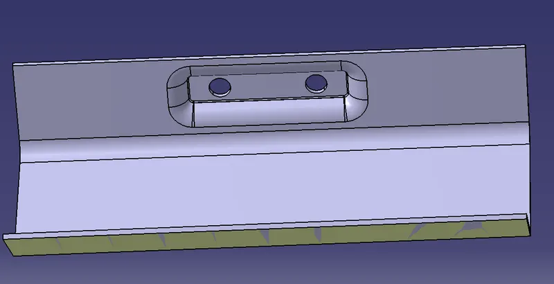
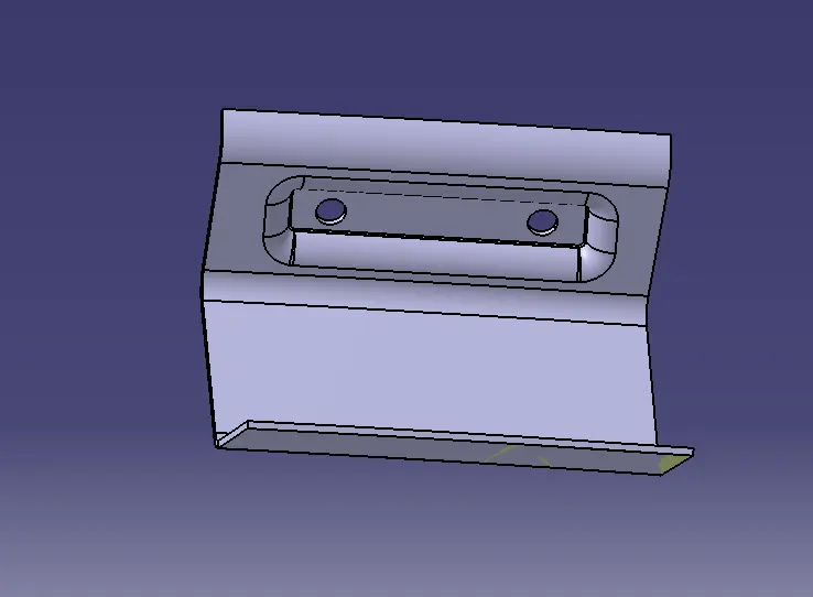
- The gas stays part is created at the side of the inner panel. Follow the same process as the hinge part to create the Gas stay embossment.
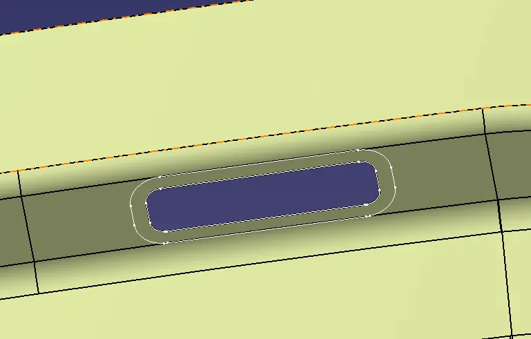
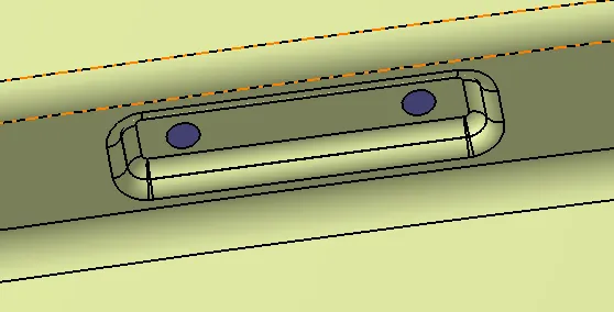
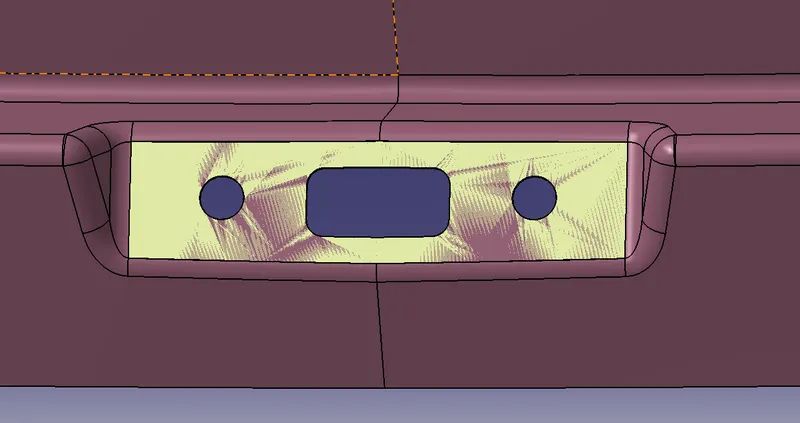
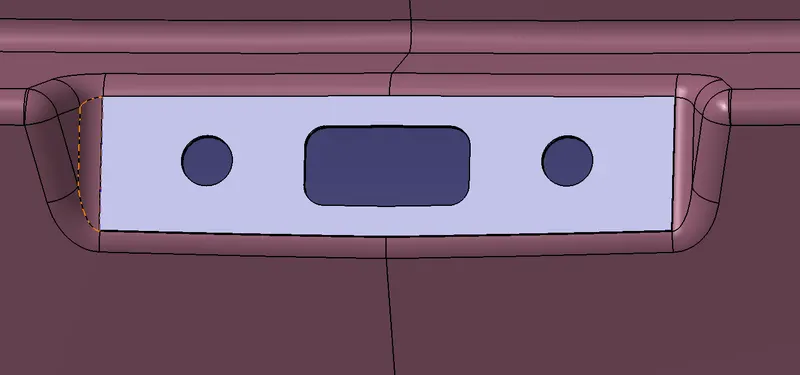
- For the Latch part, we need to create a line with the hinge parts and draw a circle marking the sweep of the lower end of the inner panel. Draw a Tangent to the Circle and create the cut on the tangent area and give the cutouts to it.
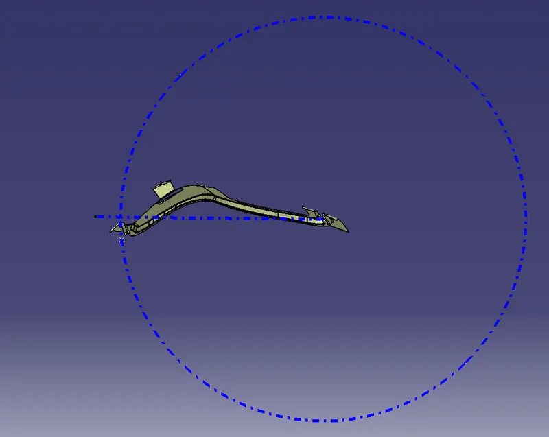
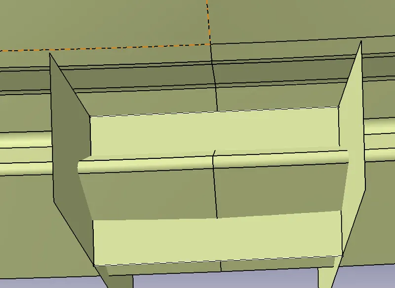
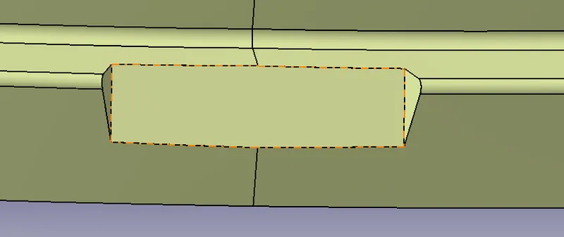
- Give the fillets to the necessary parts.
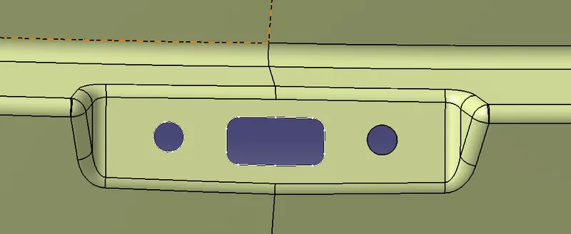
- Creating the Reinforcements:
- To create the reinforcements, select the surfaces with the nearby areas and extract them. Use the line option to create the line on the surface.
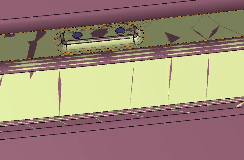
- Split the Surface and select the Surface and offset it to 0.75mm
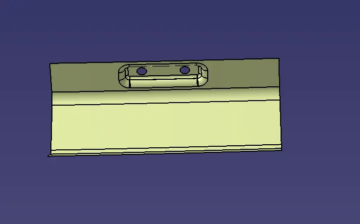 .
.
- Follow the same procedure for the gas stay and latch parts as well.
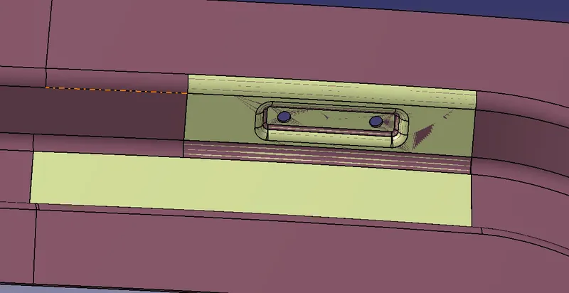
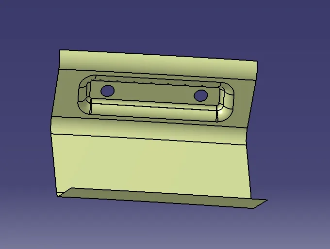
Latch Part:
- Generating a Solid:
- Go to the Part design, Create a New Part Body for the Upper part, Lower part, Inner panel, and reinforcements (each for Hinges, Latch, and Gas stay)
- Use the Thick surface option to create the solid with thick of 0.75mm for back door parts and 1mm for reinforcements.
Result:
The Back door of a car is created along with the necessary reinforcements that help to improve the strength and stability of the back door.
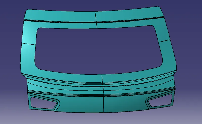
Upper Surface:
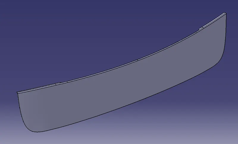
Lower Surface:
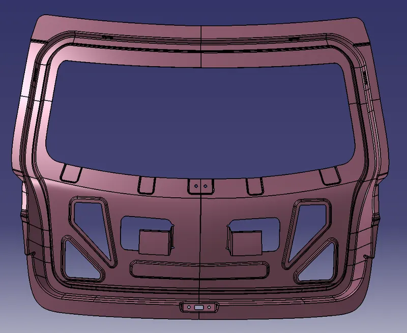
Inner Surface:
Hinge Reinforcement:
Gas Stay Reinforcement:
Latch Reinforcement:
Hemming region:
Reliefs:
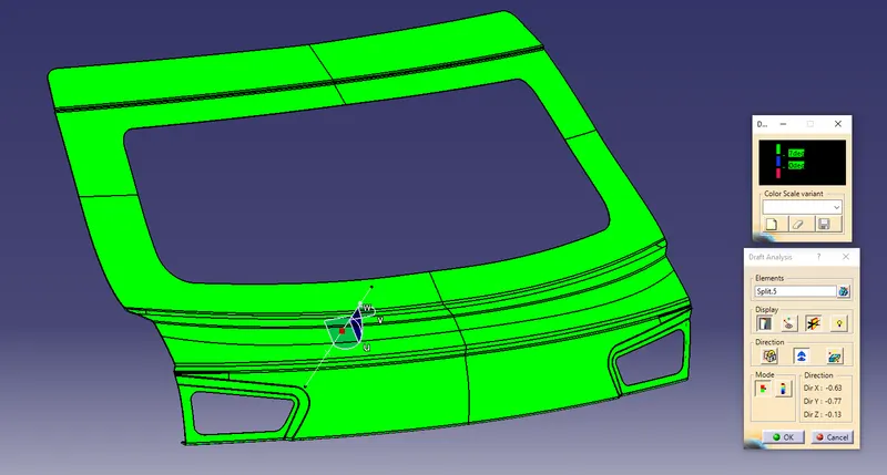
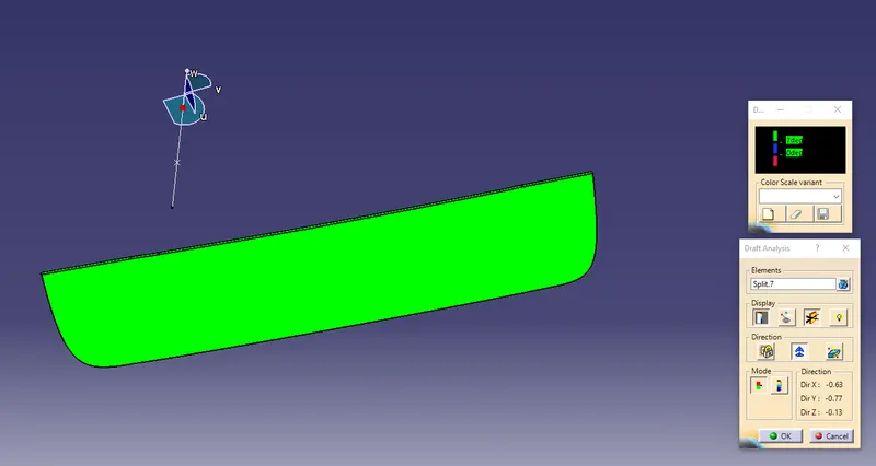
Draft Analysis:
Upper Part:
Lower Part:
Inner part:
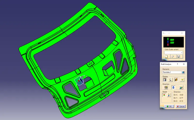
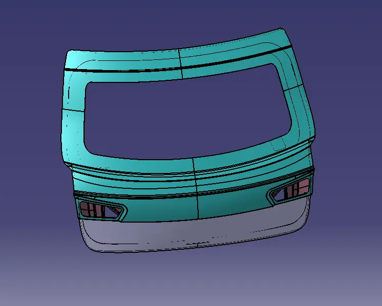
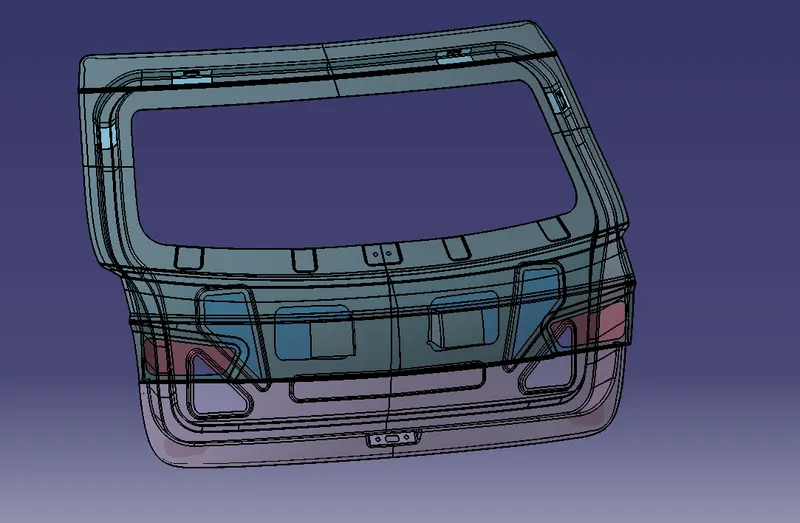
Final Model:
Terms Used:
Hinges:
A hinge is a mechanical bearing that connects two solid objects allowing a limited angle of rotation between them. Two objects are connected by an ideal hinge rotate relative to each other about a fixed axis of rotation.
Latch:
The latch is a mechanical fastener that joins two or more objects or surfaces while allowing for their regular separation. It engages another piece of hardware on the other mounting surface. Depending upon the type and design of the latch, this engaging bit of hardware is known as a keeper or striker.
Gas Stay:
A gas stay or gas spring uses a compressed gas contained within an enclosed cylinder sealed by a sliding piston to pneumatically store potential energy and withstand the external force applied parallel to the direction of the piston shaft.