Challenge

Design of backdoor

                                                CAR BACK DOOR DESIGN

Introduction-

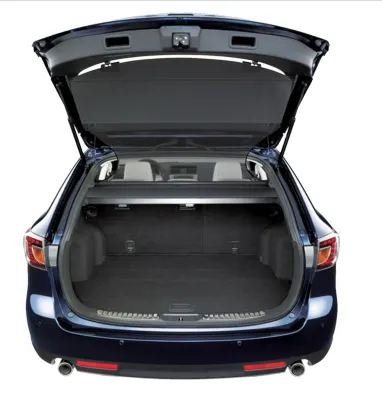
              A Back door or tailgate is a hinged board or door at the rear of a vehicle that can be moved up or down during loading and unloading.The back door or opening of a cargo area may be hinged at the top, side or bottom. If the door is hinged at the bottom it is called a tailgate, particularlyin the united states. They are used on station wagons and pickup trucks, as well as on some sport utility vehicles (SUV).It has tail indicator lights,brake lights,wiper motor area, gas stay, hinge,sealing flange, latch and striker. 
 
 
Manufacturing Processes-
1.Deep Drawing-
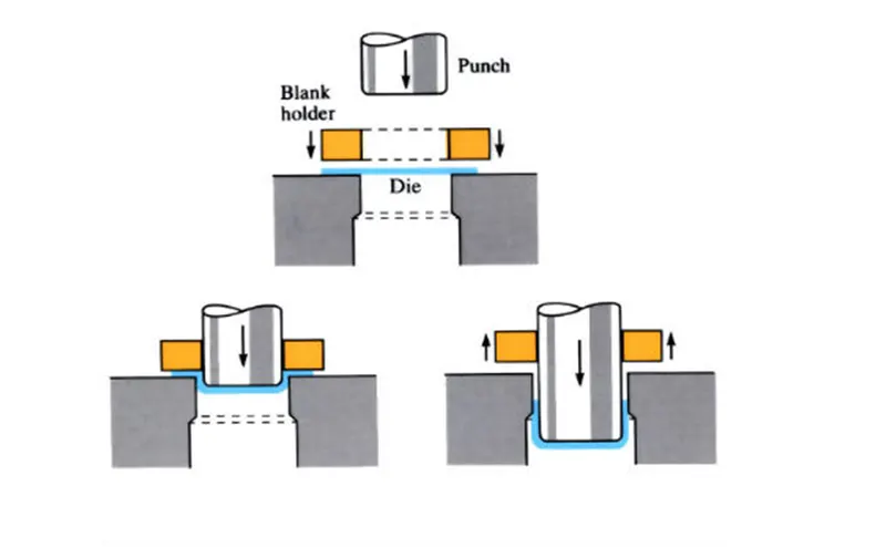
          Drawing is a process of forming flat sheets blanks into hollow shapes by means of a punch that causes the metal to be formed into the die cavity. If the depth is one or more times the diameter of the final shape, then the process is called deep drawing. The deformation limit or the limiting draw ratio (LDR) is the maximum blank diameter that can be drawn into a cup without failure. The draw ratio or the percentage reduction up to 48% on first draw, are considerd achiveable is most ductile material. Embossing the bases of deep drawn components with beads adds rigidity and strength and prevents the phenomenon of dishpanning Mainly mechanical presses up to 1000 tons in capacity are used for deep drawing. 
2. Hemming Process-
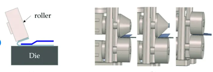
              Hemming is a sheet metal forming process in which sheets are joined by bending it usually to 180*
Automotive body panels and automotive parts such as deck-lids, trunk-lids,door,hoods and tailgates are formed by hemming process. The simplest form of hemming set up is combining two different setups. The first is an acute setup, where the 30deg bend is created using standard tooling. Once the first bend is made the part is either transferred bar and is closed. This setup doesn't require any special tooling and may be preferable for short runs, prototypes or job shops which will need to form a variety of hem lenths. As individual pieces of break press tooling the acute tooling and flattening bar are very verstile and value outside of hemming. The draw backs to this system is the obvious requirements is the obvious requirements of two unique setups, as well there is no thrust control in the flattening process.

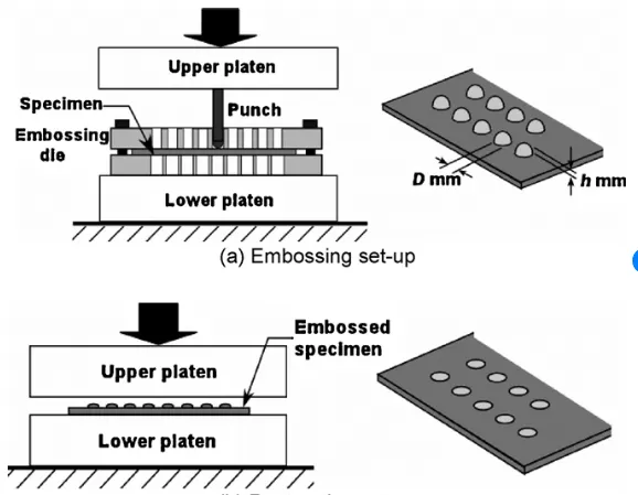
3. Embosing

       The metal sheet embossing operation is commonly accomplished with a combination of heat and pressure on the sheet metal, depending on what type of embossing is required. Theoretically, with any of these procedures, the metal thickness is changed in its composition.

              Metal sheet is drawn through the male and female roller dies, producing a pattern or design on the metal sheet. Depending on the roller dies used, different patterns can be produced on the metal sheet. The pressure and a combination of heat actually "irons" while raising the level of the image higher than the substrate to make it smooth.       

          The term"impressing" refers to an image lowered into the surface of a material, in distinction to an image raised out of the surface of a material.In most of the pressure embossing operation machines, the upper roll blocks are stationary, while the bottom roll blocks are movable. The pressure with which the bottom roll is raised is referred to as the tonnage capacity.

        Embossing machines are generally sized to give 2 inches (5 cm) of strip clearance on each side of an engraved embossing roll. Many embossing machines are custom-manufactured, so there are no industry-standard widths. It is not uncommon to find embossing machines in operation producing patterns less than 6 inches (15 cm) wide all the way up to machines producing patterns 70 inches (180 cm) wide or more.
4. Trimming operation-

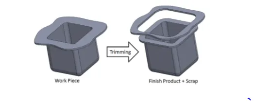
            The shaving operation is another name for trimming. It is a finishing technique that involves removing burrs from cut edges in order to smooth them down and improve dimensional accuracy.
5.Punching operation-

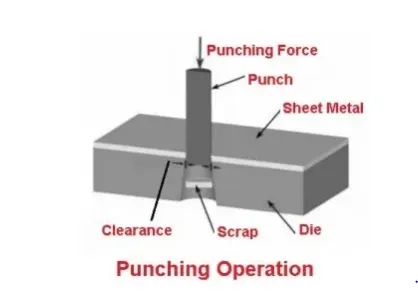
        A punch and die technique is used to create circular holes in a sheet of metal. Although this is the polar opposite of blanking, the process is essentially identical. Blanking processes, for example, require the employment of a punch and die.
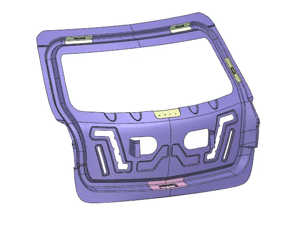
 
Design Methodologies and Component Developed
Input data for components
1.Outer Panel- 0.75 mm
2.Inner Panel- 0.75
3. Reinforcements- 1mm 
 
1. Class a surface-
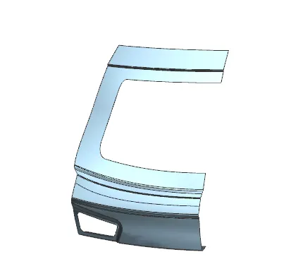
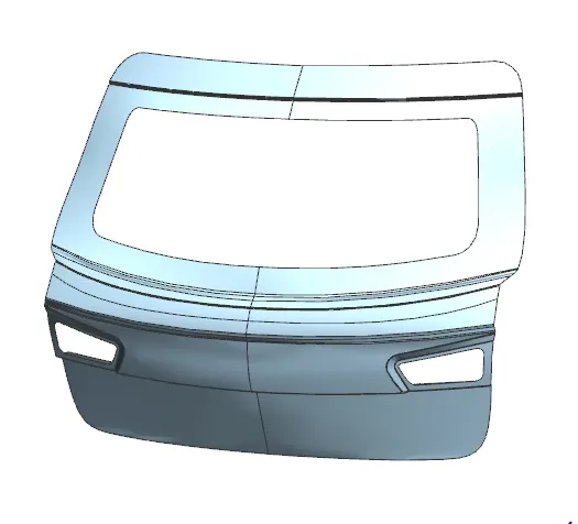
       This is given data provided by styling team for reference design. Outer surface is attched to the inner panel by hemming operation and mastic selant process.
             Outer panel is given in two section outer panel upper and inner. For refernce use we have check the disjoints in given data and sew them to get smooth surface for operations.
 
2. Outer panel-
 
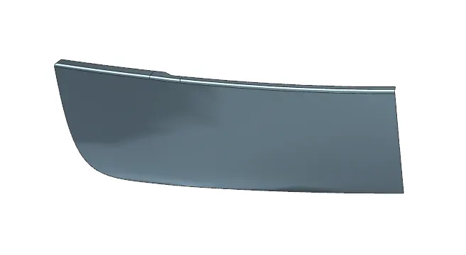
         Outer panel is styling surface which divided into two parts by flange. 
a.upper outer panel
b.lower outer panel 
 
 3. Tooling Direction-
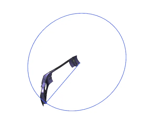
           The back door is going to be manufactured by deep drawing process. In deep drawing process have a tool which is core and die. The core part follows the single stright path the inclination angel of the core is known as a tooling direction. The tooling direction axis is created so,that the manufacturing team take the reference of this tooling axis and manufacturing the part accordingly.
  • Before starting to design the inner panel of the back door the tooling direction for deep drawing purpose should be created.
  • The back door was designed using a top down approach.
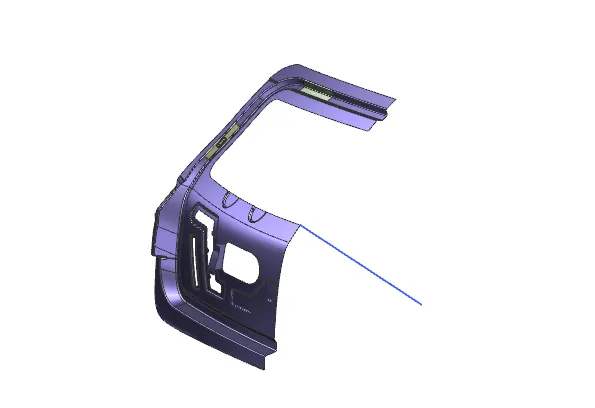
 
4.Inner panel-
          Inner panel is part of back door which gives support to the outer pael of the car and with its embosing shapes dissipate the force in diferent directions when the vehicle takes crashes to not to injure the men in the car.
          
 5. Latch and striker trajectory-
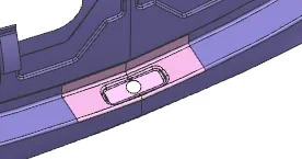
        Door striker are hooks or bolts that latch up the doors on a vehicle. The striker is designed to create a tight fit between the door and the seal on the cab. The trajectory for opening and closing is considered to be proper when the striker's axis is coincidental with the hood center axis. The perpedicular line from this axis is selected from the hinges on either side. 
 

6. Reinforcements-

       Whenever there is an addition of material to the components there is a loss strength locally. In this case the additional material is the striker,wiper mounting,gastay mounting and hinge where additional reinforcement had to be attached due to loss of strength locally in the attachment areas. The thickness of the reinforcement should be in the range of 1.5mm. This parameter can be obtained from CAE team or with carry-over study.

       Distance between the outer and inner panel should be 5mm where mastic sealants are placed in the mastic sealant points to form a strong bond between them. This also reduces the noise and vibration in the hood in the car.

a. Hinge Reinforcement
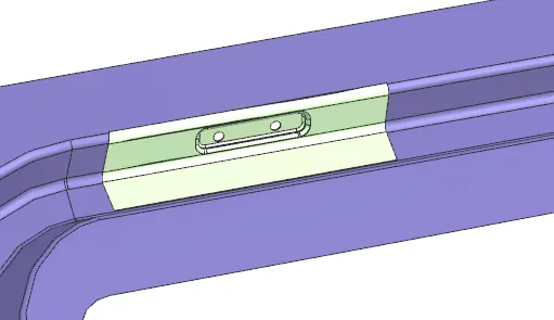
b.Gas stay mounting Reinforcement
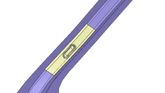
c.Wiper motor mounting reinforcement
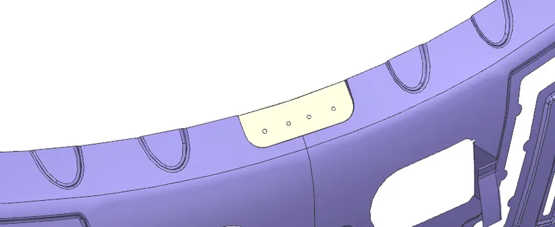
 
 
d.Latch and striker reinforcement
 
 
Draft Analysis
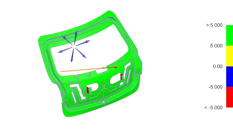
          The draft analysis technique is used to analyze whether our part model created in CAD is manufacturing based on the draft condition applied. Here the part should get easily removed from the panels dies or mold.
 Conclusion-
             The design of back door is done with given styling data. As per design consideration and aspects. 


Your portfolio, next

Ship work like this
in your own course.

Talk to a career counsellor

Free 20-minute call. We'll map the right course to where you want to work.

By submitting you agree to our Terms and Privacy Policy.