Hood design-Week 2
CAR HOOD DESIGN
Intoduction-
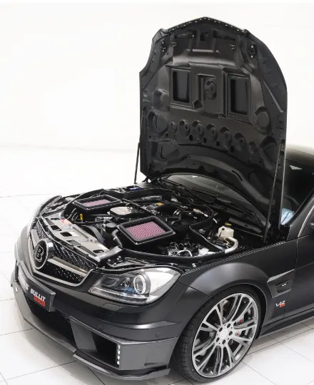
Car bonnet is the important component which is utilized for several purpose at the front. It gives access to the engine compartment which enable the repair and maintenance of many parts namely car engine, radiator etc. Therefore, bonnet must be designed in suitable manner and it should minimize the hindrances from the disturbance caused by the external enviorment on the hood and its components below it. When the car is in running condition resistance force from the air acting on the hood therefore, the design of the bonnet should be made aerodynamic to reduce the air resistance. Hood assembly includes inner panel,outer panel,latche and reinforcements. The upper and stiffener panels are joined through the process of hemming or both panels are joined by using the adhesive namely mastic. Spot weld can be made where it will be necessary. Sandwich construction ot the hood structure that will be increase the capability of the hood's ability to absorb the energy imapcted by the external forces which are acting on the bonnet. The bonnets of the most vehicles are basically fabricated using the sheet metal structure, a good enregy absorbing structure so it causes substantially a small threat.
Outer and inner stiffener panels are made or fabricated by using the of sheet metal structure therefore enviorment used is surface modelling. Since the hood assembly is a sheet metal component, hood structure is vulnerable to the vibration. The souces of vibration could be the engie generated vibrations, the vibrations due to the un-evenness in the rod surface and aerodynamics interactions of the hood surface when the vehicle is in motion. Excessive vibration will put an impact on the passengers ride comfort and also make the structure susceptible fatigue failure. Too many vibrations also affect the fuctioning of the locking mechanism of the bonnet, considerably risking the unlocking fuction and bonnet will be open up while the vehicle is in motion. Because of the many ongoing efforts are to reduce the weight of the vehicle.
Design Aspects
1.Hood opening angel
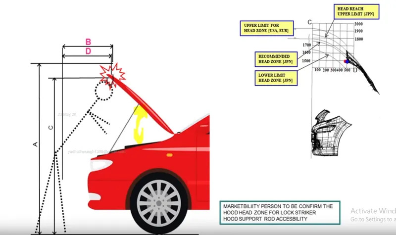
The first important criterion for designing the hood is the opening angle of the hood. This criterion average height of the human in the region of consideration. For example the average height of a human being in india is 5.8 feet whereas in european counteries the average height of a human being is 6 feet. Hence the opening angle of the hood greatly depends on the height of the human which can be controlled by the support rod or gas stay.
The opening angle is considered important criteria because when the opening angle is less there is chance of head injury to the human. By varying the length of the support rod the opening angle can be varied.
2. Pedestrian Saftey
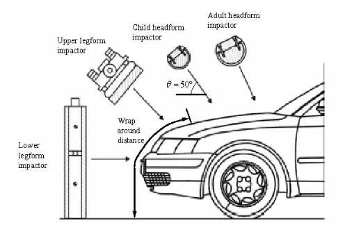
In vehicle to pedestrian collisions, the main reasons for fatal injuries is the pedestrian to vehicle impacts, which are caused by the direct impact of the pedestrian head to the front part of the auotomotive hood during a collision. This paper deals with the development of a new finite elements model to simulate the car-to-pedestrian front impacts between the adult headform and vehicle hood composite structures according to the EURO-NCAP requirments. The pedestrian head impacted by selected three points over the outer structures of the hood with three different inclination angles. The HIC values for engine hood structure with different stacking sequences:[[0,90,45,-45],0,90] [0,90] and [[0,90,45,-45],[0,90]] at 6',8' and 10' inclination angles have been investigated and discussed. The effects of the inclination angles to HIC value, displacement and absorbed energy of the vehicle hood composite structures have been investigated and compared. The results show that foer all the stacking sequences of the hood structure at (A) head impact point,HIC values found to be less than 2000. Which means all the structures at this point with different inclination angles satisfied the requirements of pedestrian saftey. The enregy absorbing found to be higher in (A) head impact point for all the stacking sequences due to the engine hood stifness variation at this point is different compared with other points (B and C). This model can be an appropriated tool for the car-to-pedestrian front impacts evaluation and related development on the composite structure of the hood with different inclination angles.
3. Wrap Around Distance (WAD)
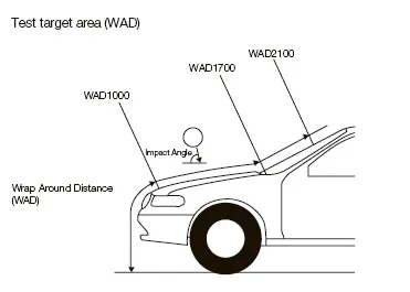
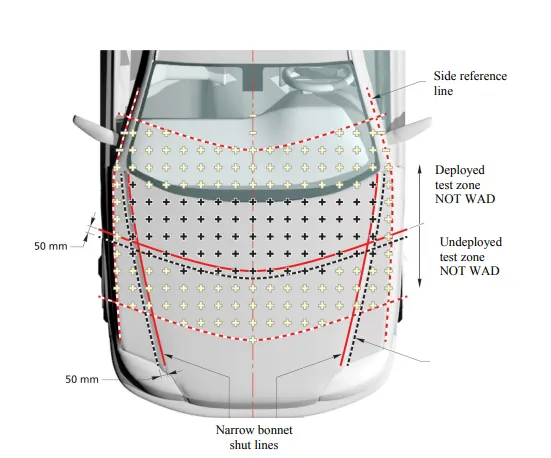
The geometric trace described on the outer surface of the vehicle front structure by one end of a flexible tape, when it is held in a verticle longitudinal plane of the outer surface of the vehicle front structure. The tape is held taut throughout the operation with one end held at the same level as the ground reference plane, vertically below the front face of the bumper and the other end held in contact with front structure. The vehicle is positioned in the normal ride attitude. This procedure shall be followed using alternative tapes of appropriate lenths to describe warp around distance of 1000 mm (WAD1000),of 1700 mm (WAD1700) and of 2100 mm (WAD2100).
4. Latch Trajectory
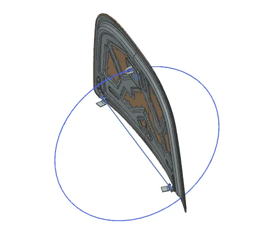
The latch trajectory is the path which the striker will follow when the hood is open/closed while pivoting on the hinge axis. The latch trajectory is taken as a circle with the hinge axis as the center of the circle. The striker is placed 90 degree such that it is tangent to the circle.
5. Mastic Sealant
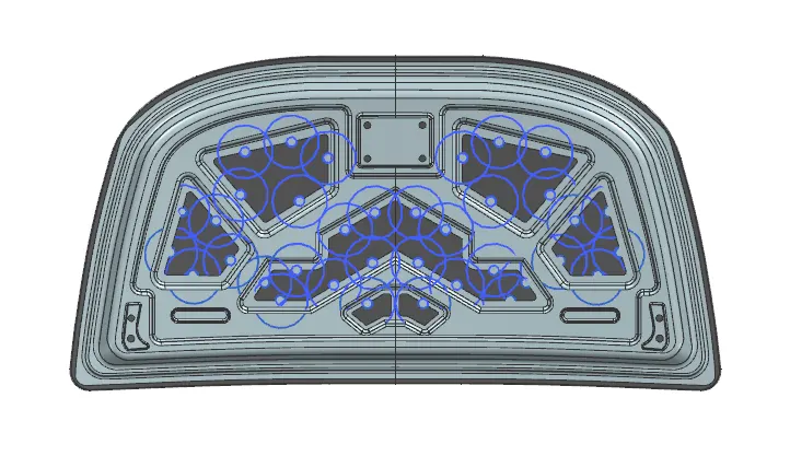
Mastiic sealants are used to stick inner and outer panel together. Mastic sealants are elastic compound that behave like rubber. It is applied between the inner and outer panels at specified points. The mastic points are arranged in such a way that it covers the areas away from the hemming which are more vulnerable to vibrate. Mastic sealants generally have an influence area of about 80mm.
The main application of sealant is to prevent the penetration of water, dust and gas, and to provide resistance to corrosion and sound penetration into the cabin. Sealants used in the vehicle must be resistant to alkaline and acidic materials after assembly of the body and furnace temperature in the paint room, and to withstand friction and vibration during the vehicle's movement.
6. Embose
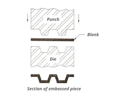
Embossing is generally used to make dimples on sheet metal to increase their rigidity as well as it is also stamping process for producing raised or sunken designs or relief in sheet metal. This process can be made by means of matched male and female roller dies, or by passing sheet or a strip of metal between rolls of the desired pattern. It is often combined with foil stamping to create a shiny 3D effect. The metal sheet embossing operation is commonly accomplished with a combination of heat and pressure on the sheet metal, depending on what type of embossing is required. Theoretically, with any of these procedures, the metal thickness is changed in its composition.
Component of Hood
1.Hood Outer panel
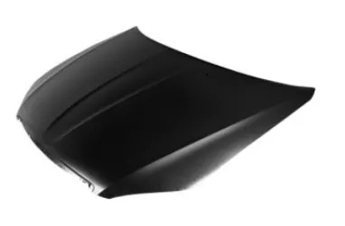
Hood outer panel is the visible part of the hood. Which is desiged based on pedestrian safety norms. It is part which direct contact with pedestrian impact. It is sheet metal part which is made with thickness of 0.5 to 1.5mm. This panel is made from aluminium and other alloy meatls. The panel is manufacture from different processes like Deep drawing, embosing and hemming operation.
2. Hood inner panel
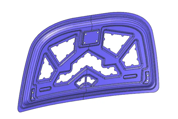
Inner panel is main part of hood which gives the rigidity, support the outer panel and absorb the forces in crash. It consists of different embosses, holes at different section and it has a mastic points to provide stiffness as well as dissipate energy towards the hinges.
3. Support System
a) Support Rod-
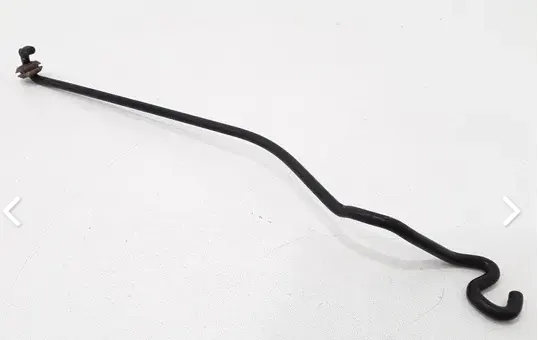
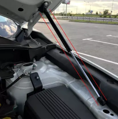
Support rod is basically long cylindrical rod.It safely keep an engine hood in an open state even if external forces are abruptly generated due to vibration & wind. It is cost effective and its bending angle should be less than 35 deg.
b) Gas Stay Support
Gas stay are used in many ways to give mechanical assistance to lifting and supporting components such as car bonnet, boot lids etc. Gas stay work by storing energy in the form of gas under pressure. This stored energy source is kept safe while the structure of the stay is intact. Gas stay contain nitrogen gas under pressure and some oil to damp movement and to lubricate the seals. Operating pressure are typically in the range of 1700 to 15200 kpa (250 to 2200 psi).
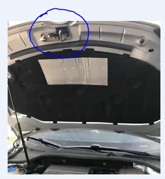
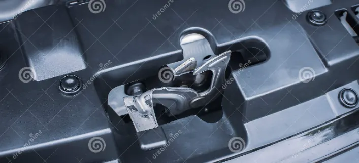
4. Latch Mechanism
Manufacturing Requirements
While designing the inner panel hood that will be manufactured using the deep drawing process, there are some minimum requirments that we need to fulfile.
- Minimum fillet radius= 3mm+Thickness
- No sharp corners inside the component
- No curvature lesser than 5mm
- Small embosses should not exceed the maximum depth of 6mm ( staying on the safe side)
- Mounting areas and welding areas need to be flat
- Provide appropriate corner relief on the area of curvature.
Manufacturing Processes
1. Deep Drawing
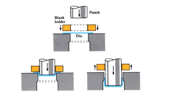
Drawing is a process of forming flat sheet blanks into hollow shapes by means of a punch that causes the metal to be formed into the die cavity. If the depth is one or more times the diameter of the final shape, then the process is called deep drawing. The deformation limit or the limiting draw ratio (LDR) is the maximum blank diameter that can be drawn into a cup without failure.The draw ratio or the percentage reduction up to 48% on first draw, are considered achievable in most ductile materials.Embossing the bases of deep drawn components with beads adds rigidity and strength, and prevents the phenomena of dishpanning. Mainly mechanical presses up to 1000 tons in capacity are used for deep drawing.
2. Hemming
Hemming is a sheet metal forming process in which sheets are joined by bending it usually to 180°. Automotive body panels and automotive parts such as deck-lids, trunk-lids, doors, hoods and tailgates are formed by hemming process. The simplest form of hemming set up is combining two different setups. The first is an acute setup, where the 30° bend is created using standard tooling. Once the first bend is made the part is either transferred to another machine, or a new setup is put into the original. The second setup is a simple flattening bar. The bend is placed underneath the flattening bar and is closed. This setup doesn’t require any special tooling and may be preferable for short runs, prototypes or job shops which will need to form a variety of hem lengths. As individual pieces of Break press tooling the acute tooling and flattening bar are very versatile, and add value outside of hemming. The draw backs to this system is the obvious requirement of two unique setups, as well there is no thrust control in the flattening process. 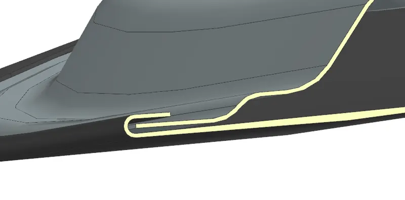
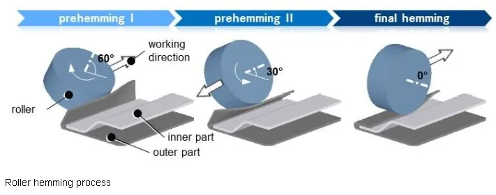
Types of Hemming
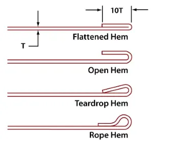
Conclution-
In this challenge I learned design of Inner and outer panel as per parameters and with design aspects.I got valuable knowledge about design and manufacturing processes.