Design of backdoor
Aim:
Use the provided styling surface, use appropriate design methodologies and provide the necessary reinforcements and embosses to design the back door.
Back Door:
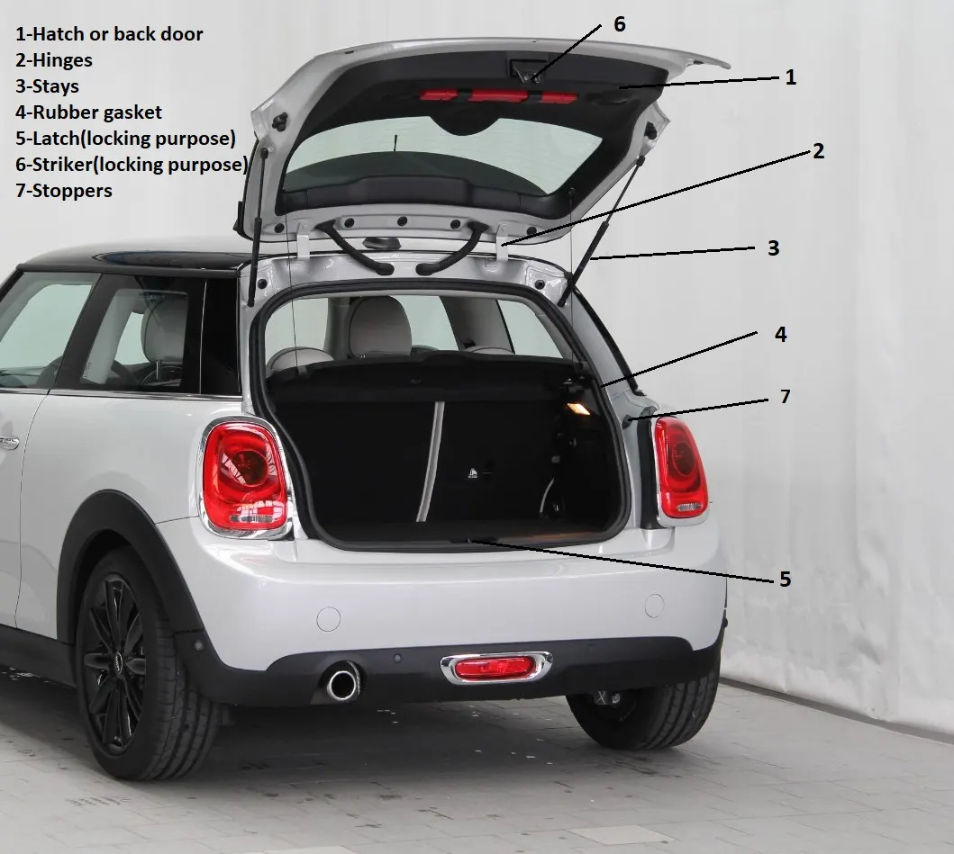
A back door is a BIW component found in all Automotive vehicle generally used for opening and closing of the so called car luggage that is usually used for storing items inside a car. In general the opening and closing of the door is co-ordinated by the Latch and Stricker position and the Gas stay position that is mounted on the body and back door of the car. These positions play a major role in ensuring smooth opening and closing of the tail gate.
Design Considerations In Back Door Design:
The following are the Design considerations taken while designing the Back Door. They are,
- Visibility Criteria
- Force Dissipation
- Latch and Stricker Positions
- Hinge Position
- Gas Stay Position
- Material Selection
- Space Availability
- Hemming and Relief Areas
All these design considerations go hand in hand with eachother because these positions are dependant on each other and if position gets altered all the positions has to be altered for effective opening and closing of the back door. The Latch and Stricker, Hinge Position and the Gas stay Positions has to be maintained in a proper way so that they play a major role in the opening and closing as well as the rear Visibility criteria of the car.
Parts of a Tail Gate:
- Outer Panel Upper
- Outer panel Lower
- Inner panel
- Hinge Reinforcements
- Latch and Stricker Reinforcement
- Wiper Motor Reinforcement
- Gas Stay Reinforcements
All these parts are assembled together to obtain the back door of a car.
Design Methodology:
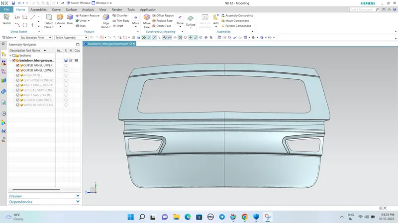
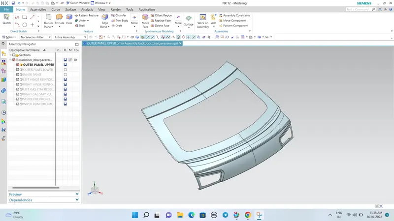
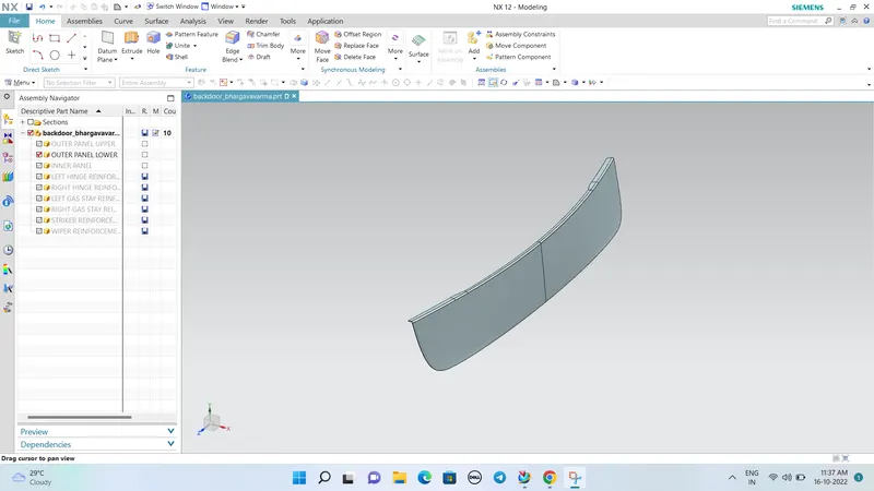
We start with the styling surface that is provided to us, and consider top-down approach for this assembly modeling. First, we create the assembly and then create the components in the assembly file itself. Inner and outer panel are the largest parts and all other parts depend on them so we start with them. Also, the given styling surface is part of the outer panel so we create it first. Using various commands and features we design the outer panel from the styling surface. We have 2 parts for outer panel, which are separated by a flange, hence we create outer panel upper and lower respectively. They will be spot welded with each other. It is necessary to make sure that all the surfaces are properly joint to their adjacent surface and there are no disjoints at their intersection edges to avoid further errors. Also, Inner and outer panels are connected by hemming process so we can come back to outer panel and do that that after completion of inner panel.
Outer Panel
Outer and inner panels are connected by mastic sealants in center and by hemming process at edges. The outer door handle and in some cases, the number plate may also be installed on the outer panel of the back door. We have considered a 2-part outer panel for our design, outer upper panel and outer lower panel prospectively. Outer panel is manufacture by stamping sheet metal. Thickness for outer panel is 0.75 mm.
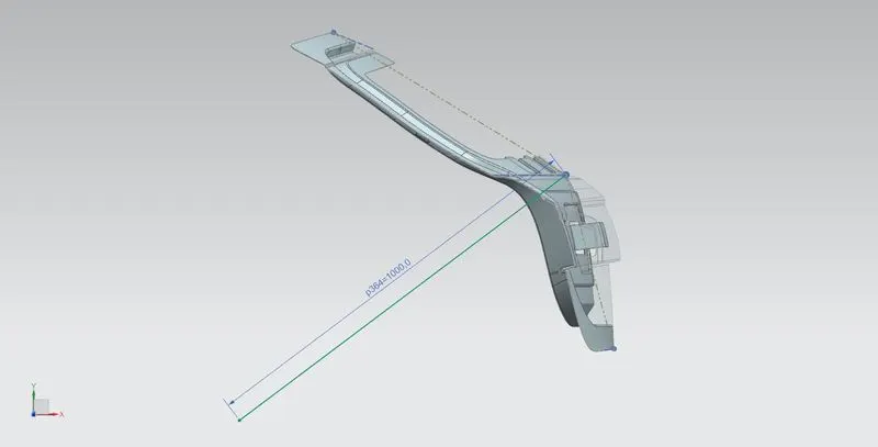
Now, as we know inner panel is at a particular distance from outer panel, we offset the outer panel surface and design inner panel on the same. Inner panel is important as most the mountings will be done on it. Before starting inner panel design, we need to define the tooling direction as a reference for manufacturing team. Then we design the inner panel.
Inner Panel
The inner panel, as the name suggests, is the inner part of the door. It is where most of the reinforcements and components are mounted. It is manufactured either by casting (aluminum) or sheet metal stamping (steel). Thickness of inner panel is 0.75 mm.
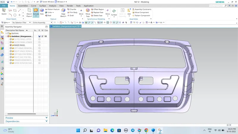
As the inner and outer panel are connected by hemming process, we can complete the hemming after completion of inner panel. Now, as major parts are designed, we can move to reinforcements. It is fairly easy to design reinforcements as we can use the inner panel surfaces using Wave Geometry Linker into the corresponding reinforcement parts.
Hinge reinforcement:
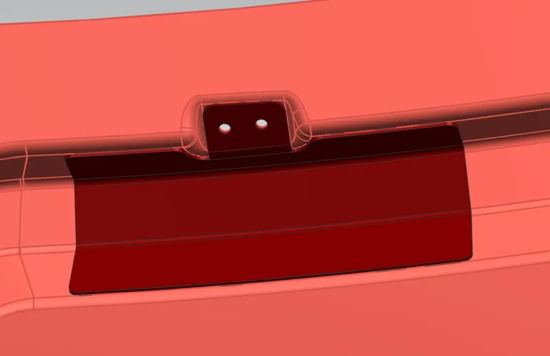
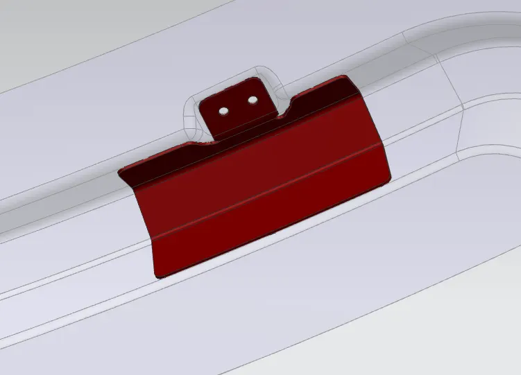
Hinges allow the opening and closing of the back door. One end of the hinge is fixed on the backdoor and the other end on the Roof. Hinges can be placed outside or inside the backdoor.
The hinge reinforcements are added to compensate for the weak region due to the acting load over it.
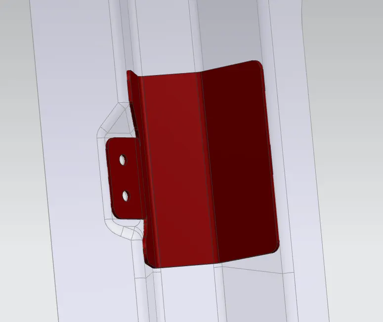
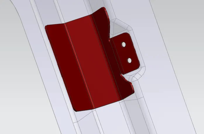
Gas Stay Reinforcement:
Gas Stay is a device used to support the back door in its open position. Gas stay requires no manpower & it is engaged into support position automatically as the back door opens. One end of the Gas Stay is fixed on the backdoor & another end is on the Body Side or on the Back door stationary area.
Embossing is provided at the Gas Stay mounting area to compensate for weakness & improve strength.
Wiper Motor Reinforcement:
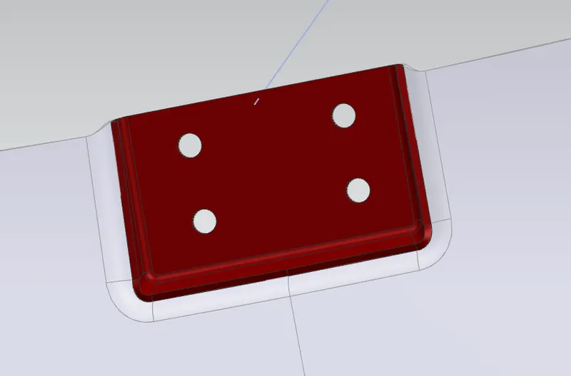
Wiper motor reinforcement is made to mount the wiper motor assembly.
Latch and Striker Reinforcement:
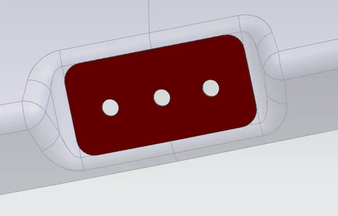
The Latch & Striker together form the locking mechanism of the backdoor with the car. Due to regular opening, closing, and over slamming of the backdoor, there is stress developed in the Latch & Striker area. To recoup for the same, reinforcements are added in this area.
INNER PANEL WITH REINFORCEMENTS:
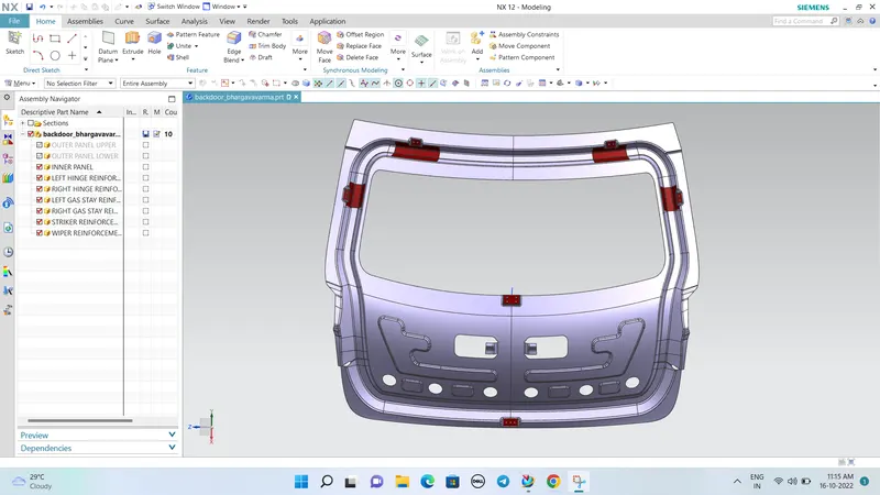
Different Sheetmetal processes used for manufacturing the Back Door
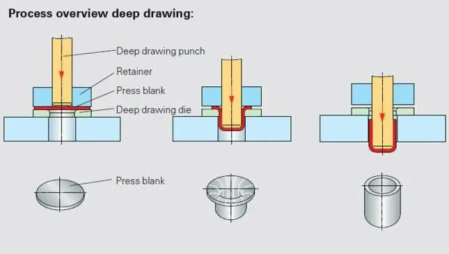
Deep Drawing:
The metal deep drawing process is an effective method of manufacturing of cups, cans and other similar deep drawing products. The deep drawings having two main categories.
- First- stage drawing: The blank shape of metal is placed on the die and contact with the punch. When the metal specimen is flat piece of sheet metal used in forming and finish the product. Initially the punch moves in downward direction. The outer rim of blank is subjected to pure radial drawing (drawing toward in vertical axes) between die and blank metal. The metal become a bend and sliding over die and also stretched between die and punch. The metal in vicinity of punch head and contact with it bend and slide over radii and stretch over punch head.
- Redrawing: The components drawn from first stage again it is redrawn convert into more depth to form a cup shape in the die and punch. The second stage of drawing is called as redrawing.
Embossing:
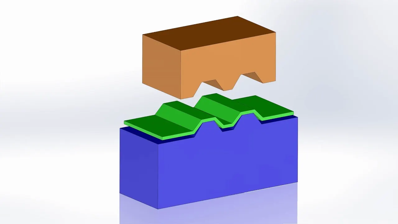
Embossing is a metal forming process for producing raised or sunken designs or relief in sheet materials by means of matched male and female roller dies, theoretically with no change in metal thickness or by-passing sheet or a strip of metal between rolls of the desired pattern. Metal sheet is drawn through the male and female roller dies producing a pattern or design on the metal sheet. Depending on the roller dies used, different patterns can be produced on the metal sheet.
Materials commonly used in the metal embossing process include:
- Aluminum alloys
- Steel alloys
- Zinc
- Copper
- Galvanized steel
- Brass
- Cold rolled steel
HEMMING:
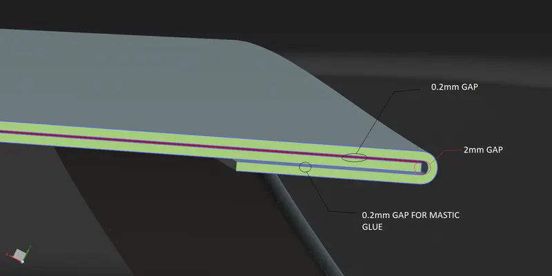
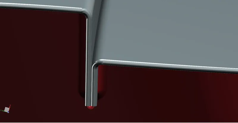
Hemming is the metelworking process in which a sheet metal edge is rolled into itself.The outter surface of the panel is rolled 2 or 3 times over the inner panel.In first roll the panel is bent slinghtly,and in the second roll the shhet matel is rolled even more and in the last roll it completely fits or covered the inner panel.There must be a 0.2mm gap between outter and inner pannel in both upper and lower side.
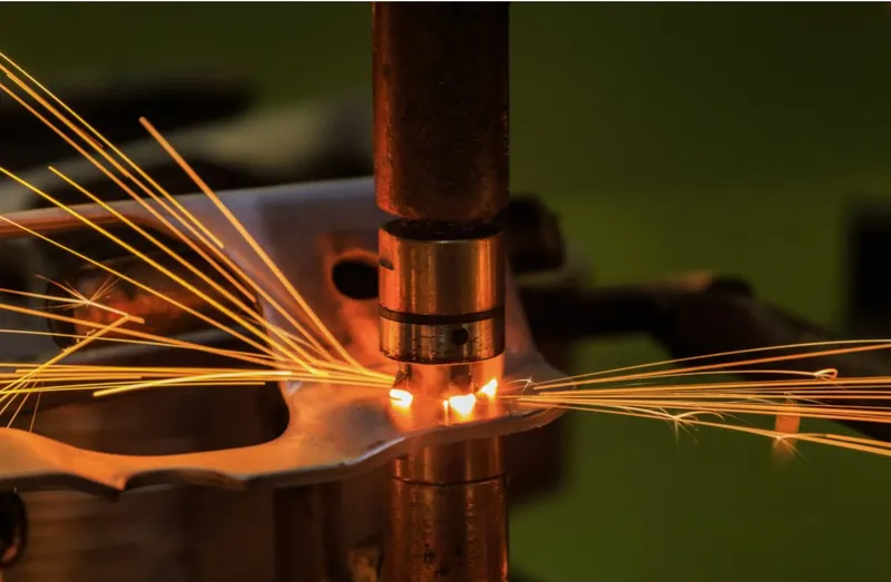
SPOT WELDING:
Another form of resistance welding is Projection Welding. This process involves fusing a fastener’s embossed or coined projections to the metal base material to form a weld. As the materials never melt, they do not intermix. This means the resulting weld is more like a forging of the materials.
Spot welding is only suitable for a small selection of base materials. Low carbon steel is the most suitable material for spot welding. This is because it is more resistant to electricity and has a lower thermal conductivity than the copper electrodes used to create the required electrical current.
High carbon steels and aluminium alloys can form brittle welds that don’t last with the spot welding process. Pure aluminium can qualify for spot welding but requires higher current levels. This is because it has a lower resistance to electricity than low carbon steel.
DRAFT ANALYSIS:
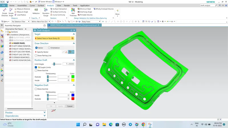
- The draft analysis was performed for the tooling direction created at first and checked that the model is suitable for manufacturing.
- Then to get a complete green portion the required changes to the draft angle of the embosses were carried out by optimizing the model.
- The Draft Analysis command is used to detect that the part drafted will be easily removed or not.
- This type of draft analysis is performed based on color ranges.
- The identifying zones on the analyzed element where the deviation from the draft direction at any point, corresponds to specified values.
Conclusion:
Car back door was designed using the given styling surface on SIMENS NX software.