Design of backdoor
#8 DESIGN OF BACK DOOR
AIM:
To design the Back door (Tail gate) of a car from the styling surface provided using NX CAD.
The ultimate aim is to design the Back Door by following the Industrial Standards.
INTRODUCTION:
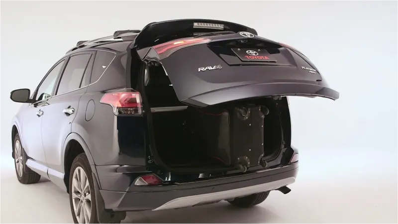
A back door is a BIW component found in all Automotive car generally used for opening
and closing of the so called car luggage that is usually used for storing items inside a car. In general
the opening and closing of the door is co-ordinated by the Latch and Stricker position and the Gas
stay position that is mounted on the body and back door of the car. These positions play a major
role in ensuring smooth opening and closing of the tail gate.
Types of Back Doors:
There are three types of back door based on the position of the Hinge axis. They are
* Top Mounted
* Side Mounted
* Bottom Mounted
DESIGN OF BACKDOOR
The Outer Panel is the styling surface of the back door design. Other components of the
backdoor are designed with reference to the outer panel surface. It acts as the outer cover & deals
with the aesthetics of the car. In this design outer panel is divided into two-part.
* Outer Upper Panel
* Outer Lower Panel
Parts of Back Door:
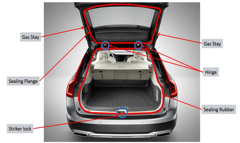
1.Outer Panel
2.Outer panel Lower
3.Inner panel
4.Hinge Reinforcements
5.Latch and Stricker Reinforcement
6.Wiper Motor Reinforcement
7.Gas Stay Reinforcements
Outer Upper Panel:
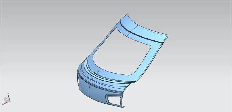
The Outer Upper Panel Extracted from a provided styling surface.
The panel is modified for the required design with the surface tools of NX CAD.
The thickness provided to the outer panel is 0.75 mm.
Hemming is provided with corner reliefs.
Outer Lower Panel:
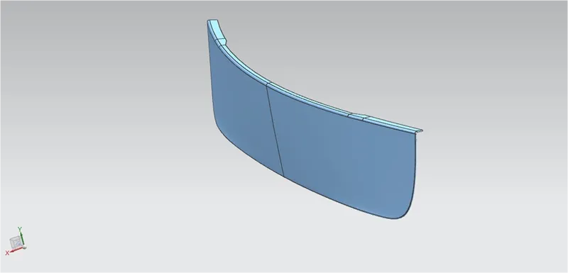
The Outer Upper Panel Extracted from the given styling surface.
The panel is modified for the required design with the surface tools of NX CAD.
The thickness provided to the outer panel is 0.75 mm.
Hemming is provided with corner reliefs.
Tooling Direction:
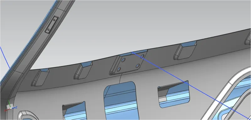
Before starting to design the inner panel of the back door the tooling direction for Deep
Drawing purposes should be created.Then the styling surface needs to be checked properly and
analyzed since it might have irregularities, hence it must be fixed first.
The back door was designed using a top-down approach.
DESIGN OF BACKDOOR INNER PANEL:
The Inner Panel Extracted from a given styling surface.
The panel is modified for the required design with the surface tools of NX CAD.
The thickness provided to the outer panel is 0.75 mm.
MASTIC SEALANT:
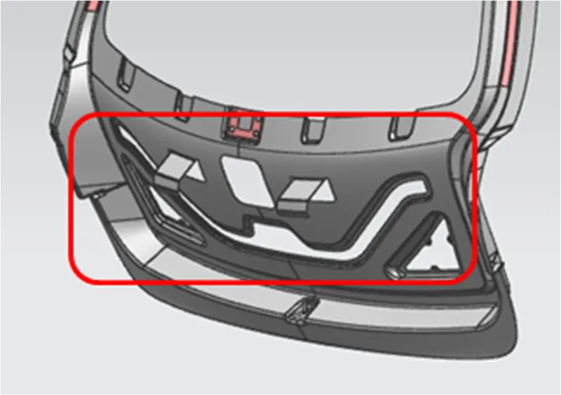
The mastic sealant is used to fix the inner panel and the outer panel which increases the NVH
factor & stiffness of the back door.
HINGE, GAS STAY, WIPER MOTOR & LATCH & STRIKER EMBOSS:
* The GREEN circle denotes the hinge emboss which was created using the datum plane and emboss
feature in NX. It is also designed in a way that the emboss should have a flat surface for
assembling the hinges using it.
* The BLUE circle denotes the gas stay emboss which was created using the surface of the connecting flange.
* The ORANGE circle denotes the Wiper motor emboss which was created using the surface of
the connecting flange.
* The YELLOW circle denotes Latch and Striker emboss were designed by creating a trajectory that follows
the opening and closing of the back door with respect to the axis of the hinge.
Trajectory
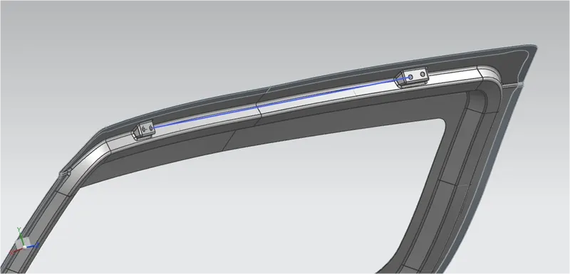
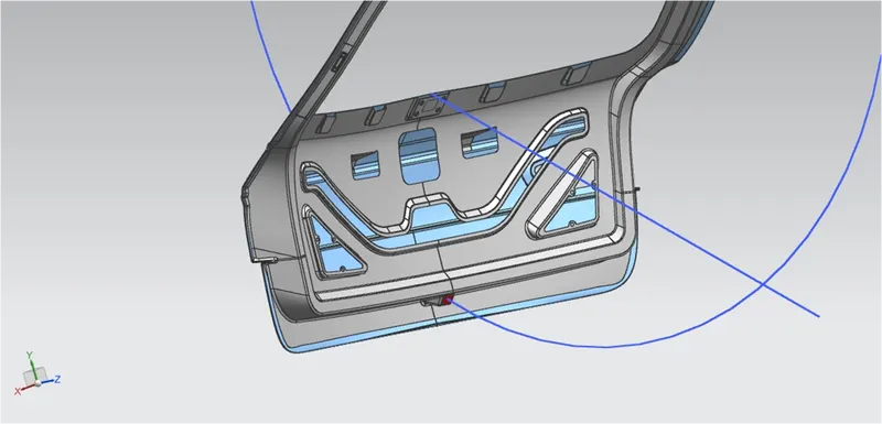
* The position of the hinge should be perpendicular to the latch at the time of latch and striker meets.
* The circle is drawn from the center of the hinge axis to find the path of the striker and perpendicular to the path.
HEMMING:
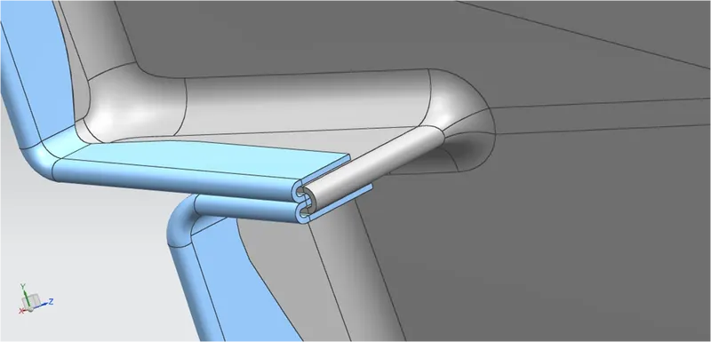
Hemming & seaming are two similar types of metalworking processes in which a sheet metal edge is rolled over
onto itself. Hemming is the process in which the edge is rolled flush to itself.
- The outer panel was designed as two different parts named as outer upper panel and outer lower panel.
- After designing the outer panel the Hemming was created by offsetting the surface with the help of face
- blend & swept surface.
- The two different outer panels will be joined using Blanking
CORNER RELIEF:
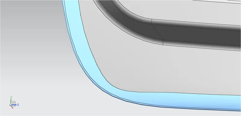
During the hemming process, when giving the Corner Relief helps to control sheet metal material behavior
& to prevent unwanted deformation during unbend operations & also helps to minimize the number of passes in hemming.
DESIGNING THE REINFORCEMENTS:
The thickness provided for all reinforcements is 0.75 mm.
- Hinge Reinforcement
- Gas stay Reinforcement
- Wiper motor Reinforcement
Latch Reinforcemnet
Hinge reinforcement:
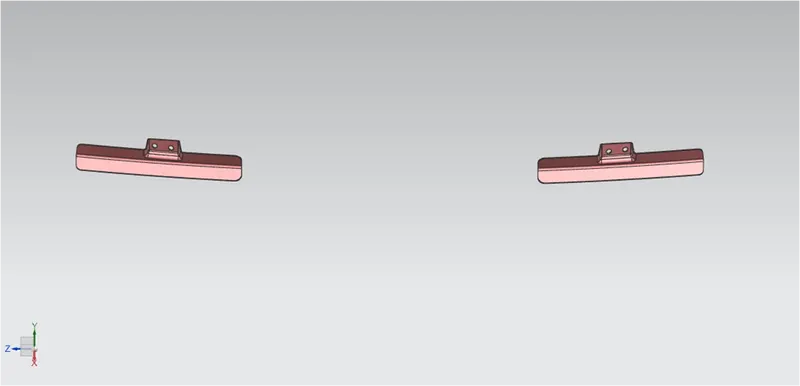
Hinges allow the opening and closing of the back door. One end of the hinge is fixed on the backdoor
and the other end on the Roof. Hinges can be placed outside or inside the backdoor.
The hinge reinforcements are added to compensate for the weak region due to the acting load over it.
Gas Stay Reinforcement:
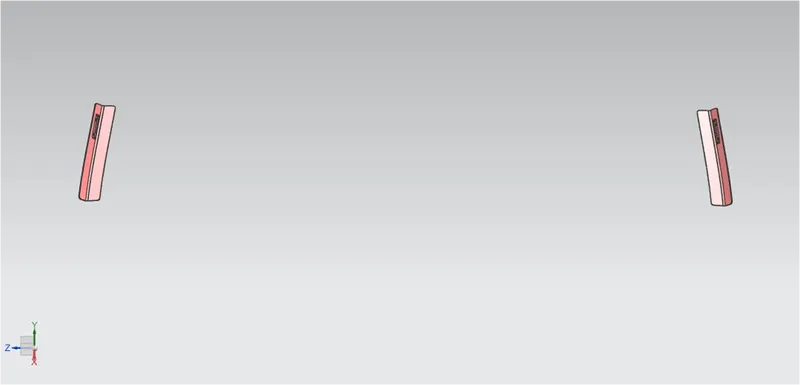
Gas Stay is a device used to support the back door in its open position. Gas stay requires no manpower
& it is engaged into support position automatically as the back door opens. One end of the Gas Stay is
fixed on the backdoor & another end is on the Body Side or on the Back door stationary area.
Embossing is provided at the Gas Stay mounting area to compensate for weakness & improve strength.
Wiper Motor Reinforcement:
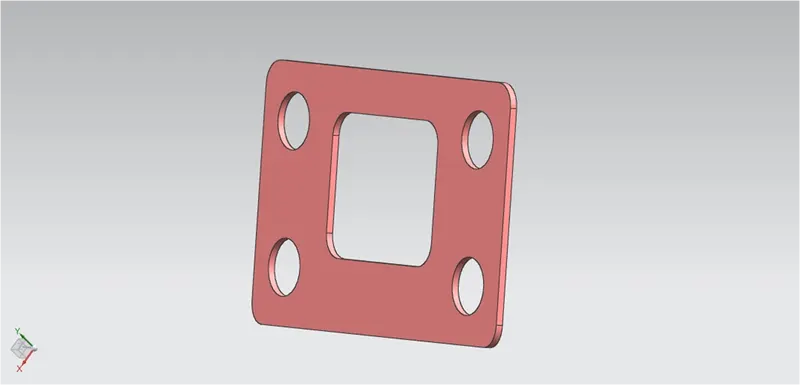
Wiper motor reinforcement is made to mount the wiper motor assembly.
Latch and Striker Reinforcement:
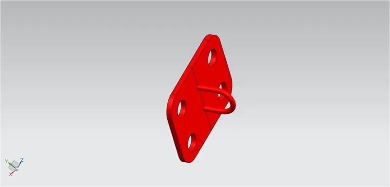
The Latch & Striker together form the locking mechanism of the backdoor with the car. Due to
regular opening, closing, and over slamming of the backdoor, there is stress developed in the Latch & Striker area.
To recoup for the same, reinforcements are added in this area.
Important features used while designing:
Wave Geometry Linker – With this you can create, associative or linked copies of any entity of
a part into other parts. It may be a surface, edge, curve, body, sketch etc.
The changes made to the original entity will be reflected in the copy of that entity.
Extract Body – It is used to create an associative body by extracting faces, entire body or
region of faces.
Bridge Curve – It helps to create a tangent blend curve between two objects. The objects
may be edges or sketch curves.
Sew – It combines sheet bodies together by sewing their common edges. There shouldn’t
be any gaps larger than specified tolerance.
Projected Curve – It is used to project an existing curve/curves on a selected plane or surface
by selecting a direction for projection.
Trim Body – It is used to trim one or more bodies using a face or plane. You can also specify
the bodies to retain and the bodies to discard.
Offset Surface – It allows you to offset one or more existing surfaces.
Offset Curve in Face – This command will allow you to offset particular edges or curves on selected faces.
Trim Sheet – It is used to trim off a portion of a sheet body using curves, faces, edges or planes.
Through Curves – It will allow you to create a body Through multiple sections, where it’s shape
changes to pass through each section.
Law Extension – This command extends a curve or edge to create a sheet body at desired angle
length by changing the rules under angle law and length law.
Trim and Extend – It helps you to trim and extend intersecting surfaces and make corner at their intersection.
Face Blend – It creates fillets between faces.
Edge Blend – It creates fillets on edges.
Extend Sheet – It will allow you to extend an existing surface to required distance.
Emboss – Emboss command creates an embossing by modifying a body with faces created by projecting
a curve/section along a direction. You can modify the emboss using options like endcap location
and draft angle.
Mirror Geometry – As name suggests, it allows you to mirror geometries about selected plane or surface.
Thicken – It is used to convert a surface to solid body by providing thickness.
Extrude – It helps you to create a feature from a sketch. You are also able to create thin feature using
a sketch or curve under this command.
DRAFT ANALYSIS:
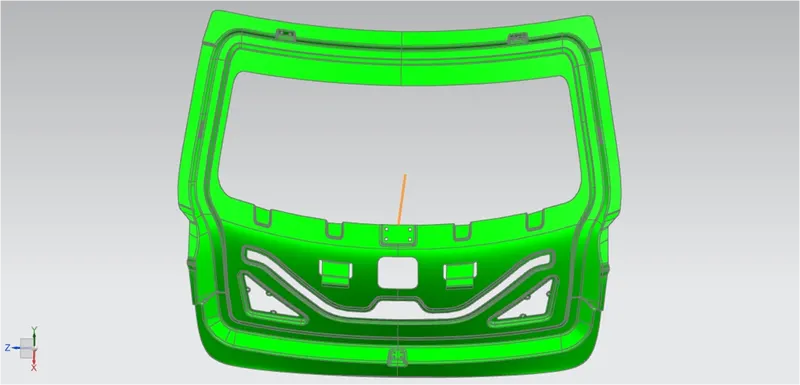
The draft analysis was performed for the tooling direction created at first and checked that the model is
suitable for manufacturing.
Then to get a complete green portion the required changes to the draft angle of the embosses were carried
out by optimizing the model.
The Draft Analysis command is used to detect that the part drafted will be easily removed or not.
This type of draft analysis is performed based on color ranges.
The identifying zones on the analyzed element where the deviation from the draft direction at any point,
corresponds to specified values.
CONCLUSION:
Thus the designing of the Back Door or Tail Gate is done as per Industrial standards and Manufacturing Techniques.