Design and Development of Automobile Backdoor
DESIGN AND DEVELOPMENT OF AUTOMOBILE BACKDOOR
Objective:
The main objective of this project is, to design and develop the automobile back door from the given styling surface with respect to the engineering standards, then to conduct draft analysis of developed design to ensure its tooling feasibility and to provide a detailed report about back door & its parts, design parameters, design procedure, analysis and manufacturing techniques.
Description:
Back boor:

The part which covers the passenger compartment or cargo area at the rear side of an automobile is said to be back door. The main purpose of the back door is to resist the air and water entering into the cargo area or boot space. The back door or opening of a cargo area may be hinged at the top, side or bottom of the body side rear.
If the door is hinged at the bottom, it is called a tailgate, particularly in the United States. They are used on station wagons and pickup trucks, as well as on some sport utility vehicles.
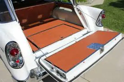
Tailgate model is shown.
Two-way station wagon tailgates may be hinged at the side and the bottom so they can be opened sideways like a regular door, or drop downwards as load platform extenders.
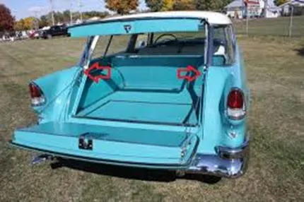
Two-way tailgates are shown in different models.
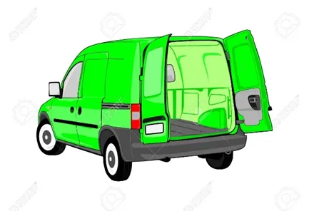
If the door is hinged at the top, it is termed a hatch, and is used on a hatchback.

Hatch is shown.
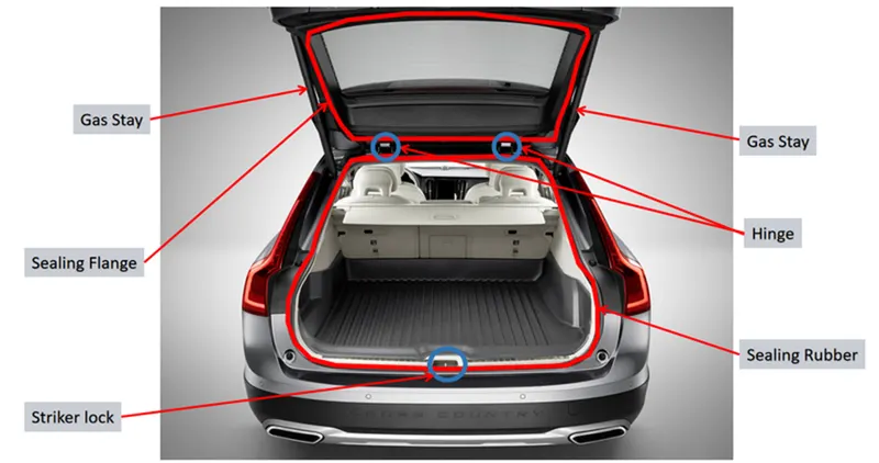
For this project, the given styling surface was a hatch type which is associated with a hatchback or SUV car. The back door comprises outer panel upper & lower, inner panel and the reinforcements.
Design parameters:
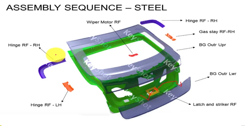
The main parts of a back door are the outer and inner panels. They were further classified into,
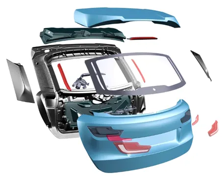
- Outer panel upper
- Outer panel lower
- Inner panel
- Hinge reinforcement LH & RH
- Gas-stay reinforcement LH & RH
- Wiper motor reinforcement
- Latch & striker reinforcement.
There are certain engineering standards to design the automobile roof. These standards are derived from trial-and-error method to reduce the material wastage, production cost and to improve the safety over the years. These standards may vary region to region according to the conditions, usage, rules and regulations of that particular region.
The following parameters are very important while designing a back door,
- The thickness of 0.75mm should be maintained for all the parts of back door unless and until it requires more thickness to improve strength and the thickness must be uniform throughout the part with some allowed tolerance.
- All the blends of parts should have at least (3+t) mm (t-thickness of the part) to avoid stress concentration and shrinkages over the surface.
- All sharp corners of parts should be blended to improve the tool life.
- The hemming surface of the outer panel is maintained between (6-8 mm + blend radius) and the reliefs at the corners is mandatory to avoid overlapping and shrinkage over the corners.
- There should be 0.2mm of tolerance between the outer panel and inner panel at the hemming area for the sealants.
- The sealing flange of inner panel should have minimum of 25mm width to land over the rubber sealant which is connected at body side rear.
- Hinge, gas-stay, wiper motor and latch & striker are the external parts which is going to be assembled with back door inner panel. So, the inner panel must have provisions to accommodate all these external parts with a flat surface.
- According to studies, the efficient way to distribute the load at a certain region is creating a v or y embosses and these embosses should have a minimum of 7º positive draft to make the part feasible to manufacture.
- Those drafts were maintained positive with respect to the tooling direction.
- Clearance between the outer & inner panels should be minimum and it does not affect the boot space or cargo space.
- If the mastic sealants are going to be used to assemble the panels, then the clearance of 5mm is must between the panels to accommodate the sealants to expand.
- There should be 3-5 mm of clearance between the edges & blends, holes & blends, and blends-blends of flanges.
- All the reinforcements are to be 1.5mm thick to improve the strength at mounting regions.
- Inner panel should have necessary clearance to assemble the wiper motor and other external parts in it.
Design procedure:
Design procedure of a back door starts with examining the surface tangency and continuity of the given styling surface. This is to avoid the error at the early stages.
Styling surface: it is the exterior surface which is visible and also considered as aesthetics of part which depicts the final product in 3D.
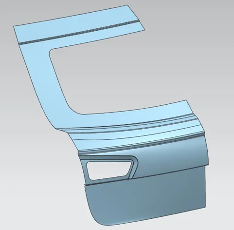
styling surface.
The surface tangency and continuity of the styling surface can be verified by applying the ‘sew’ command and check for results. If any gaps present between the surfaces is highlighted now. In this condition we have to inform these issues to the styling team to correct it and the minor issues can be corrected ourselfs, but it should be conveyed to the styling team.
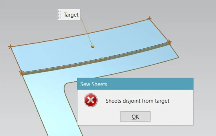
Issues in styling surface is shown.
For the given styling surface, there are so many gaps and discontinuity are identified. The surfaces having issues are recreated to maintain the smooth surface to avoid poor aesthetics of the door.
In this project, top to down approach is used to design and develop the back door. In this method, an assembly file is created first and then the part models are created within this assembly. This is to simplify the assembly of back door parts.
- Outer panel upper:
Outer panel are considered as aesthetic part of the back door. It is only the visible part of back door.
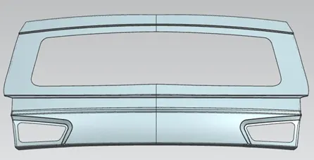
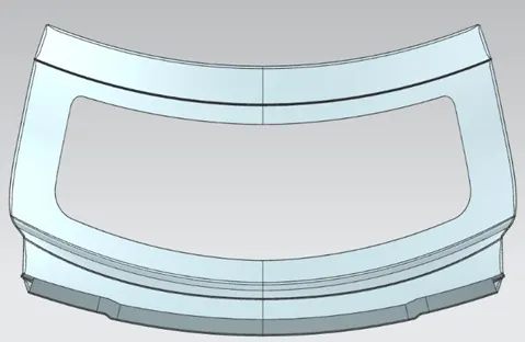
Outer panel upper in different views is shown.
- The reference surfaces are taken from the styling surfaces file by creating a new part file and copy/pasted the reference surfaces into the new file.
- This surface is to be considered our input for the outer panel upper.
- The sharp corners were trimmed off by creating bridge curves over the required corners. The trimming of surface is done by the ‘trim sheet’ command.
- Then the surface is offset to (0.75+0.2+0.75+0.2+0.75) mm downwards to create hemming flange.
- Using the ‘offset curve in face’ command the outer edge of offset surface is offset to 7mm inwards.
- And the unwanted regions were trimmed of using this offset curve and ‘trim sheet’ command.
- Then bridge curves were created between the working surface and offset surface to create blend.
- By using the ‘swept’ command with respect to the bridge curve and edges of the surfaces, blend between the surfaces were created.
- At the corners and steps of the hemming flange, reliefs were created using the ‘curve on surface’ and ‘trim sheet’ commands.
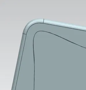
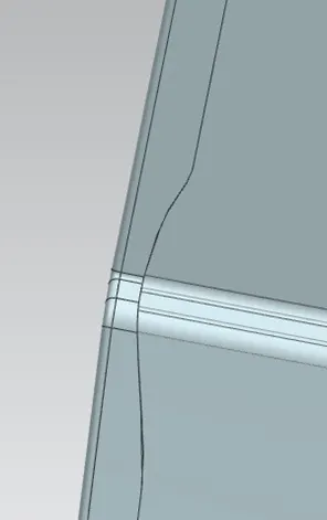
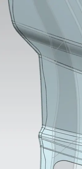
Hemming reliefs are shown.
- After creating hemming flange, the surface is extended at the 0Y position and trimmed off with respect to XY plane.
- Then by applying the ‘mirror geometry’ command, the surface is mirrored about the XY plane, then those surfaces were sewed together and finally ‘thicken’ command is applied to create the solid part of outer panel upper.
- Outer panel lower:
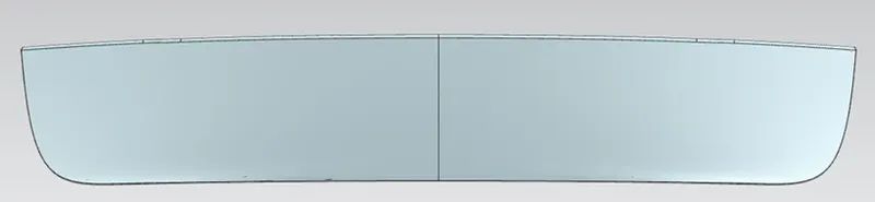
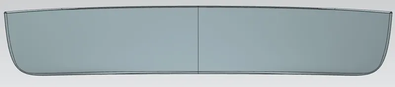
Outer panel lower in different views is shown.
- The reference surfaces are taken from the styling surfaces file by creating a new part file and copy/pasted the reference surfaces into the new file.
- This surface is to be considered our input for the outer panel lower.
- Then the surface is offset to (0.75+0.2+0.75+0.2+0.75) mm downwards to create hemming flange.
- Using the ‘offset curve in face’ command the outer edge of offset surface is offset to 7mm inwards.
- And the unwanted regions were trimmed of using this offset curve and ‘trim sheet’ command.
- Then bridge curves were created between the working surface and offset surface to create blend.
- By using the ‘swept’ command with respect to the bridge curve and edges of the surfaces, blend between the surfaces were created.
- At the corners of the hemming flange, reliefs were created using the ‘curve on surface’ and ‘trim sheet’ commands.
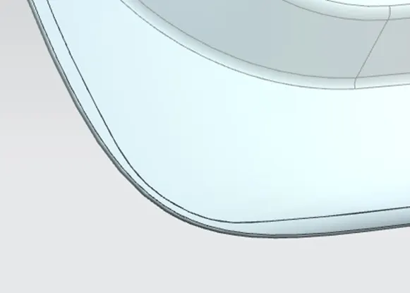
Hemming relief is shown.
- After creating hemming flange, the surface is extended at the 0Y position and trimmed off with respect to XY plane.
- Then by applying the ‘mirror geometry’ command, the surface is mirrored about the XY plane, then those surfaces were sewed together and finally ‘thicken’ command is applied to create the solid part of outer panel lower.
- Inner panel:
Inner panel are the part where the external parts and outer panel are going to be assembled with and it is considered as engineering part.
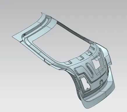
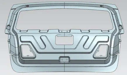
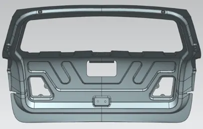
Inner panel in different views are shown.
- As, we seen before, the input or reference surface were taken from the outer panel upper and lower, but this time ‘wave geometry linker’ command is used.
- The reference surfaces were extracted here using ‘extract geometry’ command. The extracted surfaces are our working surfaces and reference surfaces are our inputs for inner panel.
- The inner panel design starts with the creation of sealing flange. “Sealing flange” is the surface which is going to be laid down over the dynamic rubber sealant of body side rear to make the compartment air and water tight. This is the surface where whole door going to have contact between the body side rear in rest position.
- The working surface is offset to the required distance using the “offset surface” command.
- Then the required edges were offset on the surface using the “offset curve in face” command.
- With help of these offset curves, the unwanted regions were trimmed off using the “trim sheet” command.
- The gaps between the upper and lower surfaces were filled by creating ‘bridge curves’ at the required edges and using the ‘through curve mesh’ command.
- Those surfaces were joined together using ‘sew’ command, then the sewed surface is extracted and all the created surface were added to a feature group and named it as ‘sealing flange’.
- After this, the working surface is offset again to the required distance and the sealing flange edges are extended using the ‘law extension’ command until overlaps with the offset surface.
- “Trim and extend” command is applied to trim the unwanted regions and make corners.
- Those corners are blended using ‘edge blend’ command. After this, the working surface is offset like before, but now the lower and upper offsets were connected by creating a surface between them.
- This can be done with the help of bridge curve and through curve mesh commands.
- Now, the embosses for hinge mount, ga-stay mount, wiper motor mount, latch & striker mount and v emboss were created using the newly created sketches and datum planes.
- Their corners were blended using the ‘edge blend’ command and holes for mounting were created by trimming the surface.
- For the latch & striker emboss, the latch trajectory is assumed.
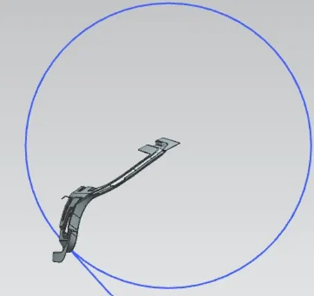
Latch trajectory is shown.
- Once the surface creations are completed, the entire surface is mirrored about XY plane using ‘mirror geometry’ command and joined using the ‘sew’ command.
- Finally, the inner panel surface is thickened using the ‘thicken’ command and the left-out sharp corners or edges were blended using solid ‘edge blend’ command.
- Hinge reinforcement LH & RH:
Reinforcements are the parts which is used to support the inner panel locally to improve strength while mounting or assembling the external parts to it.
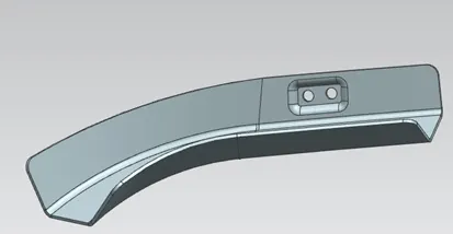
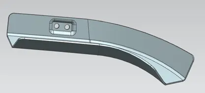
Hinge reinforcement LH & RH are shown.
- For this, the reference surfaces are taken from the required areas of inner panel using the ‘wave geometry linker’ command.
- This surface is the input for hinge reinforcements. The unwanted surface was trimmed off with the help of datum planes and ‘trim sheet’ command.
- Then this surface is thickened to create solid part using the ‘thicken’ command and the sharp edges were blended using the solid ‘edge blend’ command.
- Once the part creation was done, then this part is mirrored about the XY plane and created part is saved as separate part file.
- Gas-stay reinforcement LH & RH:
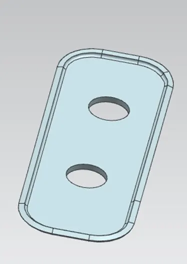
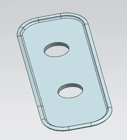
Gas-stay reinforcement LH & RH are shown.
- For this, the reference surfaces are taken from the required areas of inner panel using the ‘wave geometry linker’ command.
- This surface is the input for gas-stay reinforcements.
- Then this surface is thickened to create solid part using the ‘thicken’ command.
- Once the part creation was done, then this part is mirrored about the XY plane and created part is saved as separate part file.
- Wiper motor reinforcement:
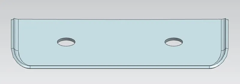
Wiper motor mount reinforcement is shown.
- For this, the reference surfaces are taken from the required areas of inner panel using the ‘wave geometry linker’ command.
- This surface is the input for wiper motor reinforcements.
- Then this surface is thickened to create solid part using the ‘thicken’ command.
- Latch & striker reinforcement:
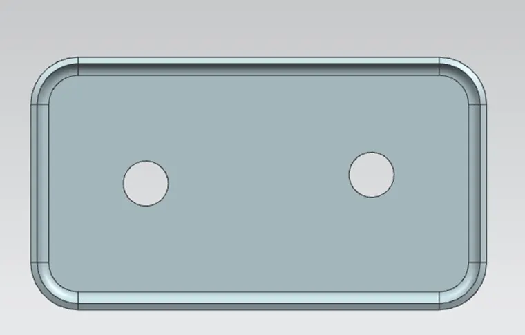
Latch & striker reinforcement is shown.
- For this, the reference surfaces are taken from the required areas of inner panel using the ‘wave geometry linker’ command.
- This surface is the input for latch & striker reinforcements.
- Then this surface is thickened to create solid part using the ‘thicken’ command.
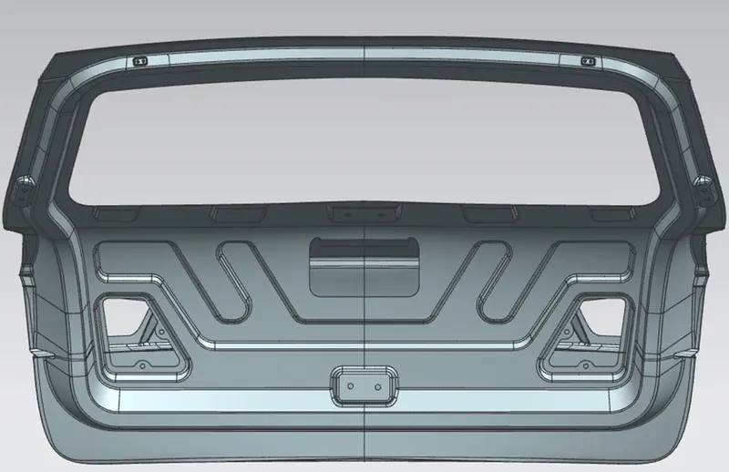
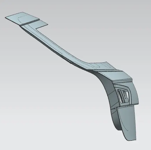
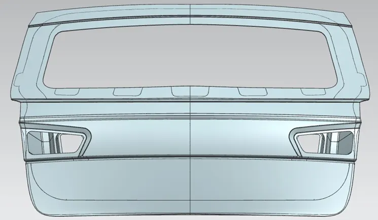
Different views of backdoor assembly is shown.
Analysis:
For this project the following analysis was done to check the tooling feasibility,
Draft analysis:
Draft analysis is used to find the feasibility to manufacture the deigned part using the appropriate manufacturing techniques. The minimum draft angle for sheet metal parts is 7º. This draft angle should be maintained in the design to ease the ejection of tool or part. This can be calculated using the ‘draft analysis’ command. To do the draft analysis we have to decide the tooling direction of the part. With respect to this tooling direction, draft analysis is carried out with angle limited to 7º. If the surface were changed into green colour, then the part is passed in draft analysis and it is feasible to manufacture the part. But if the surface changed into yellow or red colour then those surfaces have to be corrected until it changes to green.
For this project, the tooling direction for back door outer panel upper & lower, inner panel, and its reinforcements were created individually in the part level and the draft analysis are also done for all the parts.
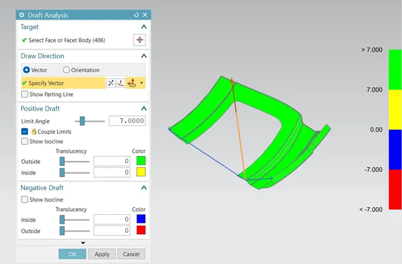
Draft analysis sample is shown.
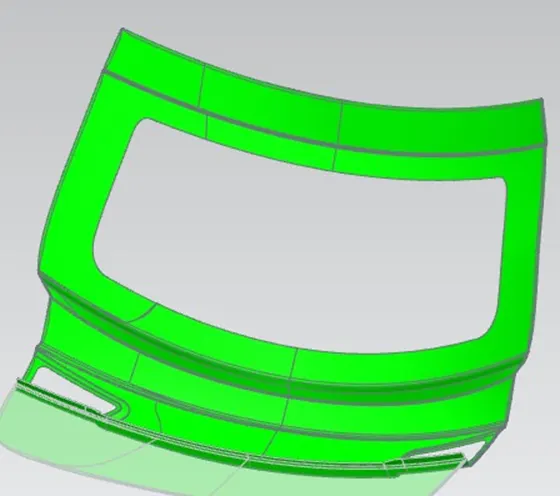
Draft analysed outer panel upper.
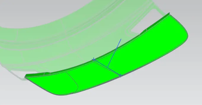
Draft analysed outer panel lower.
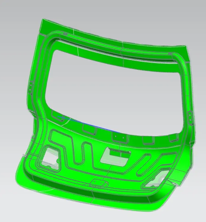
Draft analysed inner panel.
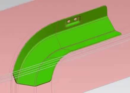
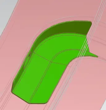
Draft analysed hinge reinforcements.
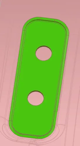
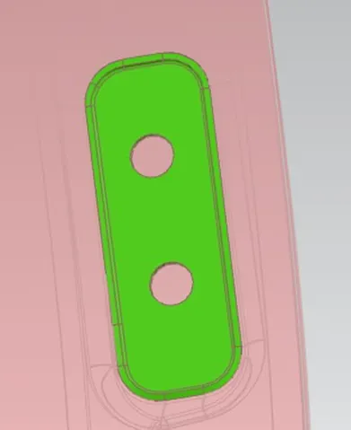
Draft analysed gas-stay reinforcements.
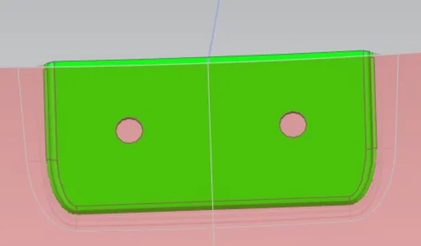
Draft analysed wiper motor reinforcement.
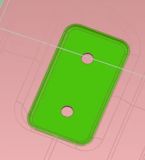
Draft analysed latch & striker reinforcement.
Manufacturing techniques:
The OEMs and automotive industry commonly use the manufacturing processes like,
- Deep-drawing and
- Hemming.
Deep-drawing:
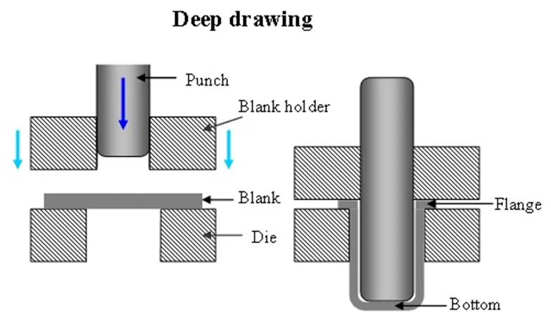
Deep-drawing is a sheet metal forming process in which a sheet metal blank is radially drawn into a forming die by the mechanical action of a punch. It is thus a shape transformation process with material retention. The process is considered “deep” drawing when the depth of the drawn part exceeds its diameter. This is achieved by redrawing the part through a series of dies. The flange region (sheet metal in the die shoulder area) experience a radial drawing stress and a tangential compressive stress due to the material retention property. These compressive stresses (hoop stresses) result in flange wrinkles. Wrinkles can be prevented by using a blank holder, the function of which is to facilitate controlled material flow into the die radius.
Deep drawing has been classified into conventional and unconventional deep drawing. The main aim of any unconventional deep drawing process is to extend the formability limits of the process. Some of the unconventional processes include hydromechanical deep drawing, hydroform process, aquadraw process, Guerin process, marform process and the hydraulic deep drawing process to name a few.
Industrial uses of deep drawing processes include automotive body and structural parts, aircraft components, utensils and white goods. Complex parts are normally formed using progressive dies in a single forming press or by using a press line.
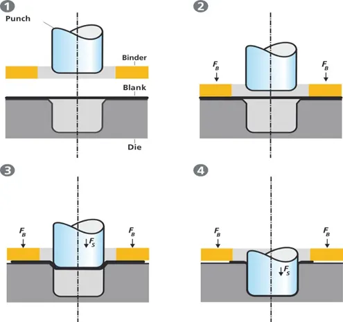
Working materials and power requirements:
Softer materials are much easier to deform and therefore require less force to draw. The following is a table demonstrating the draw force to percent reduction of commonly used materials.
|
Drawing force required for various materials and reductions [kN] |
||||
|
Material |
Percent reduction |
|||
|
39% |
43% |
47% |
50% |
|
|
Aluminium |
88 |
101 |
113 |
126 |
|
Brass |
117 |
134 |
151 |
168 |
|
Cold-rolled steel |
127 |
145 |
163 |
181 |
|
Stainless steel |
166 |
190 |
214 |
238 |
Tool materials:
Punches and dies are typically made of tool steel, however cheaper (but softer) carbon steel is sometimes used in less severe applications. It is also common to see cemented carbides used where high wear and abrasive resistance is present. Alloy steels are normally used for the ejector system to kick the part out and in durable and heat resistant blank holders.
Lubrication and cooling:
Lubricants are used to reduce friction between the working material and the punch and die. They also aid in removing the parts from the punch. Some examples of lubricants used in drawing operations are heavy-duty emulsions, phosphate, white lead and wax films. Plastic films covering both sides of the part while used with a lubricant will leave the part with a fine surface.
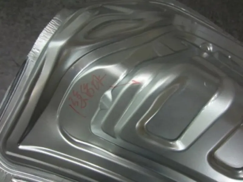
Deep drawn part is shown.
Hemming:
Hemming is a forming operation in which the edges of the sheet are folded or folded over another part in order to achieve a tight fit. Normally hemming operations are used to connect parts together, to improve the appearance of a part and to reinforce part edges.
In car part production, hemming is used in assembly as a secondary operation after deep drawing, trimming and flanging operations to join two sheet metal parts (outer and inner) together. Typical parts for this type of assembly are hoods, doors, trunk lids and fenders.
The accuracy of the hemming operation is very important since it affects the appearance of the surface and surface quantity. Material deformations, which occur during the hemming process, can lead to dimensional variations and other defects in parts. Typical hemming defects are splits or wrinkles in the flange, material overlaps in the corner areas or material roll-in. This is why it is important to use simulation tools in order to, on the other hand, significantly reduce the number of “trial and error” loops during try-out and production.
There are various types of hemming operations:
- Conventional die hemming
- Roll hemming.
Conventional die hemming:
Conventional die hemming is suitable for mass production. In die hemming, the flange is folded over the entire length with a hemming tool. Normally the actual hemming is a result of a forming operation in which the flange is formed with a hemming tool after the drawing and trimming operations have been completed. The formed flange is then hemmed in several process steps. These steps include, for example, the pre-hemming and final hemming depending on the respective opening angle of the flange. Production plants for conventional die hemming are very expensive, but the cycle times are very low.
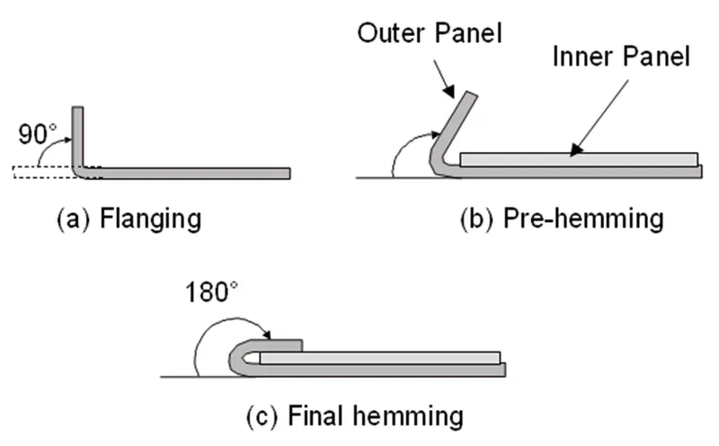
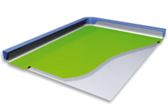
Conventional hemming is shown.
Roll hemming:
Roll hemming is carried out incrementally with a hemming roller. An industrial robot guides the hemming roller and forms the flange. Roll hemming operation can also be divided into several pre-hemming and final hemming process steps. Roll hemming is very flexible to use and tool costs are significantly lower as compared to those of conventional die hemming. However, the cycle times are much higher since the hemming is realized using a hemming roller which follows a defined path.
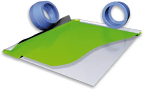
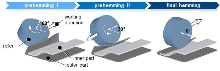
Roll hemming is shown.
Conclusion:
The design and development of backdoor from the given styling surface was carried out, corresponding to the engineering standards, then the draft analysis to check feasibility to manufacture the parts is also done using the ‘NX CAD’ and the detailed report about backdoor and its parts, design parameters, design procedure, analysis and manufacturing techniques is prepared with all the required images.