Design of backdoor
DESIGN OF BACK DOOR
Objective:
- To design the backdoor of a car with the A-surface provided using the proper design methodologies.
- Design the backdoor inner panel with the Hinge,Gas stay, wiper motor,Latch and striker mountings and their reinforcements.
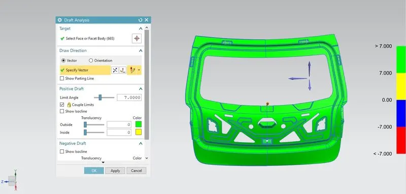
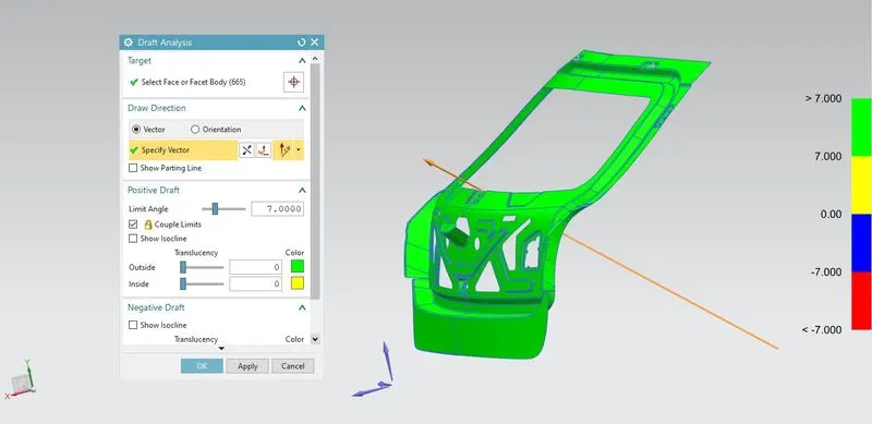
- The inner panel design should be manufacturable by the Deep drawing process in the Tooling direction.
Introduction:
A Backdoor or Tailgate is the door at the rare most end of the car which encloses the boot space. It also has the wiper motor mounted on it, along the Tail lamp, Gas stay, Latch and striker.
The Backdoor is designed to be able to accommodate the various components mounted on it and also affects the rear visibility and boot space.
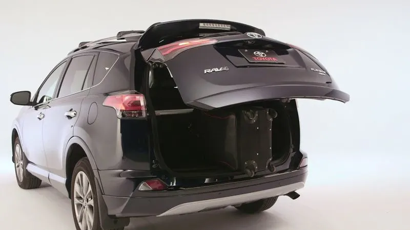
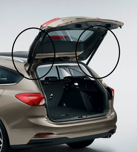
The material used to manufacture a Backdoor varies according to the budget of the project and can be made of plastic, steel or aluminum.
Typical parts of a Backdoor
- Outer panel (upper and lower)
- Inner panel
- Hinge reinforcement (LH and RH)
- Gas stay/ power lifter reinforcement (LH and RH)
- Wiper mounting reinforcements
- Latch and striker mounting reinforcements
Design criteria of a Backdoor
- Rear visibility criteria of regulations
- Boot space
- Rear crash regulation and requirements
- Joining techniques followed such as Hemming, Spot welding etc.
- Manufacturing technique used to create it.
Deep Drawing:
Deep drawing is a sheet metal forming operation in which a sheet metal blank is radially drawn in to a forming die by the mechanical action of punch. It is thus a shape transformation process with material retention.
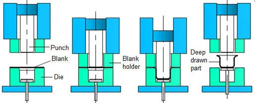
The process is considered deep drawing when the depth of the drawn part exceeds its diameter. This is achieved by redrawing the part through a series of dies. The flange region experiences a radial drawing stress and a tangential compressive stress due to the material retention property. These compressive stresses result in flange wrinkles. Wrinkles can be prevented by using a blank holder, the function of which is to facilitate controlled material flow into the die radius.
Hemming :
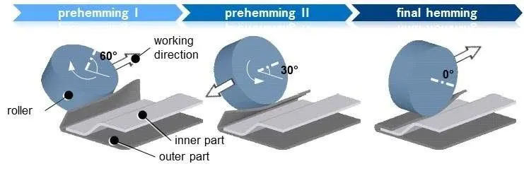
Hemming is a forming operation in which the edges of the sheet are folded or folded over another part in order to achieve a tight fit. Normally hemming operations are used to connect parts together, to improve the appearance of a part and to reinforce part edges.
In a part production, hemming is used in assembly as a secondary operation after deep drawing, trimming and flanging operations to join two sheet metal parts (outer and inner parts) together. Typical parts for thus type of assembly are hoods, doors and fenders.
The accuracy of operation is very important since it affects the appearance of the surface and surface quality. Material deformations, which occur during hemming process can lead to dimensional variations and other defects in parts. Typical hemming defects are splits or wrinkles in the flange, material overlaps in the corner areas or material roll in. This is why it is important to use simulation tools in order to better understand the hemming process and it significantly reduces the number of trail and error loops during tryout and production.
There are various types of hemming processes:
1. Conventional die hemming:
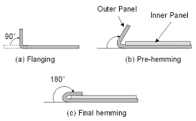
Conventional die hemming is suitable for mass production. In die hemming, the flange is folded over the entire length with a hemming tool. Normally the actual hemming is a result of a forming operation in which the flange is formed with a hemming tool after drawing and trimming operations have been completed. The formed flange is then hemmed in several process steps. These steps involve for example the pre hemming and final hemming depending on the respective opening angle of the flange. Production plants for conventional die hemming are very costly, but cycle times are very low.
2. Roll hemming
Rol hemming is carried out incrementally with a hemming roller. an industrial robot guides the hemming roller and forms the flange. Roll hemming process can also be divided into several pre-hemming and final hemming process steps. Roll hemming is very flexible to use and tool costs are significantly lower as compared to those of conventional die hemming.However, the cycle times are much higher since the hemming is realized using a hemming roller which follows a defined path.
DESIGN OF THE PARTS:
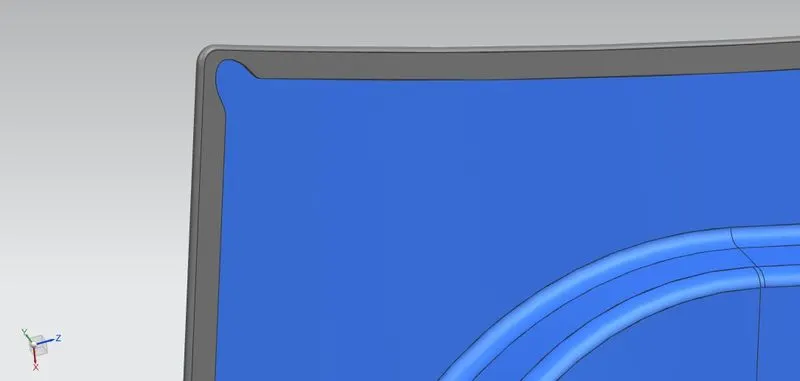
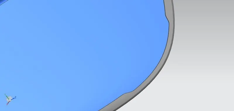
1. Outer Panel (upper and lower):
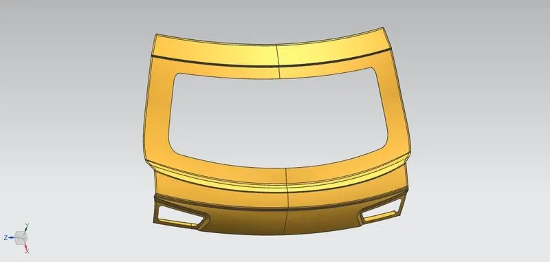
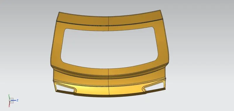
- The upper and lower panels of the outer panel is made out of the styling surface provided and given a thickness of 0.75 mm.
- Hemming is created in these panels by offsetting the surface according to the panel thickness and clearance required between the outer and inner panel for hemming.
- Excess material is removed from the lower surface and the two surfaces are joined by means of swept surfaces which created the hemming.
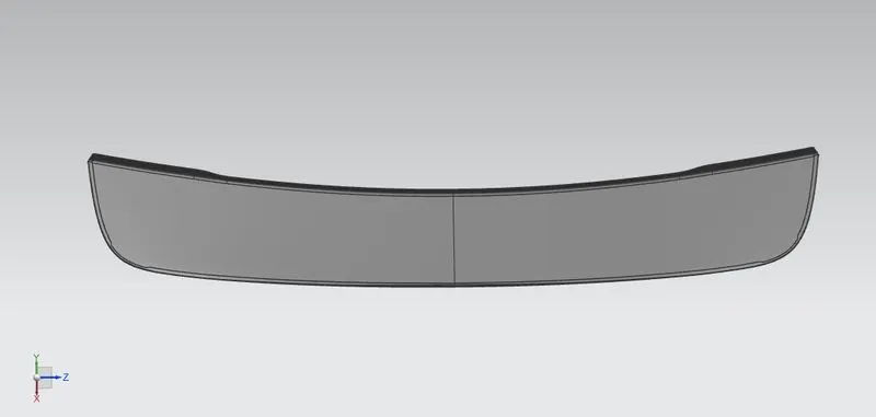
- Corner reliefs are also provided to prevent deformation during hemming process.
Lower panel

Reliefs
2. Inner Panel:
The inner panel is also created from the styling surface provided and the below steps are followed ro design it.
- The tooling direction for the deep drawing process is created first since the design of the inner panel is made with respect to the tooling direction.
- An effective sealing flange is created and the inner panel shape is designed along with it.
- A flange is created for mastics, the flange attaches the inner and outer panel by means of mastics and thus it is at a 5 mm distance from the outer panel.
- A hole is provided for the tail lap wiring and harness.
- Embosses in the shape of 'v' or 'Y' is created, the shape of the embosses help dissipate the force which would be applied to the Tailgate in case of a collision.
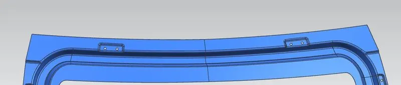
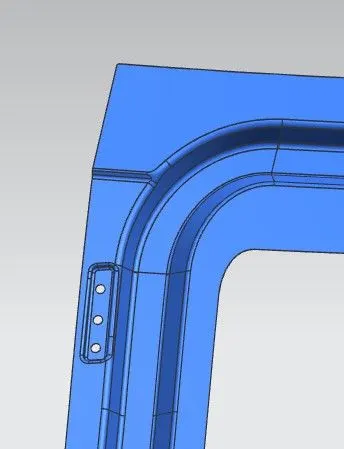
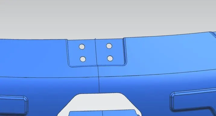
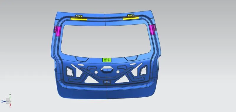
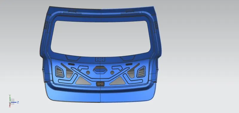
- The hinge,gas stay, wiper and latch and striker mountings are created.
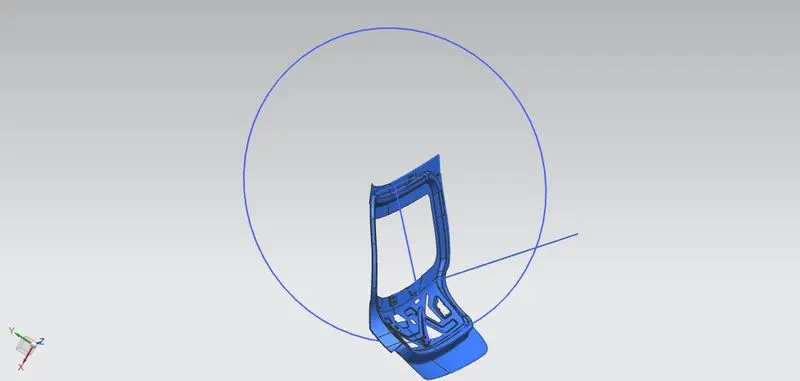
- For the latch and striker mounting position a Backdoor trajectory is created from the hinge axis, this shows the path followed by the backdoor when opening or closing. The mounting of the latch has to be perpendicular to this hinge axis for the back door to open and close properly.
- Th inner panel is also provided with a thickness of 0.75 mm.
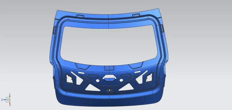
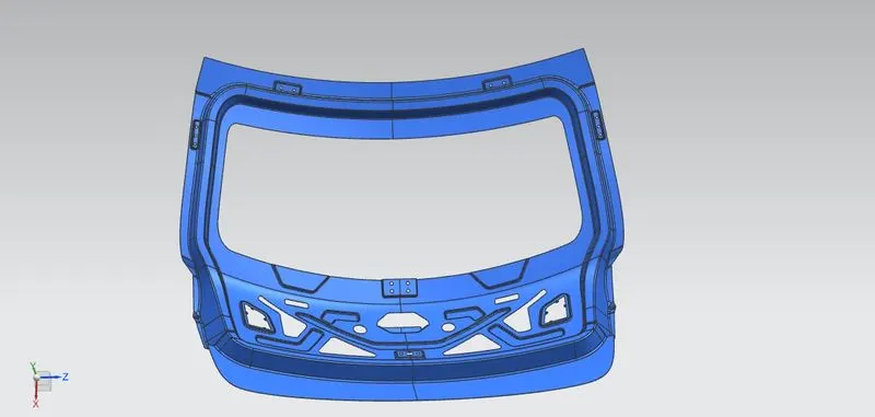
Hinge mounting Position
Gas stay mounting position
Wiper mounting position
Hood trajectory
Latch and Striker Mounting position
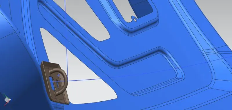
3. Reinforcements:
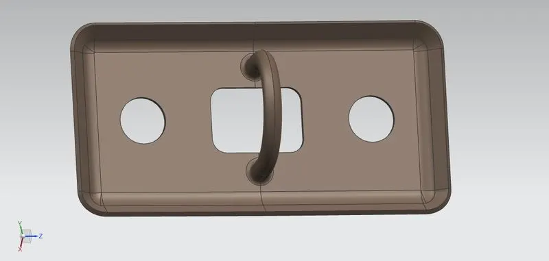
- Reinforcements for the hinge,gas stay, wiper, latch and striker mounting are created since these parts of the inner panel would be subjected to load thus making the areas susceptible to damage. Reinforcements are added to compensate for the weaker regions.
- These are created by extracting the inner panel geometry and cutting out the required portion from it for the reinforcements.
- The thickness provided for each reinforcement is 1.5mm.
hinge Reinforcement
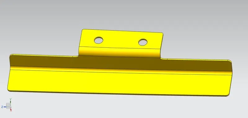
gas stay
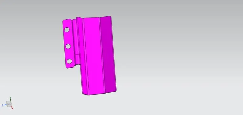
wiper motor
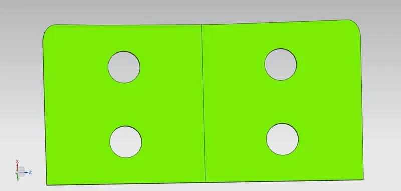
Latch and Striker Reinforcement
Draft Analysis
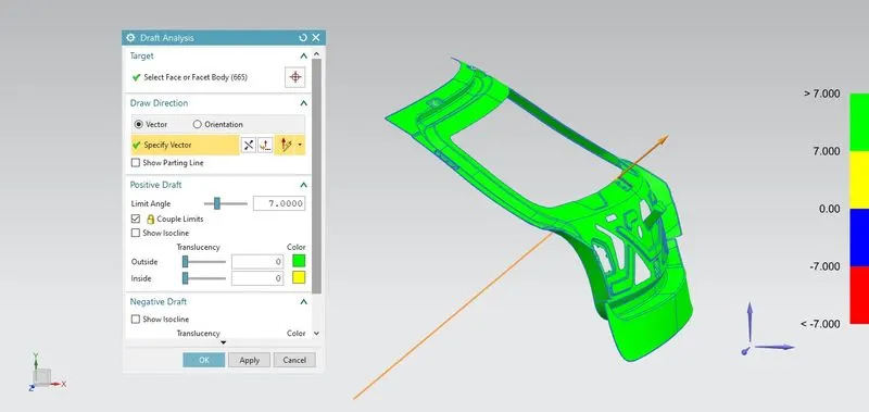
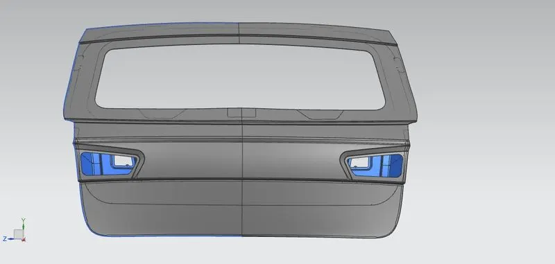
Views of back Door
CONCLUSION :
The Backdoor is designed successfully with the required mountings and reinforcements. Draft analysis is also performed and the parts are found to be manufacturable by deep drawing process.