Design of backdoor
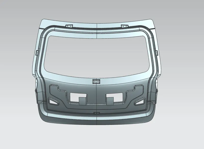
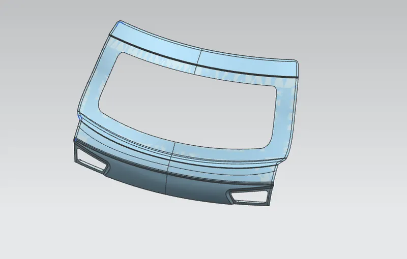
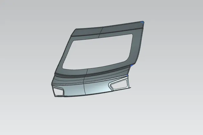
It consists for outer panel, inner panel, hinge reinforcements , gas stay reinforcements , wiper motor reinforcement, latch reinforcement
both aluminium and steel used to manufacture the back door , most of parts create by aluminium
PARTS:-
outer panel:
it is the styling surface of back door
it is the source of designig the other parts
its the outer cover of back side of car
inner panel:
it also provide the strength of outer panel
inner panel has reinforcements and embosses to stregthening
gas stay , hinge , latch , wiper motor reinforcements are connected ti the inner panel
hinge reinforcements :
its enable the opening and closing of the back door
hinge fixed on the back door and other end of roof panel
its used to aline the latch and trajectory of back door opening and closing
gas stay reinforcement:
gas stay device used to support the back doorin its open position
gas stay in engaged position into support position automatically open s the bck door
latch reinforcemeent:
its used to lock the back door with car
wiper motor reinforcement:
lts used to strengthening the back door
PROCEDURE:-
INNER PANEL:
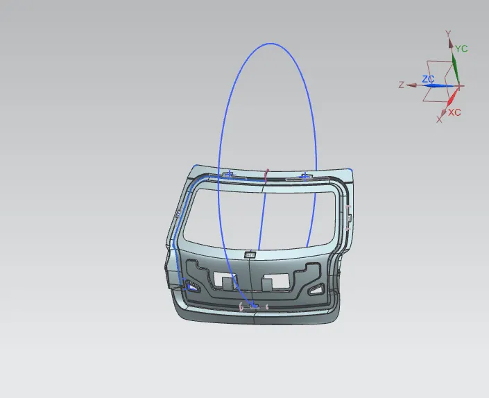
open the given bac door model in the nx cad
extract the given surface in to 2 parts
one surface makes in the part folders a name outer panel upper
and other surface makes in the part folder as name outer panel lower
make other 2 part files as empty as the name of hinge reinforcement LH na RH
make 2 part files as empty as the name of gas_stay reinforcement LH na RH
make part file as empty as thr name wiper motor reinforcement
make part file as empty as thr name latch reinforcement
make the another part file as in extract the given surface in to 2 parts , as name innr panel
all prt files are in the back doof assembly
the 2 surfaces are enter in to the inner part file as usinng wave geometry linker
and make the features group for linke faces as name refferene geometry
then make the tooling direction by using intersectline in the maked 2 lines as outer side
extrect the outwr panel ones and make feature group as working surface
offset the faces at 1.7mm distace
make line by using offset line in face
bride curves used to connect lines
trim the extra side of sheet by using trim sheet
untrim the back tail of outer surface and make lines by using offset in face at correct valve
trim the the extra portions
bride curve used to connect both surface and make surface by using throughcuve mesh
offset the suface at required length
make linke by using offset in surface
trim the sheet at required length
bridge curve used to connect both surface and make surface between them
sew all sutfaces
extracted the sew surface
law extend the surfce at given distance at angle of tooling direction
extract the law extruded surface and apply the face blend
extract the upper and lower outer panel
trim and extend used to make 2 surfaces trim perfectly
connect 2 surfaces by using bridge curve and makes surfaces between them
connect 2 surfaces by using bridge curve and makes surfaces by using studio surface
apply trim sheet to trim extra surface
sew all surfaces and apply edge blend
then extract the surface
then apply face blend in 2 adjesent sides
make features group as connecting blends1
extract he blended surface and then extend the sheet
apply low extension at ends in the tooling direction
trim the upper sides properlly and trim top surface properlly
then low extend same way of above create surface
make line properly to cut the surface
then make the bridge curve to make the between surface correctly by using studio surface
make top surface by using bridge curve and studio surface at the bottom side of panel
then extend the sheet and trim all extra portions
apply face blend on the edege
extract the body ones
make another feature group aas wind sheild
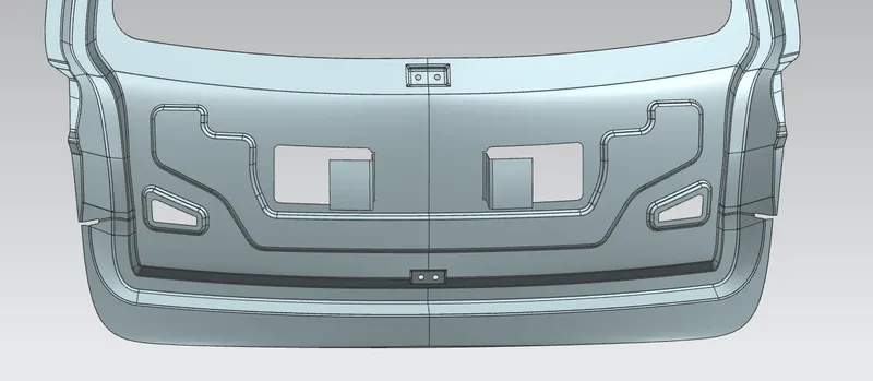
make sketch for tail tailight ebmoss
ebosses the sketch upward upto 10mm
apply blends on the edges
make offset line in top surface and trim it
make sketch for tail y shape ebmoss
ebosses the sketch upward upto 10mm
apply blends on the edges
make a plane for hinge reinforcement
make line at an angle then low extrude the surface at required length
law extrude 4 sides upward an sew all makes surfaces
trim and extend used to make emboss structure
edge blend apply on the all edges
make hole at centreby using trim sheet
make a plane for gas_stay reinforcement
make line at an angle then low extrude the surface at required length
law extrude 4 sides upward an sew all makes surfaces
trim and extend used to make emboss structure
edge blend apply on the all edges
make hole at centreby using trim sheet
make sketch on the wiper_motor reinforcement
emboss create at 10mm distance
edge blend apply on the all edges
make hole at centre by using trim sheet
extend all sides at 10mm and trim by mirroring plane
sew all surfaces as sheet
mirror the sew surface by using x-y plane as mid plane
make the mid piont of LH and RH and connects to make a line
make a plne at the cente of line and make a cricle at center of line
make a plane for yatch reinforcement
make line at an angle then low extrude the surface at required length
law extrude 4 sides upward an sew all makes surfaces
trim and extend used to make emboss structure
edge blend apply on the all edges
make hole at centre by using trim sheet
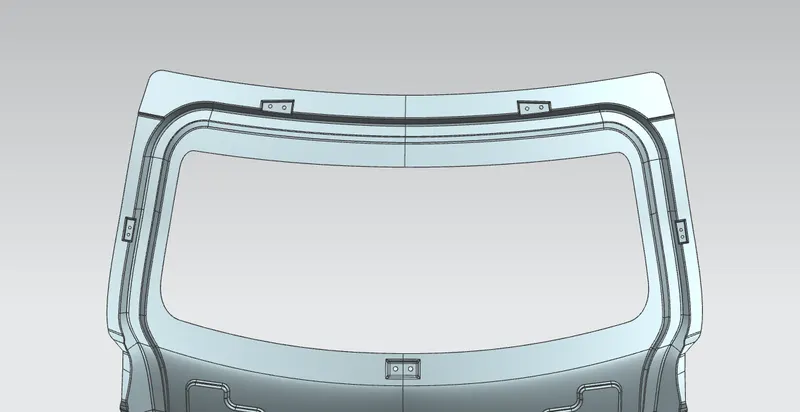
thicken the inner pane1 at 0.75 in upward direction
OUTER PANEL UPPER:
offsed the surface at 2.65mm in down ward direction
make a offset line upto 12 mm and trim the inner side portion
at the corner make a sketch by using curve on surface
trim the surface at u shape
make bride curve on the both sides by using 2 surfaces edges
swept commad used to make the corner surface
when the side of not showing proper swept , then cut smaller portion of swept surface and make a new stutio surface bridge curve
sew all surfaces
extend the outer side of all surface and trim at refference of mirroring plane
mirror all surface at x-y plane refference plane
sew all surfaces ones
thicken the sew sufaces at 0.75mm downward direction
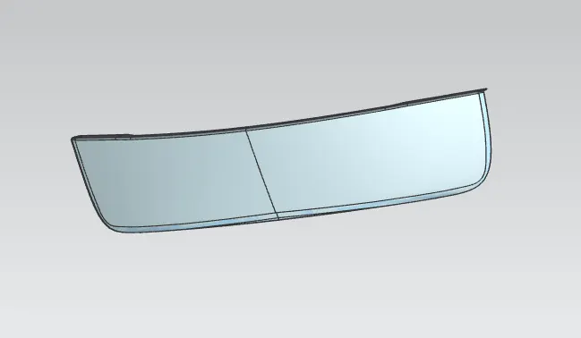
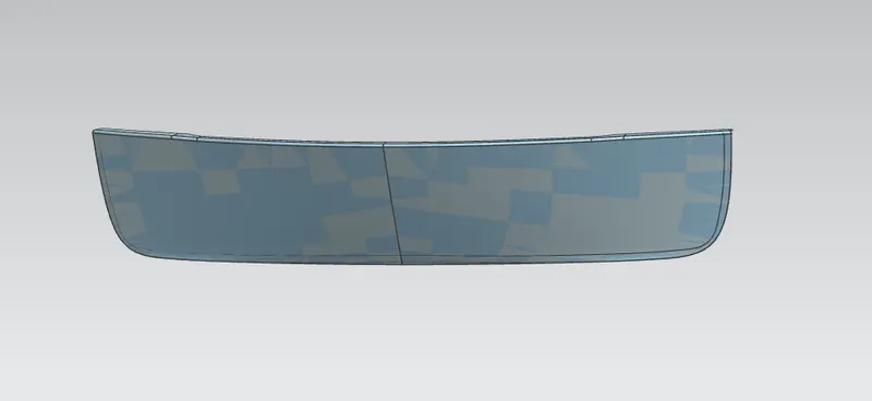
OUTER_PANEL_LOWER :
offsed the surface at 2.65mm in down ward direction
make a offset line upto 12 mm and trim the inner side portion
at the corner make a sketch by using curve on surface
trim the surface at u shape
make bride curve by using 2 surfaces edges
swept commad used to make the corner surface
sew all surfaces
extend the outer side of all surface and trim at refference of mirroring plane
mirror all surface at x-y plane refference plane
sew all surfaces ones
thicken the sew sufaces at 0.75mm downward direction
HINGE_REINFORCEMENT_LH :
wave geometry linker command used to extract needed face from innel panel
make a line at required length by using datum plane and and inter section curve
trim the surface at maked line
thicken the surface at 1.5mm thicknes
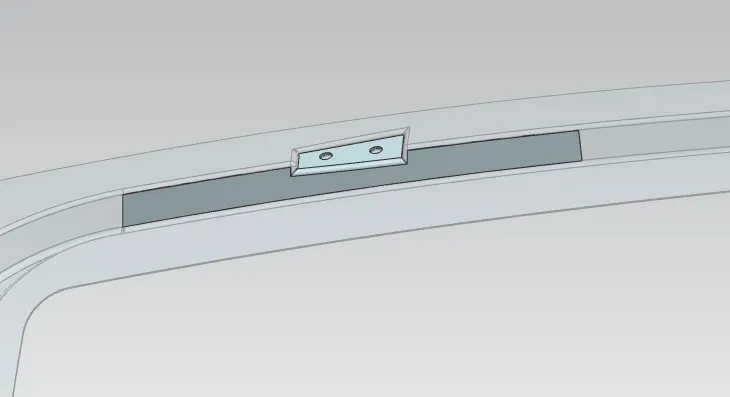
HINGE_REINFORCEMENT_RH :
wave geometry linker command used to extract needed face from innel panel
make a line at required length by using datum plane and and inter section curve
trim the surface at maked line
thicken the surface at 1.5mm thicknes
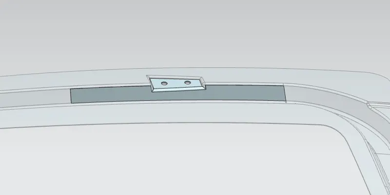
GAS_STAY_REINFORCEMENT_LH :
wave geometry linker command used to extract needed face from innel panel
make a line at required length by using datum plane and and inter section curve
trim the surface at maked line
thicken the surface at 1.5mm thicknes
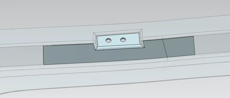
GAS_STAY_REINFORCEMENT_RH :
wave geometry linker command used to extract needed face from innel panel
make a line at required length by using datum plane and and inter section curve
trim the surface at maked line
thicken the surface at 1.5mm thicknes
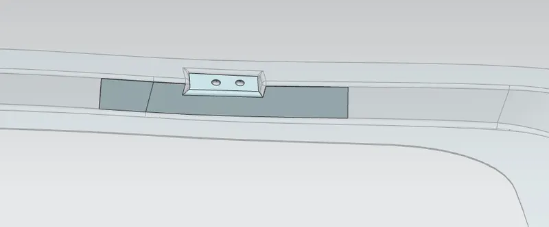
WIPER_MOTOR_REINFORCEMENT :
wave geometry linker command used to extract needed face from innel panel
thicken the surface at 1.5mm thicknes
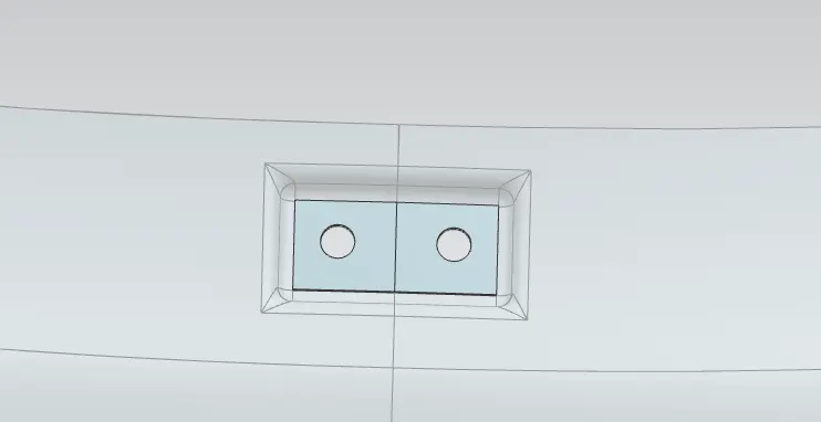
LATCH_REINFORCEMENT :
wave geometry linker command used to extract needed face from innel panel
make a line at required length by using datum plane and and inter section curve
trim the surface at maked line
thicken the surface at 1.5mm thicknes
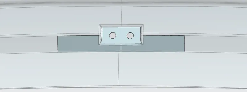
DEAFT ANALYSIS :
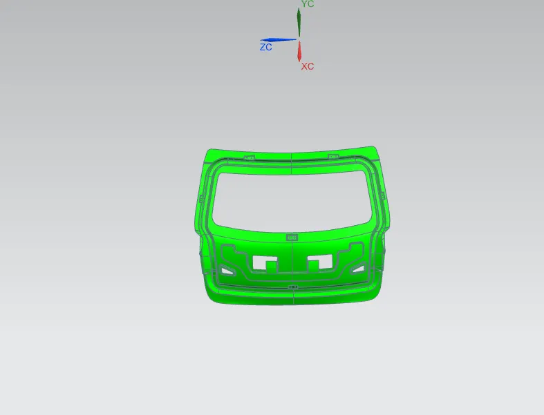
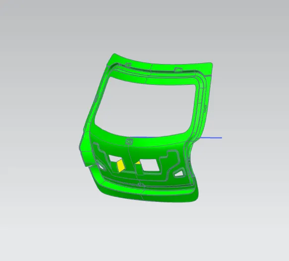
its openation used to help for checking the product will be easily revomed from the tool
when design the product then need to be angled slightly so that the tool can be pulled away from object easily without deforming , this angle is called draft angle
ASSEMBLY MODEL:
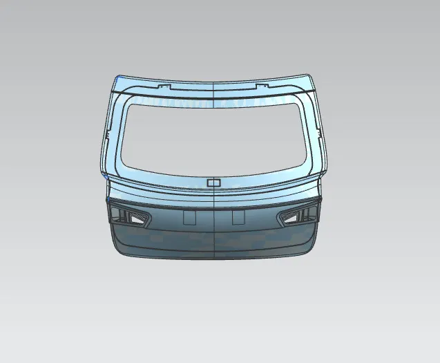
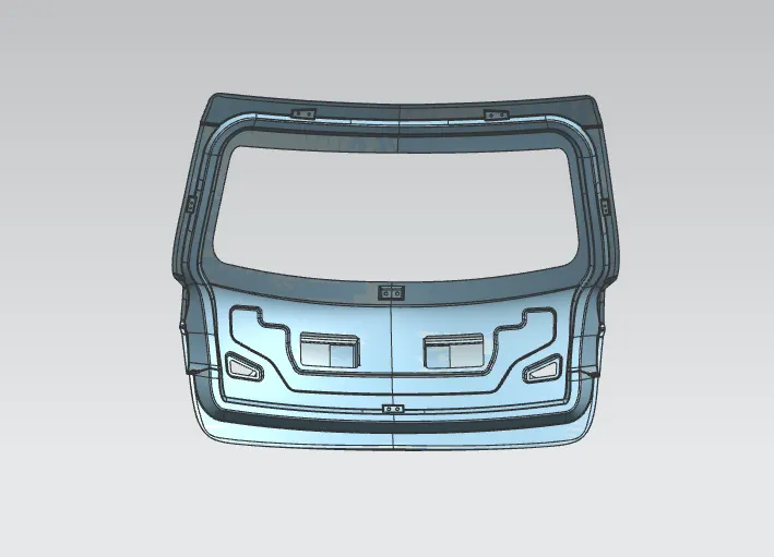
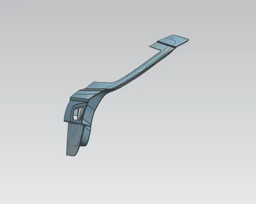
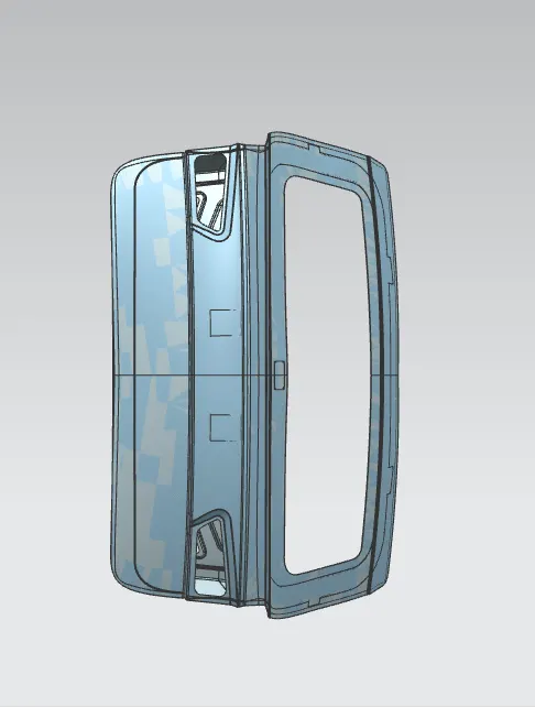
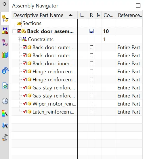
google drive link:--
https://drive.google.com/file/d/1Ju0a9w0R9UauFHYM8TIIb2pKdawhqtwq/view?usp=sharing
CONCLUSION:
the back door is designed from the given styling surface with necesary reinforcement and emboss