Design of backdoor
CAR BACK DOOR(TAIL GATE) DESIGN AND DEVELOPMENT PROCESS.
AIM: To Design a back door of a car using of class "A" surface.
Abstract : A backdoor of a car also known as tail gate is a commodity which normally serves the purpose of covering the car from the rear end. But there are more function that come with it which has to be considered while making a design of the same like rear visibility criteria and boot space.This part is usually designed keeping the master section of the rear roof rail because of the sealant flanges and also various other consideration, as it contact with the side body of car.
Theory : Majorly there are three type of mountings back door. Which names are given below.
- Top mounted
- Side mounted
- Bottom mounted
Basically this mountings will help us to determine the were the latch position will be. Based on this we position the latch. As below fig shown type of mountings.
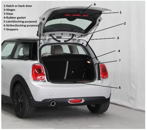
Fig 1.1 Top mounted type back door.
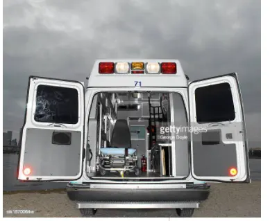
Fig 1.2 Side mounted type back door.
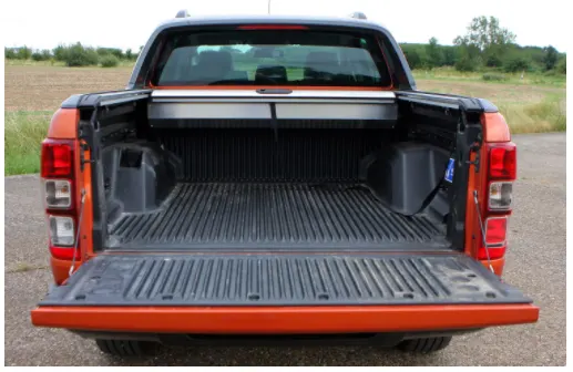
Fig 1.3 Bottom mounted type back door.
Now designing the top mounted type hatchback back door of car.
Before Design process we know about the all parts of back door for design consideration.
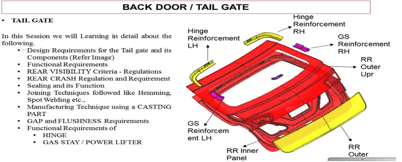
Fig 1.4 Parts and Design consederations.
The above fig cleaes that all parts and design concepts as well manufacturing process.
Now first start with design. Below listed the all parts names of back door assembly.
- Outer panel upper & lower.
- Inner panel
- Hinge Reinforcement
- Gas stay Reinforcement
- Latch Reinforcement
- Wiper Motor Reinforcement
1.Outer panel upper & lower are the styling surfaces. First we check this styling surface having any irregularities in the surfaces and repair it if required.
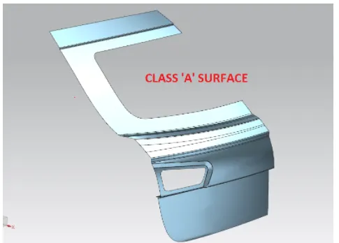
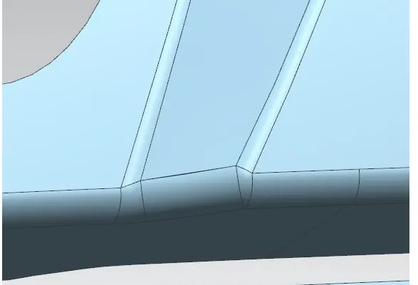
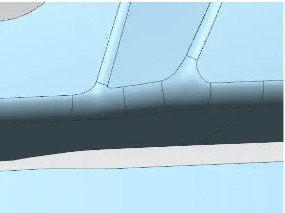
Fig 1.5 Class A Surface. Fig 1.5a Surface having an irregularities. Fig 1.5b Repaired Surface.
As above fig shown class A surface which having an irregularities sufaces. The irregularities surfaces are repaired according to requirements.
2. Inner Panel : While developing the inner pannel we first start with the sealing flange preparation. As shown below fig 1.6.
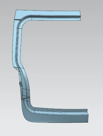
Fig 1.6 Sealing Flange.
For creating the sealing flange we take referance from the roof master section. But in this condition data was not available hence sealing flange was created by same basic referances.The space occupied by the rubber sealent is up to in the range of 15mm-25mm. In the open condition it was 25mm so we maintained that distance between inner panel and the sealing flange. Once this flange is made, we make a connecting flange on both sides of it and complete this flange to be joined with inner panel.
The shape of the inner panel is same as that of the outer panel up to the windshield suface. After that we have to make space for various components such as latch,hinge mountings,gas stay mounting and wiper moter etc. So we make a proper curved surface at the lower side so that we avoid kinks at the mirroring plane. Once the main body is ready, we have to decide the design of the following things.
- Mastic region: Whether we have to design it as a big one at a single region in the centre or two small regions.
- Emboss : We have to create proper emboss either Y or V and combination of both to diverge the force.
- Material cut-outs : Due to ample space, we should remove the material from few regions to reduce weight of the inner panel.
There are few mountings which we have to keep consideration while creating reinforcements.
- Hinges : Inner panel hinges are made such that the back door will be mounted on the roof, so the hinges mounting emboss has to be provided accordingly on the top of iner panel.
- Gas stay : The backdoor will have used the gas stays for reduce the effort of opeing and closing. In same time used power gas stays which having an self opeing and closing. For this have to give the embosses for mountings. Emboss is given for both side as LH & RH.
- Wiper Motor : Wiper motor emboss will given centre of the windshield area.
- Latch : The operation of latch is to be lock and unlock of the back door. For this also given embosse while considering the opeining and closing trajectory.
Mastic Region
Inner and outer panel is joined by using heming process but to make bound stronger we introduce mastics for that we creates mounting suface in inner panel. The mastics having an dia up to 80mm and thickness up to 4mm to 5mm. Thus we must having a structure which is projected from the inner panel towards the outer panel his must be around 5mm away from the outer panel serve its purpose.
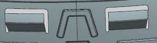
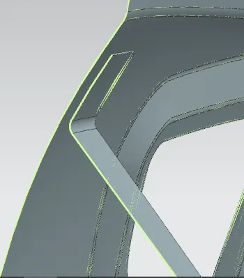
Fig 1.7 Mastic Flange and Gap between Outer and Inner panel.
Emboss : This feature helps to increase the strength in the component as well as changes the direction of the forceses. Mainly save parent parts from damages. The deep of emboss mainly on elongaton of material. While making emboss take care of draft angle also. Type of emboss are Y or V maily used. The emboss punching direction is follow tolling direction.
below fig 1.8.
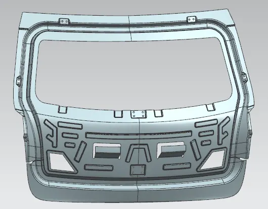
Fig 1.8 Inner Panel back door Emboss.
HINGE,GAS STAY,LATCH &WIPER MOTOR MOUNTINGS.
Hige Mounting : These are 2 hinges LH & RH. The back door compeletly mounting on this hinges as below fig 1.9 shown.
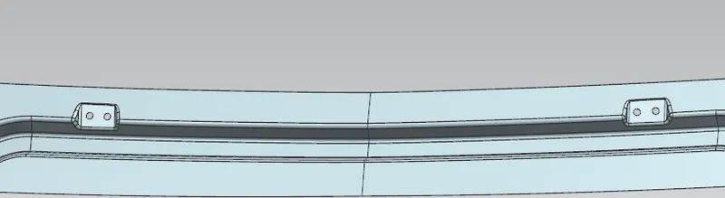
Fig 1.9 Hinge Mountings.
Gas Stay Mounting : This are helps eassly opeining and closing. Below fig 1.10 shown.

Fig 1.10 Gas Stay Mounting.
Wiper Motor Mounting : This mounting will helps to mounting of wiper motor. Below fig 1.11 shown.
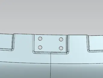
Fig 1.11 Wiper Motor Mounting.
Latch Mounting & Trajectory : The position of latch is depends on trajectory. Opening and closing of latch is follow the trajectory. Below fig shown 1.12 & 1.13.
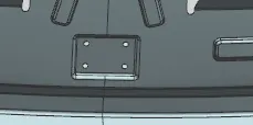
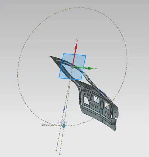
Fig 1.12 Latch Mounting Fig 1.13 Latch Trajectory.
Reinforcements
Hinge Mounting Reinforcements.
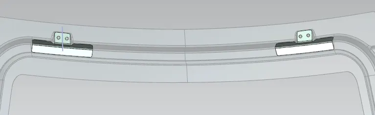
Fig 1.14
Gas Stay Mounting Reinforcements.
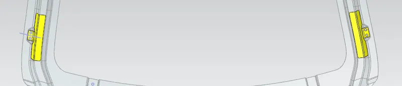
Fig 1.15
Wiper Motor Mounting Reinforcements.
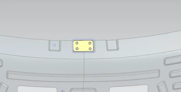
Fig 1.16
Latch Mounting Reinforcements.
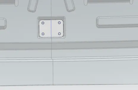
Fig 1.17.
Draft Analysis.
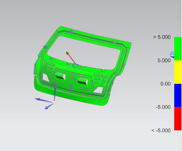
Fig 1.18 Draft Analysis
Tooling Direction.
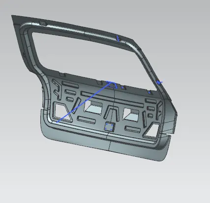
Fig 1.19 Tooling Direction.
Thickness.
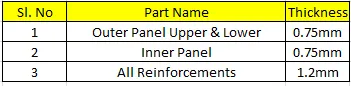
Manufacturing or Part Development Process.
Benchmarking Process.
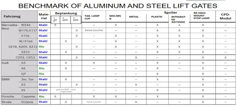
Fig 1.20 Benchmarking Sheet.
Manufacturing Process.
1 Deep Drawing : The deep drawing process is an effective method of manufacturing of cups, cans and other similar deep drawing products. The deep drawings having 2 main steps.
- First-Stage Drawing : The blank shape of metal is placed on the die and contact with the punch. when the metal specimen is flat piece of sheet metal used in forming and finish the product. initially the punch moves in downward direction. The outer rim of blank is subjected to pure radial drawing(drawing toward in vertical axes) between die and blank metal. The metal become a bend and sliding overe die and also stretched between die and punch. The metal in vicinity of punch head and contact with it bend and side over radi and stretch overe punch head.
- Redrawing : The components drawn from first stage again it is redrawn convert in to more depth to from a cup shape in the die and punch. The second stage of drawing is called redrawing.
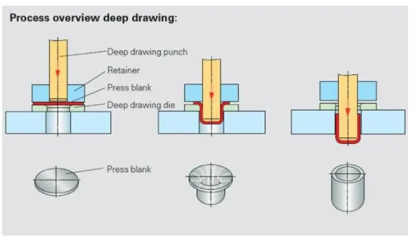
Fig 1.21 Deep Drawing
Embossing : Is a metal forming process for producing raised or sunken designs or relief in sheet materials by means of matched male and female roller dies, theoretically with no change in metal thicknessor by-passing sheet or a strip of metal between rolls of the desired pattern. Metal sheet is drawin through the male and female roller dies producing a pattern or design on the metal sheet. Depending on the roller dies used, different patterns can be produced on the metal sheet.
Material commonly used in the metal enbossing process include.
- Aluminm Alloys.
- Steel Alloys.
- Zinc.
- Copper.
- Galvanized Steel.
- Brass.
- Cold rolled Steel.
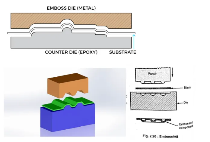
Fig 1.22 Embossing
Hemming : Is a forming operation in which the edges of the sheet are folded over or foldded over another part in order to achive a tight fit.
Normally hemming operations are used to connect parts togethe,to improve the apperarance of a part and to reinforce part edges.
In car part production, hemming is used in assembly as a secondary operation after deep drawing, trimming and flanging operation to join two sheet metal parts(outer and inner) together. Typical parts for this type of assembly are hoods, doors, trunk lids and fenders.
These are various type of hemming operations.
- Conventional die hemming : In conventional die hemming, the flange is foldedovere the entire length with a hemming tool.
- Roll hemming : In roll hemming, the hemming roller is guided by an industrial robort to from the flange.
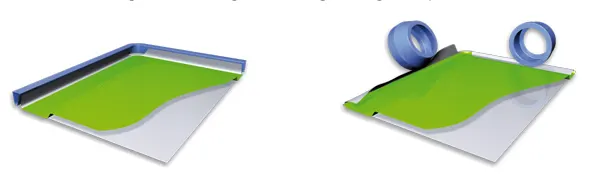
Fig 1.23 Hemming process.
Open Hem : A hem has a full round feature and a return flange. In open hem bend angle is equal to 180 degrees.
Tear deop Hem : In tear drop hem the bend angle is greater than 150 degrees.
Closed Hem : Hemswithout any inside radius are called as closed as closed hem.Closed hems ae nor recommended if the hem geometry is to be painted or if the material used is SST or Aluminium.
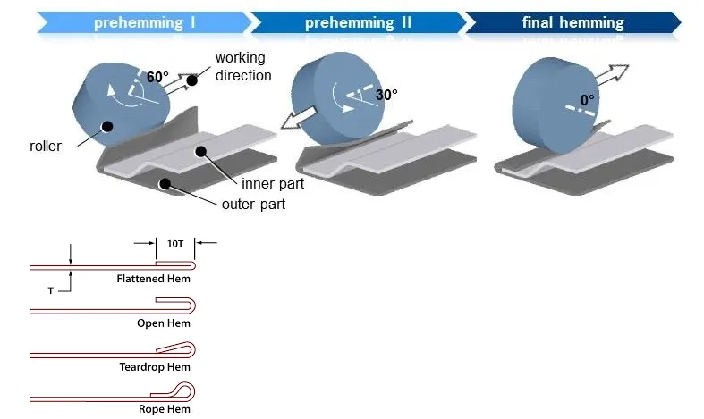
Fig 1.24
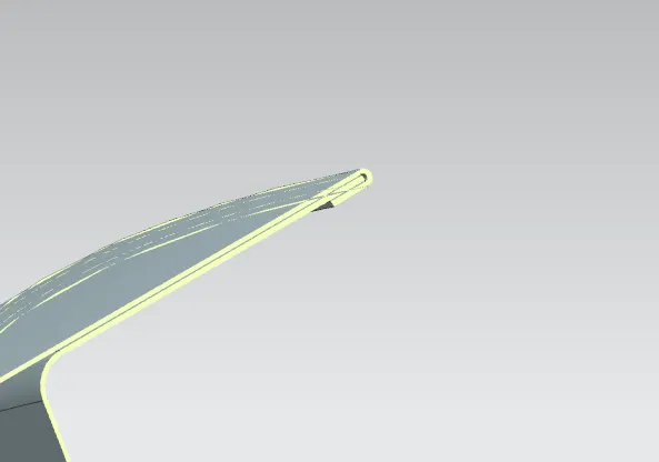
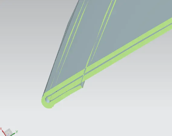
Fig 1.25 Designed part Hemming did.
Hemming Reliefs.
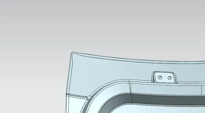
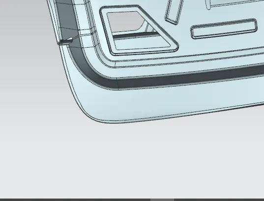
Fig1.26 Hemming Reliefs.
Blanking : Is a cutting operation of a flat metal sheet and the article punched out is known as blank. Blanks is the requried product of the operation and the metal left behind is considered as waste.
Punching : It is similar to blanking only the main differance is that, the hole is the requried product and the material punched out from the hole is considered as waste or scrap.
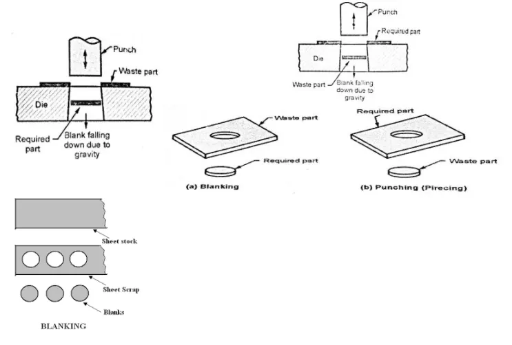
Fig 1.27 Blanking & Punching.
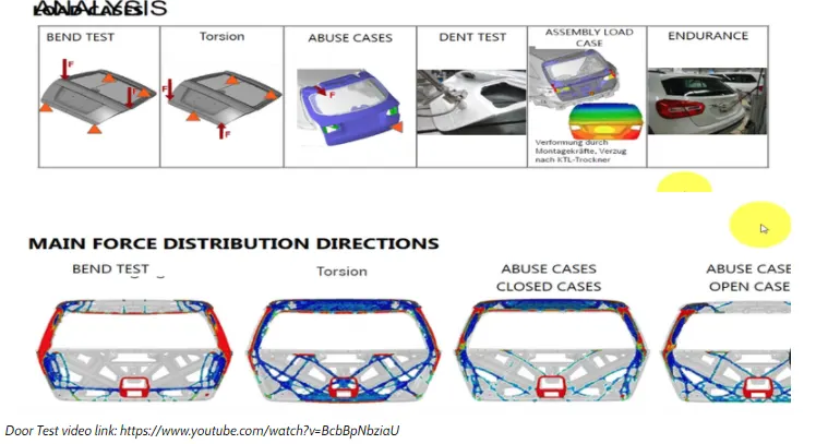
Fig 1.28 Part Analysis.
Conclusion : A back door design and manufactiring techniques are used as per OEM Standards.