Design of backdoor
BACK DOOR DESIGN
Introduction :
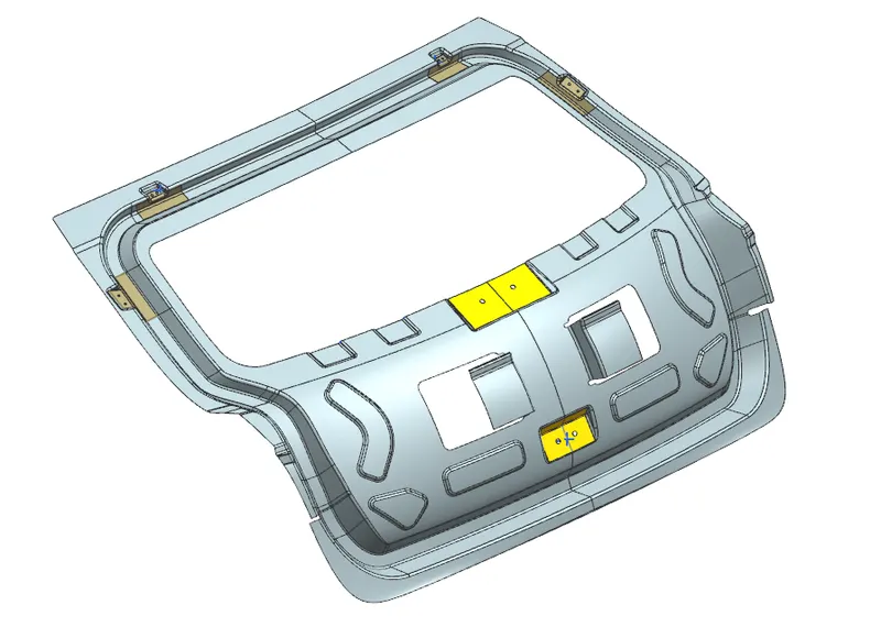
The backdoor design involves the development of sealing flange, hinge reinforcement, gas stay reinforcement, wiper motor reinforcement,latch and striker reinforcement. Just like hood this also consists of inner and outer panels which will be joined by a hem joint. And also mastics are applied in the middle of the door to hold them together. By making the assembly thinner it is possible to increase the luggage area and another important criteria is the rear visibility though the glass.
The inner panel can be made out of either steel or aluminium. The whole inner panel can be cast as a single part and aslo the weight will be drastically reduced in case of aluminium panel. The number of components is increased as well as the weight when the steel part is used for inner panel.But aluminium is highly expensive when compared with the steel and the industry when it comes to mass production prefers to use steel to make cost effiecient cars.
There are two cases in which the hinge can be mounted ,
- Hinge inside backdoor
- Hinge outside backdoor
Based on this, the position of gas stay mounting and power spindle will also vary.
When there is a crash the most affected area will be the lower part and hence in order to distribute the energy outside from the passenger cabin, we must in corporate y embosses that will direct the forces outside.
And also sufficient material removal is necessary to keep the C.G of the assembly in good condition. There should be proper access cut outs for certain mountings like wiper motor to avoid complexity.
The major tests which will be done on the back door involves,
1) Bend test
2) Torsion test
3) Abuse cases
4) Assembly load
5) Dent test
6) Endurance
Development of Inner panel
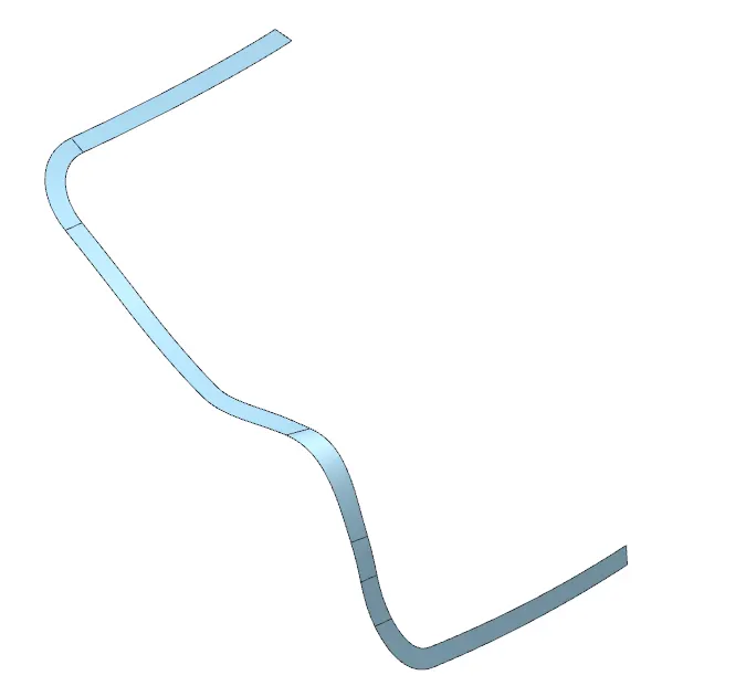
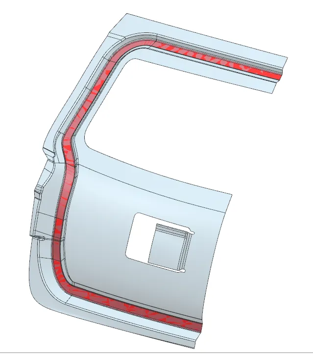
- Development of sealing flange :
Purpose of sealing flange is to stop the water from entering inside the car cabin. A thick rubber bead like material is placed on the space provided for sealing flange.
2. Joining upper and lower panel :
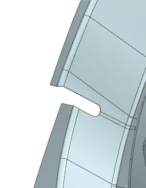
A relief is provided at the joining where top and lower inner panel are connected.

3. Development of inner panel and outer panel mastic area :
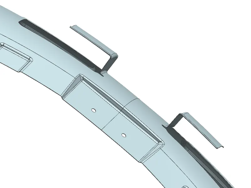
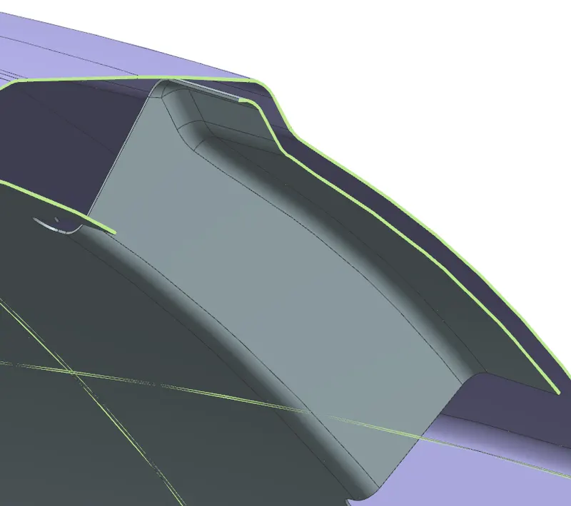
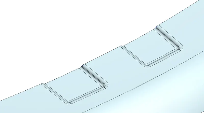
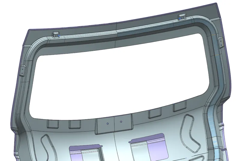
Other than the hemming provided for joining the inner and outer panel, a flange is bent from the inner panel and extended as a mastic area. Mastic is applied on this region which joins the inner and outer panel. Embosses are given right below the rear glass as well for the mastic application.
4. Development of hinge and gas stay emboss/reinforcements :
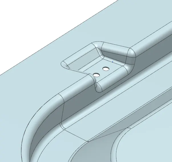
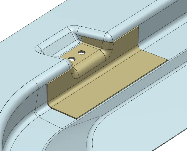
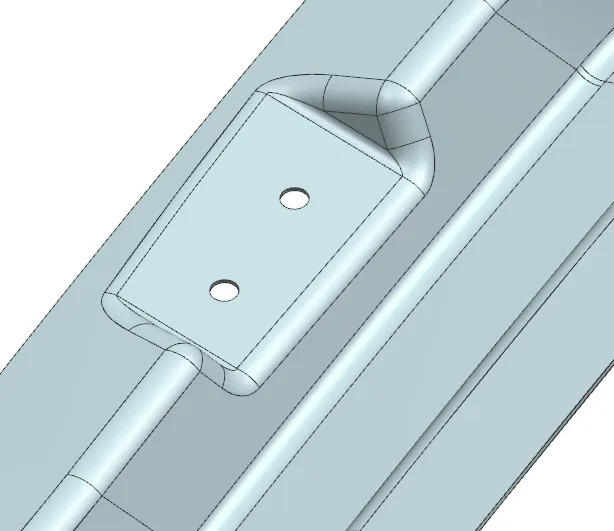
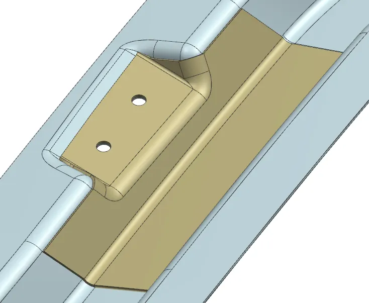
For the hinge and gas stay mounting when it is directly mounted on the inner panel the strength is reduced locally on that area. So the emboss is always a preffered choice for the mountings to improve the strength locally. By adding reinforcements on the area the compromised strength is improved. A thickness of 1mm is given for the reinforcements.
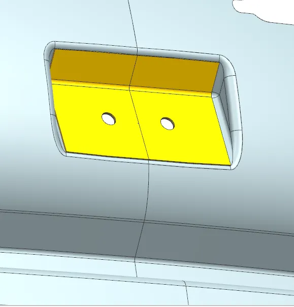
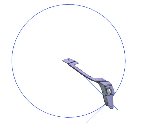
5. Development of Latch emboss/reinforcements and functional circle verification :
The placement of latch should be made considering the functional circle which will ensure that latch and striker gets engaged properly. Based on the this we should adjust the emboss placement and latch reinforcement.
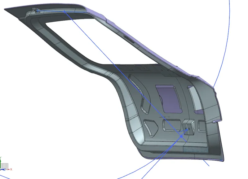
6. Wiper motor emboss and reinforcement :
The Wiper motor is placed right below the rear glass. In order to provide easy access while mounting the motor, the emboss is made open on one side.
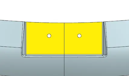
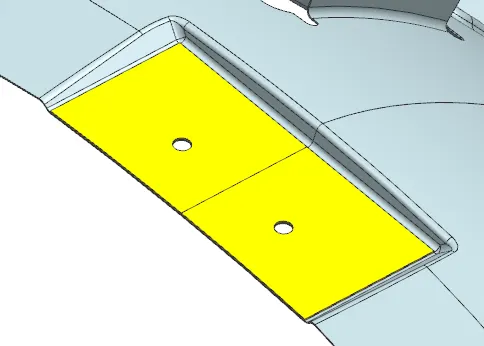
7. Strengthening embosses on the Inner panel :
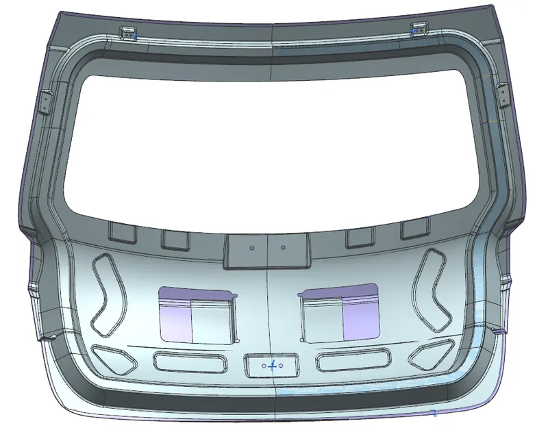
It is important to design these embosses in a v or y direction which will direct the forces outwards the cabin when met with collision from the rear.
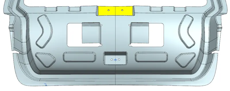
Development of Outer panel Hemming
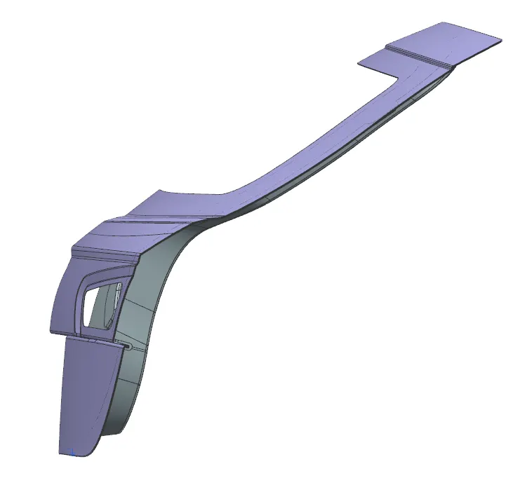
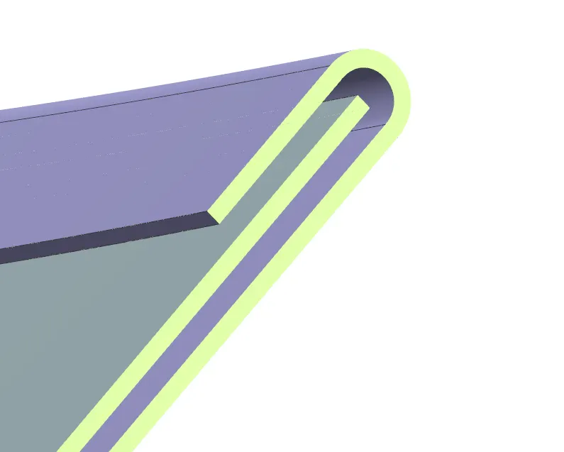
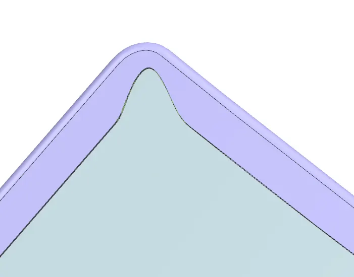
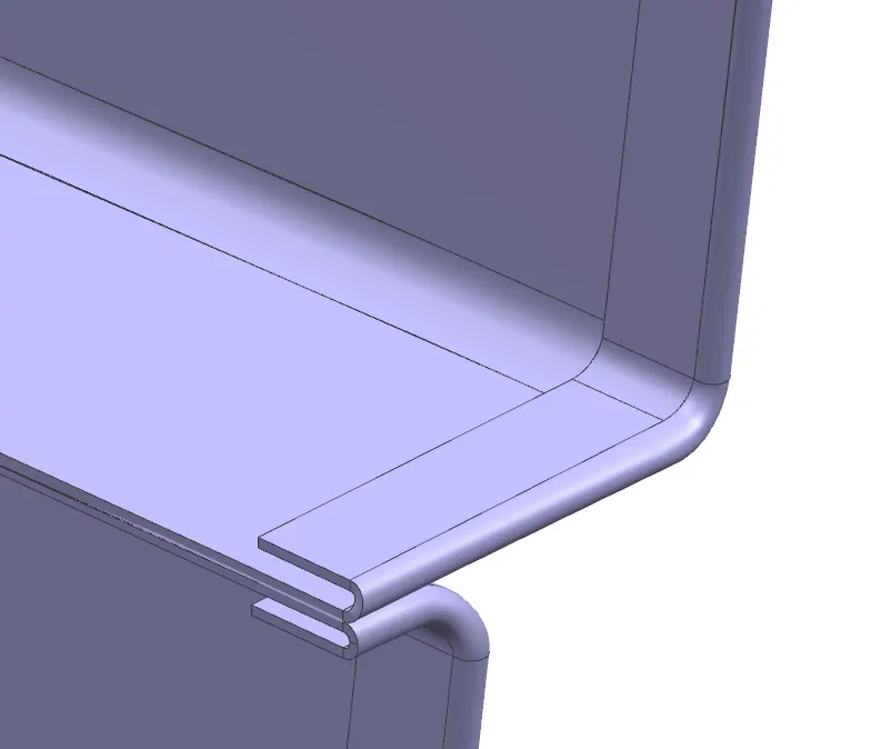
The outer panel hemming is made by extending the class A skin and proper relief is provided on the corners to ensure easy rolling while hem is made.
Minimum gap of 0.2mm is maintained with the inner panel on top and bottom.
Outer panel upper and lower joining :
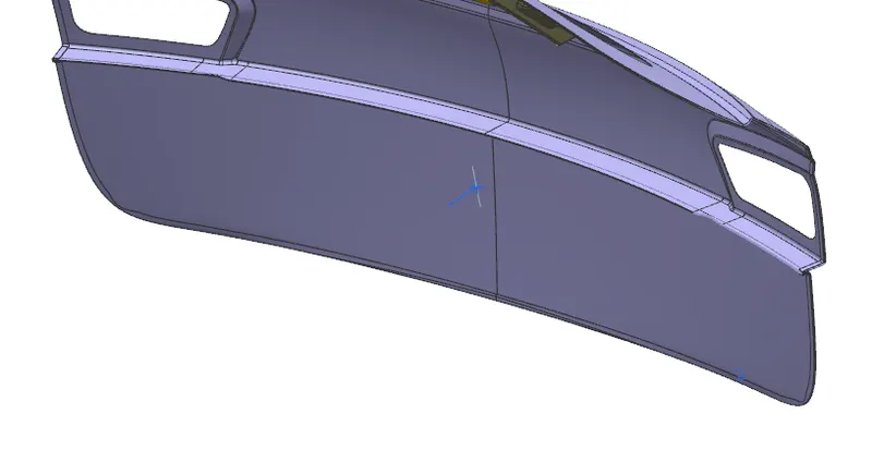
The outer panel upper and lower is joined by the inside flange which are spot welded together.
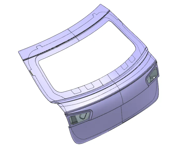
Various views of the backdoor assembly :