Design of backdoor
Introduction :
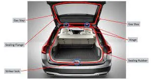
Back Door or Tail Gate is the part which covers the rear end or back portion of the car.Back door can be placed in such a way to open upwards, Downwards or from the side. It helps in accesing the luggage compartment or back seats in lengthier cars. Back door is attached with the help of the hinges and supported by the gas stay unit. opening of back door can be acheived by Gas stay operation or with electrical power spindles to access the opening and closing with minimum efforts.
Materials Used :
- Aluminium -Made with Casting Process - Non uniform Thickness can be acheived and no reinforcements required seperately and less in weigth.
- Steel - made with Deep Drawing ,stamping or Lancing , uniform thickness so additional reinforcements is necessary.
Design Considerations:
- Rear Visibility Creteria
- Boot Spaces and luggage assesability
- Fits and Clearance
- Hinge and Gas stay placement
- Mounts for Wiper motor, lamps and number plate placement
- Crash Requirements
- Sealing creteria to resist vibrations
Types of opening method:
- Upward opening
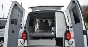
- Sideway opening
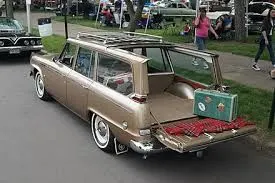
- Downward opening
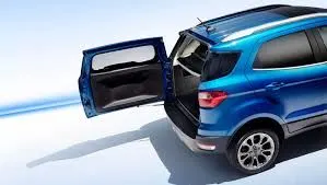
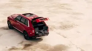
Sample Images for Back Door of Cars :

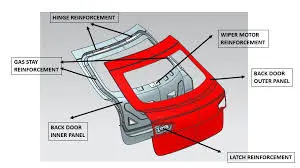
BackDoor Inner components Detailed View Samples:
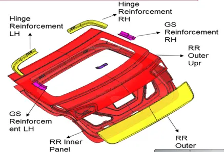
Desgning of Back Door:
- Back door consists of the following components
- Outer Panel Upper surface
- Outer Panel Lower surface
- Inner Panel surface
- Hinge Reinforcement
- Gas Stay Reinforcement
- Wiper Motor Mounting Reinforcement
- Latch and Stricker Reinforcement
Thickness Information:
- Thickness of outer and inner panel is 0.75mm
- Reinforcements is 1.5 mm
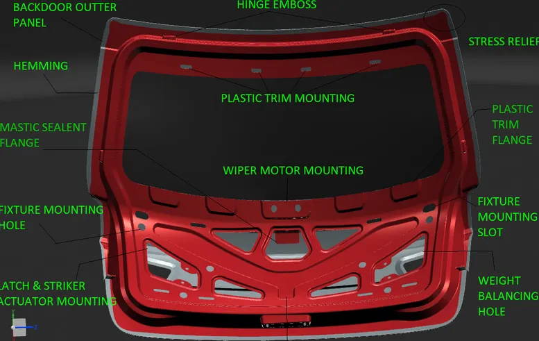
Sample Detailed view of BackDoor Components:
Outer Panel Upper Surface:
Outer panel class A surface will be provided and we will be checking for the surface continuity and repair the surface.
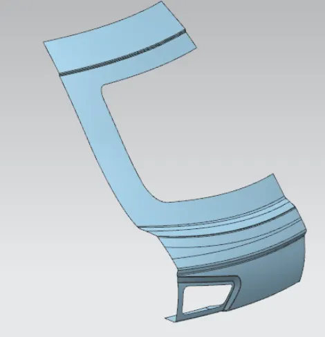
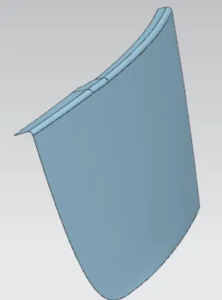
From the Class A surface will create the outer panel with the considerations for hemming process to join the inner and outer panel.
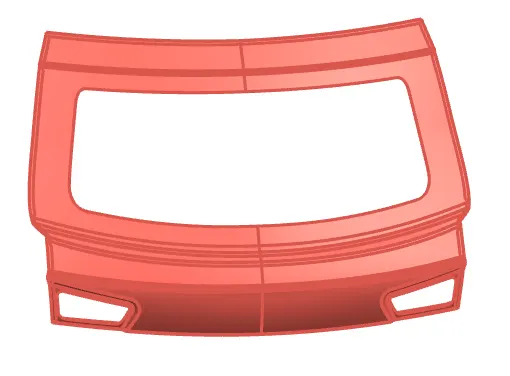
Image : Outer side of Upper Styling Surface
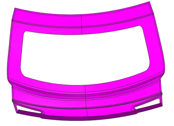
Image :Inner side of Upper Styling Surface
Outer Panel Lower Surface
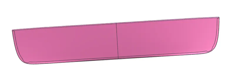
Image :Inner side of Lower Styling Surface
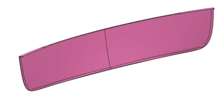
Image :Inner side of Lower Styling Surface
Inner Panel Surface:
- Backdoor will be rested on the rubber sealent portion attached to the car rear body to prevent the water entering inside the car inner compartments and also provide resistant to vibration.
- From the outer panel will offset the surface and create the sealing flange with minimum of 25mm and develop the connecting surface and also create the tooling direction from surfaces.
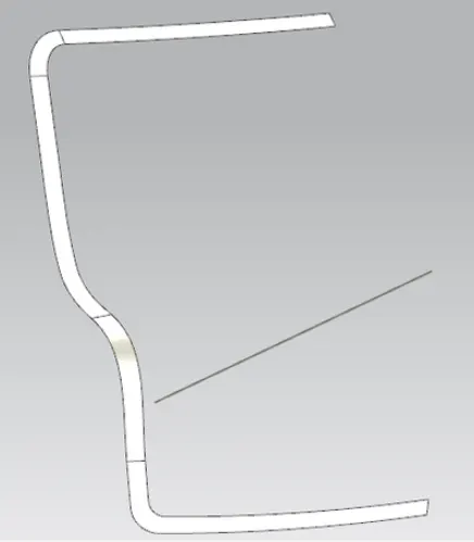
Image : Sealing Flange with Connecting Flanges
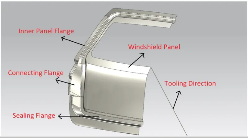
Sample Image : Sealing Flange with Connecting Flanges without cuts out and Support surfaces
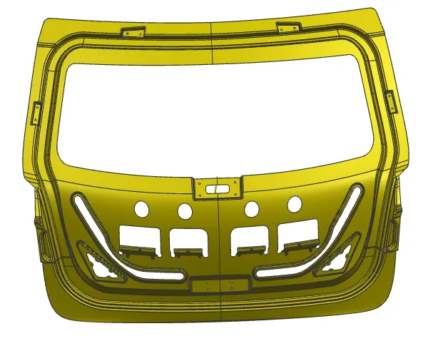
Image :outer side of Inner Panel
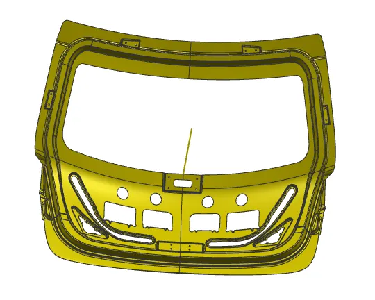
Image :Inner side of Inner Panel
- Inner panel is created and provide the cutouts to reduce weight and emposs to increase the stiffness of the sheet and also develop the reinforcement regions for the Hinge, Gas Stay, Wiper motor mounting and Latch.
- Emposs will be created like y shaped to dessipate the forces to outerside of the panel rather than inner side.
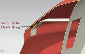
- Entended flanges with the distance of 5mm to provide the support structure and helps to mount mastic between the inner and outer panel.
Mastic Region:
Reinforceement:
The purpose of reinforcement is to provide attidional strength in that particular region of the components. These can be verified by performing the FEA analysis to determine the strength and deformation at that particular region based on the results we can provide the optimum reinforcement for particular regions.
Hinge Reinforcement:
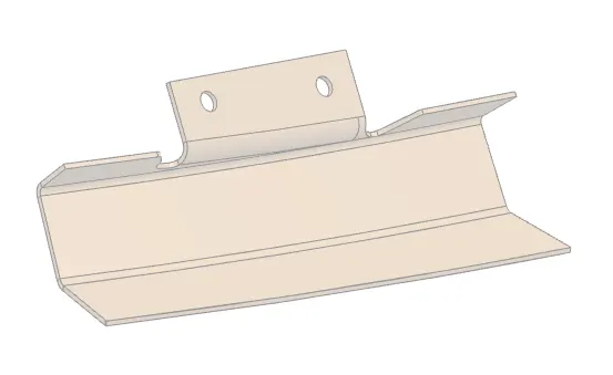
Image : Hinge Reinforcement Component
From the inner panel surface develop the reinforcements for hinge surface with required support and check with the analysis software to conform the required strength is acheived.
Gas Stay Reinforcement:
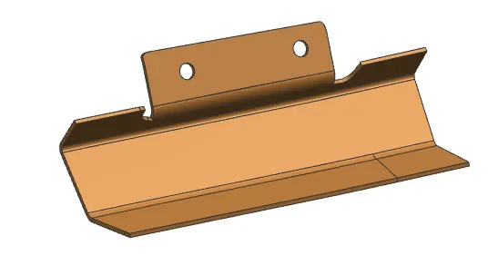
Image : Gas Stay Reinforcement Component
From the inner panel surface develop the reinforcements for Gas Stay attachment with required support and check with the analysis software to conform the required strength is acheived.
Wiper Motor Reinforcement:
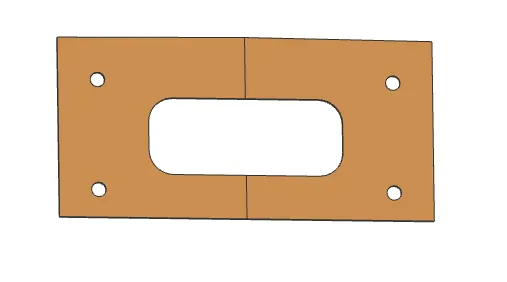
Image : Wiper Motor Reinforcement Component
From the inner panel surface develop the reinforcements for Wiper motor attachment with required support and check with the analysis software to conform the required strength is acheived.
Latch and Striker Reinforcement:
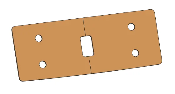
Image : Latch and Striker Reinforcement Component
Latch and striker wil be developed based on the design considerations.
Reinforcements:
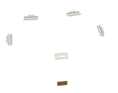
Image : Final Reinforcements Detailed overall Position view
Inner Panel with Reinforcements:
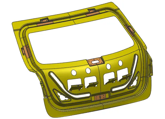
Image : Reinforcements Detailed view with inner Panel
Inner panel is fixed and reinforcements are attached to their respective position.
Assembly:
Thus the components are made individually and now it will wbe assembled together in assembly line. Outer panel lower and upper are spot welded together and fixed next inner panel with reinforcement are made with spot welding, both the inner panel and outer panel will be attached with the hemming process.
Latch and Striker Tragectory with Hinge Axis:
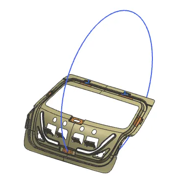
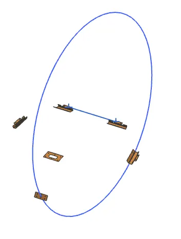
Image : Latch and Striker Tragectory with Hinge Axis
For positioning the Latch and striker with hinge axis, we need to create a line related to the hinge axis from that midpoint, draw a circle to striker axis and create a tangent line and make constrains so that it follow the tragetory .
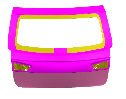
Image : Assembly of Back Door
Corner Reliefs:
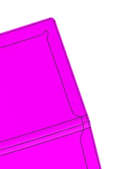
Image : Corner and Side reliefs
Reliefs and provide at the corner and sides to reduce the stress concentration in the particular region and avoid cracks at corners or other defects during deep drawing process.
Hemming:
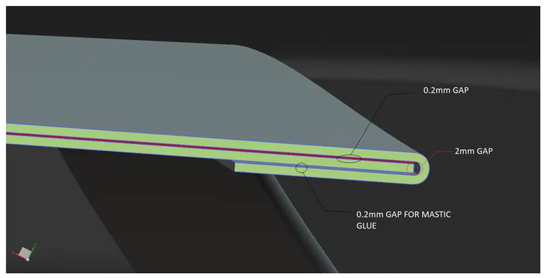
Sample Image : Hemming process with Dimensional parameters
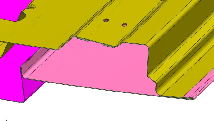
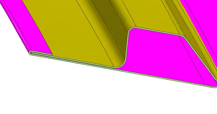
Sample Image :Cross Sectional view for Hemming between top and bottom panel
Hemming process is used to join the outer and inner panel with the dimensional requirement as mentioned in the images. Hemming process will be taking place in step by step process to bend the sheet, pre hemming , hemming and post hemming checks.
Draft Analysis:
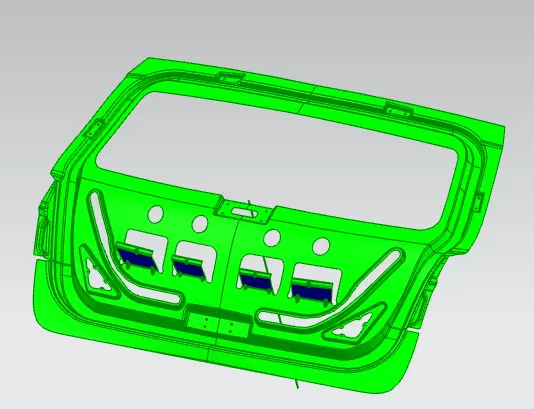
Draft analysis is carried out to ensure the part manufacturing considerations based on the tooling direction. consider draft angle of 7 degree and the part got satisying the requirement only in mastic support region can be made seperately with cutting off and bending tool or with lancing.