Design of backdoor
Introduction to Back Door Design
According to the given input IGS 3d data, the complete back door design should be executed with respect to the manufacturing feasibilty (Sheet metal), austhetic, open and close position of the back door (Trejactory)while accesing.
1. Fixing the Input data
As the given inpit 3d data has not properly attached with the adjecent surfaces and tangent as well. It was fixed
by removing the particular surface and has been created a brand new sheet. some surfaces had 3 edges so it cannot be obtained a proper tangent surface, that was also fixed by creating a brand new surafce by using THrough curve mesh command.
The below first image shows the surface does not have the edge and in the other image it has an edge in other end.
In the below image the removed faces are not properly attached with the adjecent faces so the sew operation cannot be obtained. So the proper surface needs to be created with 4 edges.
All the faces are united by a sew command after fixing the upper and lower panel of the back door input 3d data
The upper panel of the back door has been extracted to create as a single part and it has named back_door_upper_panel and saved.
Lower panel of the back door was also created such a way and it has named Back_door_lower_panel.
Offset the highlighted potion, extracted the offset body and made a face blend. Now it is named "connectig flange" in a group feature.
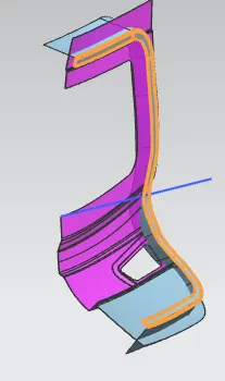
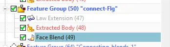
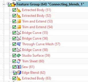
Now a conecting blends feature group has been created to attain the proper inner ribs of the back door door. In which in order to attain all the blends between the flnages can be made and its ribs were extracted twice to its availabilty in trim and extend features.
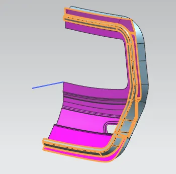
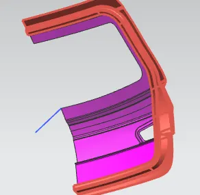
Then the outer panel surfaces were extracted, extended, law extended surfaces and trimmed in order to acheive the mastic in the lower panel and it is named "Door_LWR_Mastic" feature group.
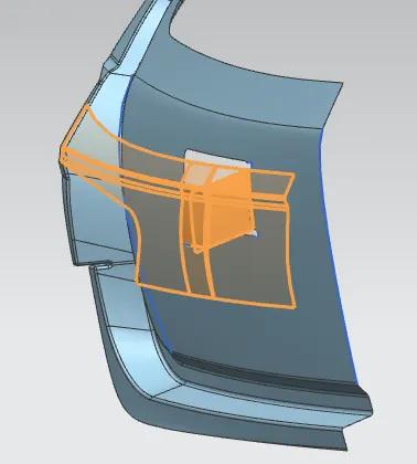
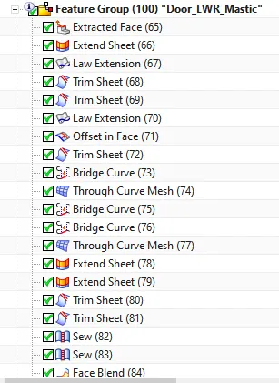
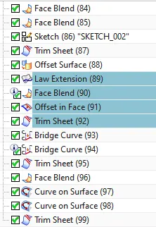
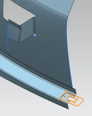
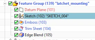
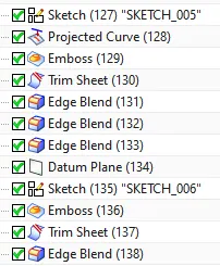
Latchet mounting were built on the lower panel where the door`s locking systems to be located in the bottom sideof the lower panel. A relevent sketch, emboss, trim sheet and edge blend features supports to acheive the latchet base.
Here in the image Hinge moutings were constructed in order to mount the hinge panel and strenghten the lower panel. Offet the lower panel surfce in a required portions and the following features have been used.
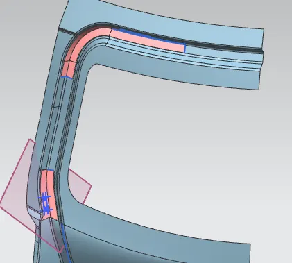
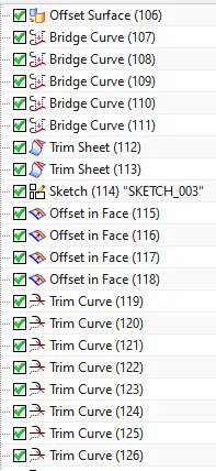
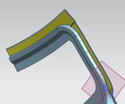
The below images show how the outer panel`s hemming was done. There any ways to achieve the hemming part but I have approached by offset the surface upto 8 mm from the outer panel.
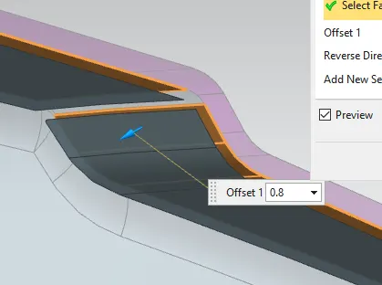
The hemming length was limiited 5mm by offset curve from the edges of the offset surfaces as shown in the image below.
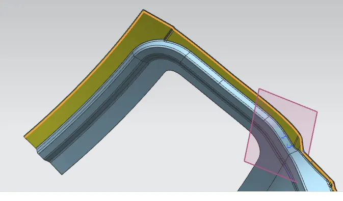
The hemming was aceived as shown in the below image by making
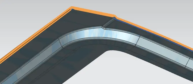
There are many cross-section curves were built between the outer panel and the offset suface throught the panles where the hemming process should be done.
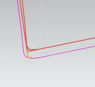
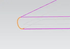 images shows the cross-section curves
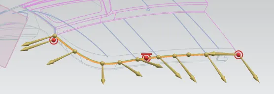
The above image shows how the hemming was done in the lower outer panel by through curve mesh feature.
Finally all hemming surface and the lower and upper outer panels were sewed to make a single sheet. as shown in the below highlighted images.
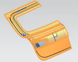
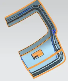
Eventually all the upper, lower outer and inner panels has been applied thickess 0.75 mm accroding to the sheet metal standards being followed to the car door panels.
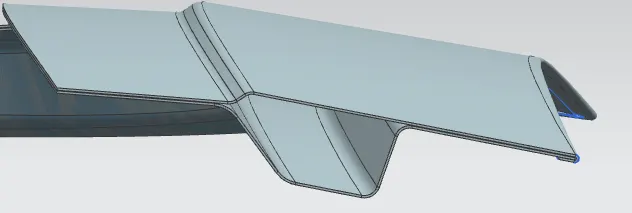
In the below images confirms the thicken sufaces are mirrored in order get the complete back door panels. To acheive the complete profile of the panel mirror feature has been used. And for the final touch all the respective mirror bodies were united.
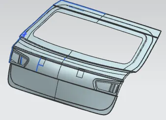
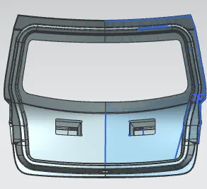
And those featured are grouped into "mirror_gemotry" .
Important Note - As my 3d data is more than 20 MB, I am unable to submit my challenge in the below browser, inspite I am sharing you my output data in google drive. Find the link below. if you find any difficulty to download from the link please let me know.
https://drive.google.com/drive/my-drive