Design of backdoor
1.1 Aim:
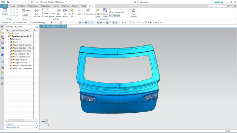
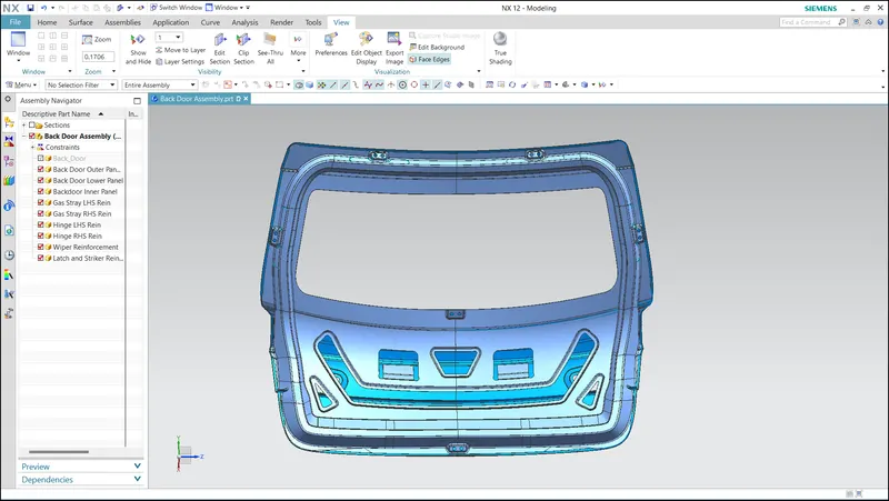
The backdoor design was developed using a top-down assembly approach in NX CAD, ensuring the incorporation of all necessary mountings and reinforcements. The design included precise placements and integration of mountings for hinges, gas stays, wiper motor mountings, and latch strikers. The top-down assembly methodology allowed for efficient collaboration between components, ensuring proper fitment and functionality of the backdoor assembly. The resulting design achieved the desired structural integrity and functionality while accommodating the required mountings and reinforcements.
2.1 Backdoor:
The backdoor, also known as the hatch, tailgate, trunk-lid, or boot-door, is a vital component of a vehicle mounted on the rear side. Its primary function is to cover the luggage area, creating an airtight seal to prevent water from entering the car. The backdoor is typically located behind the last passenger seats and features various essential elements such as striker mounting, wiper motor mounts, tail lamps, hinges for support, gas stays for smooth opening and closing, as well as radars, cameras, and other features.
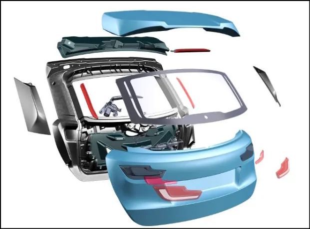
In the context of vehicle doors, the backdoor serves as an entry and exit point for accessing the luggage compartment. Gas stays are commonly used to assist in lifting the backdoor, reducing the effort required. Some luxury vehicles are equipped with powered backdoors driven by electric motors, offering enhanced convenience. In Europe, hatchback or station wagon models are often classified as 3-door or 5-door, with the rear hatch considered as a door because it provides access to the passenger compartment.
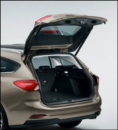
Safety is a critical consideration in backdoor design, with specific requirements to meet rear collision safety standards. Ensuring compliance with these safety regulations is essential to ensure the protection of occupants and mitigate potential risks.
2.2 Types Of Backoor:
Types of backdoors based on the position of the hinge axis include,
- Top-mounted
- Side-mounted
- Bottom-mounted
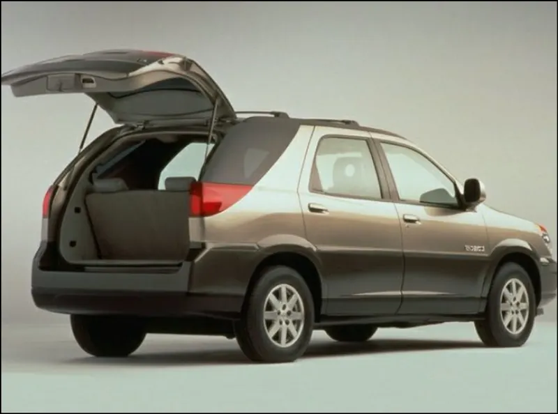
1. Top mounted: In this configuration, the hinge is mounted on the upper side of the car, allowing the backdoor to open in an upward direction. Examples of vehicles with top-mounted backdoors are hatchbacks and sport utility vehicles (SUVs). Hatchbacks typically have a 2-box design with a separate passenger compartment and boot space, and the rear seat can be folded to increase the storage capacity.
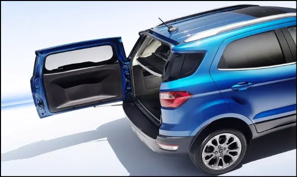
2. Side mounted: With side-mounted backdoors, the hinges are positioned on the sideways of the rear side of the vehicle. This arrangement is commonly found in vans and ambulance vehicles. Side-mounted backdoors are suitable for medium to heavy-duty goods and carriage services, providing convenient access to the cargo area.
3. Bottom mounted: In the case of bottom-mounted backdoors, the hinges are mounted on the bottom of the rear side of the vehicle. This configuration is often seen in heavy-load capacity vehicles or those with a platform-type chassis, such as trucks. Bottom-mounted backdoors are designed to withstand the weight and demands of heavy-duty applications.
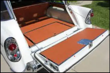
Each type of backdoor configuration offers distinct advantages based on the intended use and vehicle design. Whether it's the convenience of top-mounted hatchbacks, the accessibility of side-mounted doors for cargo handling, or the robustness of bottom-mounted doors for heavy-duty applications, the choice of hinge position plays a crucial role in determining the functionality and suitability of the backdoor.
2.3 Working Mechanisms in Backdoor:
Types of backdoors based on their working mechanisms include
- Gas Stay Type
- Powered Lift System
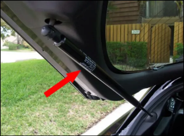
1. Gas Stay type: The gas stay type backdoor mechanism is widely used across various car segments, from lower-end cars to luxury vehicles. This mechanism consists of several components, including hinges, the door itself, gas stays, and rubber beadings for sealing the door. The gas stays provide support and assistance in opening and closing the backdoor, ensuring smooth operation. This type of mechanism offers convenience and ease of use for opening and closing the backdoor.
2. Powered Lift System: The powered lift system is a sophisticated mechanism used for automatically opening, closing, and releasing the latch of the trunk or liftgate. This system is activated by a touch button or switch, enabling convenient operation. Components of the powered lift system include a power latch, anti-pinch switch, PTG assembly, and PTG main switch. When the switch is pressed, the power latch releases the latch, allowing the entire backdoor to open automatically. The anti-pinch switch is strategically positioned to prevent accidental hand insertion during the operation of the door, enhancing safety.
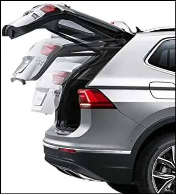
These different working mechanisms offer varying levels of convenience and automation in operating backdoors. The gas stay type provides support and controlled movement, while the powered lift system adds automation and ease of operation, particularly in luxury vehicles. The choice of working mechanism depends on the desired functionality, user experience, and vehicle specifications.
2.4 Manufacturing Process:
The manufacturing process, stamping and deep drawing, play a crucial role in shaping sheet metal into the desired forms for backdoors and other automotive components. They enable the production of lightweight and structurally sound parts, contributing to the overall quality and performance of vehicles. Additionally, these methods offer efficiency in large-scale production, ensuring cost-effectiveness for the automotive industry.
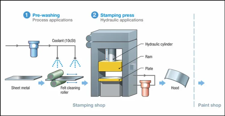
1. Stamping Process: The stamping process, also known as pressing, involves taking flat sheet metal, either in coil or blank form, and feeding it into a stamping press. Inside the press, a tool and die surface shape the metal into the desired form. Various techniques such as punching, blanking, bending, coining, embossing, and flanging are utilized to shape the metal. Stamping allows for high precision and mass production of automotive components, including backdoors. It is a cost-effective method for creating complex shapes and achieving consistency in manufacturing.
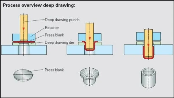
2. Deep Drawing: Deep drawing is a process used to manufacture automotive components with a solid and durable wall surrounding the full diameter of the part. This technique creates a seamless structure that is resistant to leaks, water penetration, and air infiltration, making the components more reliable in demanding operational and environmental conditions. Deep-drawn parts, including backdoors, can be produced with a high level of accuracy and dimensional stability, ensuring a precise fit and function.
2.4.1 Tailor Welded Blank Method:
Tailor Welded Blank (TWB) is a manufacturing method where two separate pieces of sheet metal are welded together before the stamping process. This technique allows for the welding of different grades, thicknesses, or corrosion coatings of sheet metal, providing the required properties in different areas of the vehicle without increasing the number of tools required for part formation. TWBs offer a high degree of design flexibility, allowing for the creation of large blanks from smaller sheets. By selectively placing different thicknesses of material, weight reductions can be achieved. For example, the production of the door inner panel can utilize TWBs, as the only strength requirement is in the region where the hinges attach to the panel.
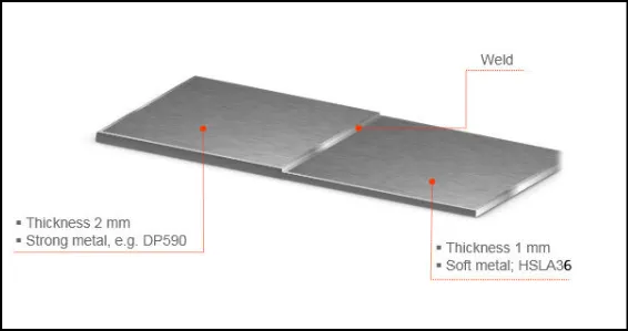
Implementing Tailor Welded Blanks in manufacturing processes contributes to weight reduction in vehicles. It offers design versatility, cost efficiency, and improved material utilization, ultimately leading to lighter and more efficient automobiles.
2.5 Design considerations for backdoor:
-
Rear Visibility Criteria: Ensuring adequate visibility for the driver from the rear seat is essential for safety. The design should optimize the rear window size and positioning to provide clear visibility.
-
Crash Requirements: The backdoor design must meet crash regulations and requirements to ensure occupant safety in the event of a collision. It should incorporate appropriate reinforcement structures and energy absorption mechanisms.
-
Space Requirements: The backdoor design should consider the amount of space needed for luggage or cargo storage. It should provide sufficient volume while maintaining structural integrity.
-
Accessibility: The design should facilitate easy access to the luggage compartment. Considerations include the size and shape of the opening, handle placement, and ergonomic considerations for opening and closing the door.
-
Backdoor Opening Style: Different opening styles such as liftgate, swing-out, or sliding mechanisms have different implications for design and functionality. The choice of opening style should align with the vehicle's overall design and user requirements.
-
Mountings: Proper mountings for components such as hinges, gas stays, latch, wiper motor, and striker should be integrated into the backdoor design. These mountings should provide stability, durability, and ease of operation.
-
Sealing Criteria: To ensure an airtight and watertight seal, the backdoor design should incorporate sealing flanges and appropriate sealing materials. The design should prevent air and water infiltration into the vehicle's interior.
-
Clearances and Reliefs: Clearances and reliefs should be designed to prevent interference between moving components, such as the backdoor and adjacent body panels or trim pieces. These considerations ensure smooth operation and avoid potential damage.
-
Gap and Flushness Requirements: The design should meet specific tolerances for panel gaps and flushness to maintain a visually pleasing appearance and provide a seamless integration with the rest of the vehicle body.
-
Joining Techniques: The backdoor design may involve various joining techniques, such as hemming and spot welding, to assemble different panels. The selection of appropriate joining methods should ensure structural integrity and durability.
-
Thickness of Panels: The design should specify the appropriate thickness for different panels, including the outer panel, inner panel, and reinforcements, to meet strength and stiffness requirements.
3.1 Backdoor Design and Assembly:
The design and assembly of a backdoor involves the integration of various components and reinforcements to create a structurally sound and functional unit. The assembly process can be divided into multiple steps to ensure seamless integration of different parts. Here is a breakdown of the main components and their assembly:
-
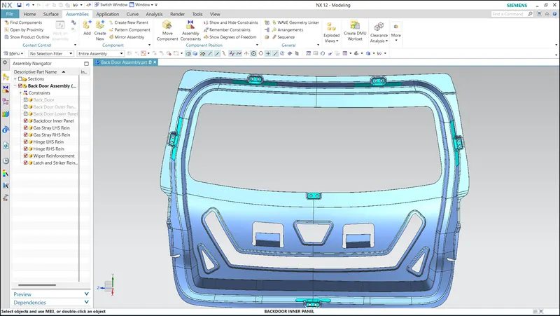
Inner Panel: The inner panel serves as the backbone of the backdoor assembly. It provides strength and stability to the door and serves as a mounting point for various accessories such as hinges, glass guide channels, trim, latch, etc. The inner panel is typically manufactured through a deep drawing process, where a blank is inserted into a mold and formed with the necessary embosses and mounting features.
-
Outer Panel: The outer panel is the visible and aesthetic part of the backdoor. It is responsible for providing an attractive finish and can include provisions for tail lamps, rear fog lamps, license plate mountings, and wiper motor assembly in hatchback cars. The outer panel is coated with multi-stage coatings to ensure scratch resistance, rust prevention, and an appealing appearance.
-
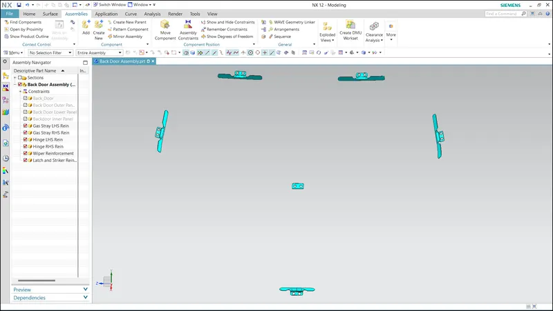
Hinge Reinforcement: Hinges support the weight of the backdoor, so hinge mount reinforcements are provided to strengthen the attachment points. The design of the hinge reinforcements ensures that the hinges operate freely, and holes are strategically placed for electrical wiring looms.
-
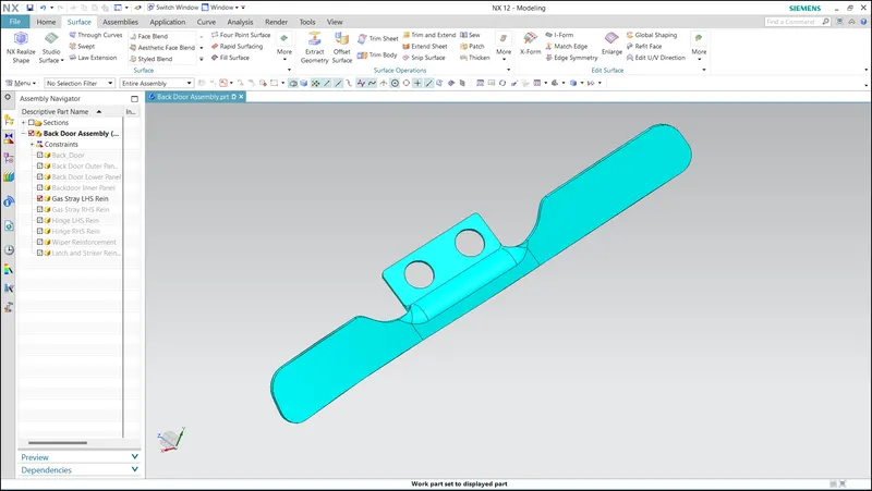
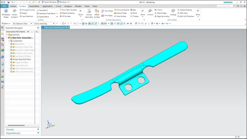
Gas Stay Reinforcement: Gas stays or power lifters are responsible for holding the backdoor in an open position. Reinforcements, such as angled or diabolic embosses, are provided for the gas stay mounts. The reinforcements are made with a thicker sheet to withstand the loads exerted by the gas stays.
-
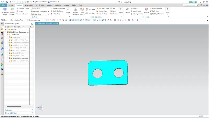
Wiper Motor Reinforcement: A dedicated space is reserved near the window for the wiper motor assembly. A cavity is created to accommodate all the necessary components of the wiper motor. This ensures proper functionality and integration of the wiper system with the backdoor.
-
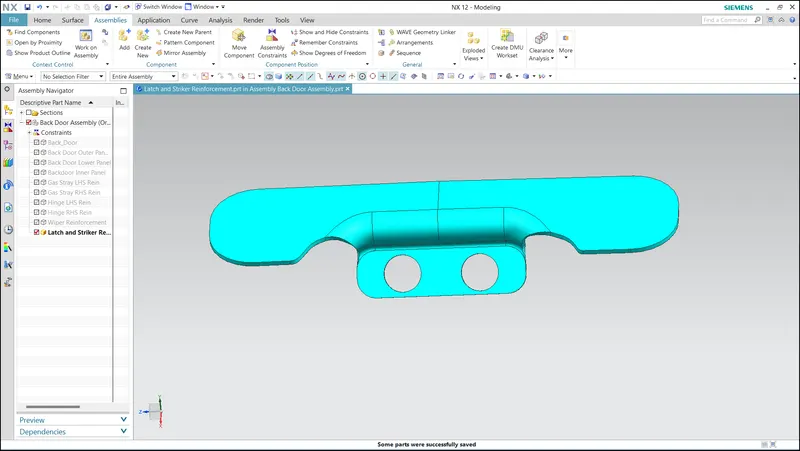
Latch and Striker Reinforcement: At the bottom of the backdoor, a latch and striker assembly is located to keep the door securely closed. Reinforcements are added to strengthen the attachment points of the latch and striker mechanism. This ensures the proper functioning of the locking mechanism and enhances overall security.
3.2 Design Constraints Followed:
- Thickness of Outer Panel = 0.75mm
- Thickness of Inner Panel = 0.75mm
- Thickness of Reinforcements = 1.5mm
3.2 Designed Components:
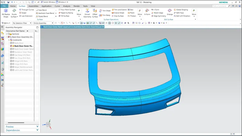
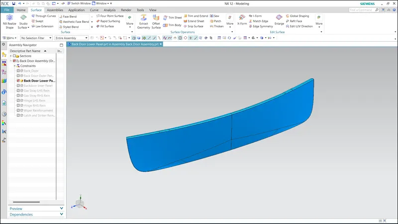
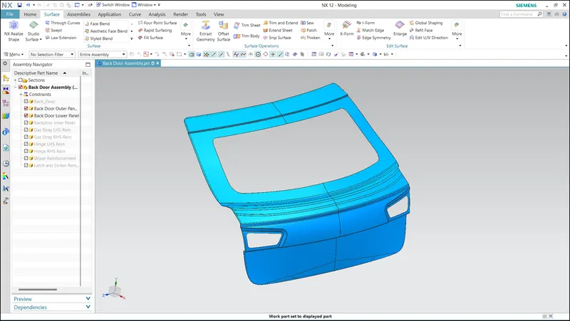
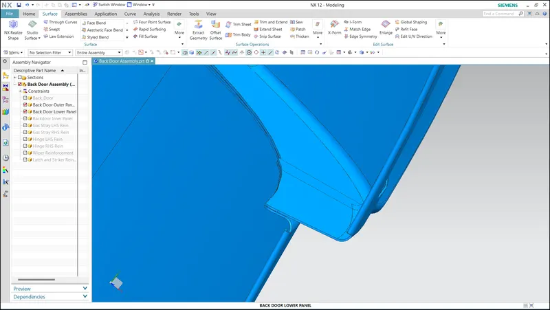
1. Outer Panel: The Outer Panel of this Backdoor consists of Upper and Lower panel where both of them thickened seperately and spot welded at the end of the manufacturing process.
- Outer Panel Upper
- Outer Panel Lower
- Outer Panel Upper and Lower
- Spot Welding Area
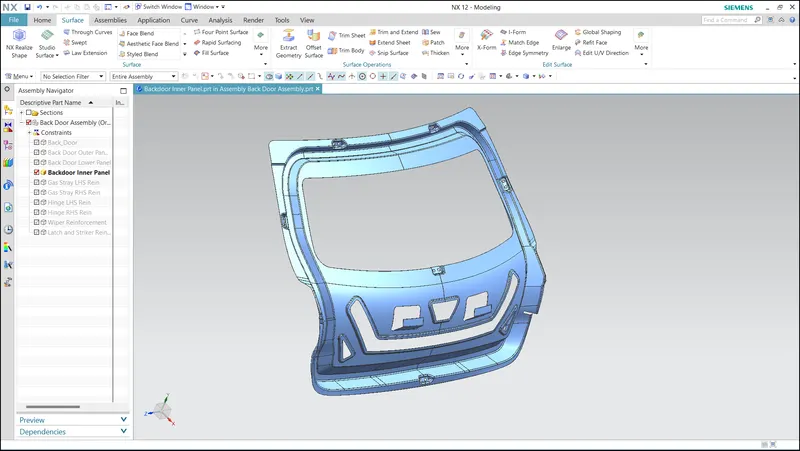
2. Inner Panel:
- Front View
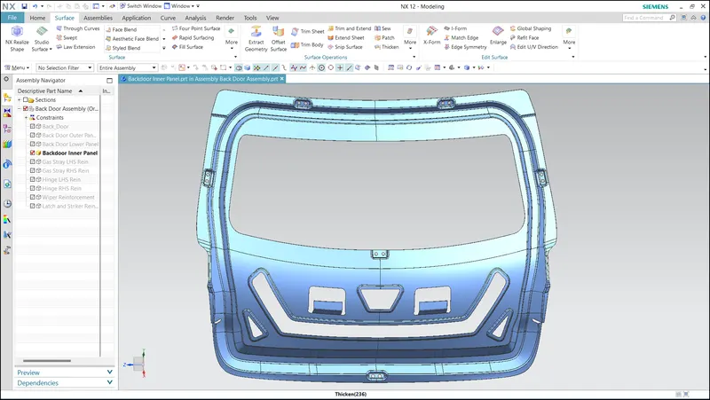
- Isometric View
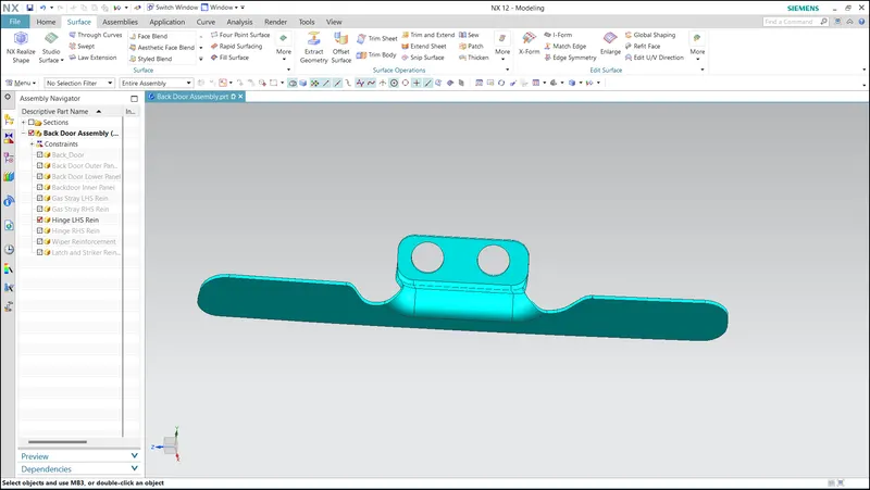
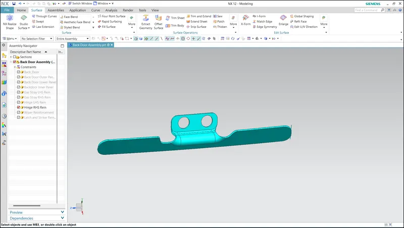
3. Hinge Reinforcement:
- LHS
- RHS
4. Gas Stay Reinforcement
- LHS
- RHS
5. Wiper Reinforcement
6. Latch and Striker Reinforcement:
7. Inner Panel With Reinforcement:
8. Reinforcements:
3.3 Tooling Direction:
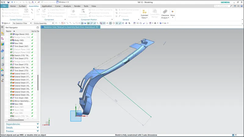
Tooling direction determines the axis along which molds open and close. This ensures easy ejection of components from molds and reduces tooling costs by using a single reference vector for creating surfaces, embosses, and draft angles. Aligning these elements with the tooling direction streamlines manufacturing and optimizes mold design for cost efficiency and high-quality backdoor production.
3.4 Draft Analysis:
The draft analysis tool is utilized by designers and mold tooling manufacturers to ensure the appropriate application of draft angles to the faces of plastic parts. This analysis helps verify draft angles, assess angle variations within a face, and identify parting lines, injection points, and ejection surfaces in the parts.
For both the inner and outer panels, draft analysis is conducted using the tooling direction as the reference vector. It is important to adhere to sheet metal design considerations, where a minimum draft angle of approximately 7 degrees is recommended to facilitate smooth ejection of the part.
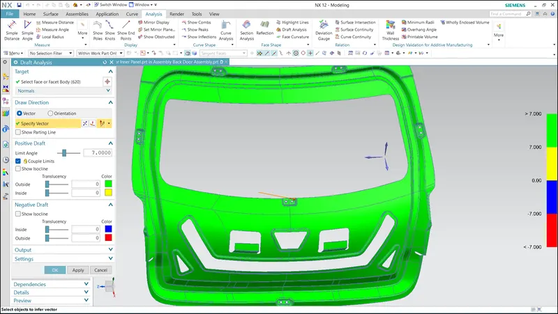
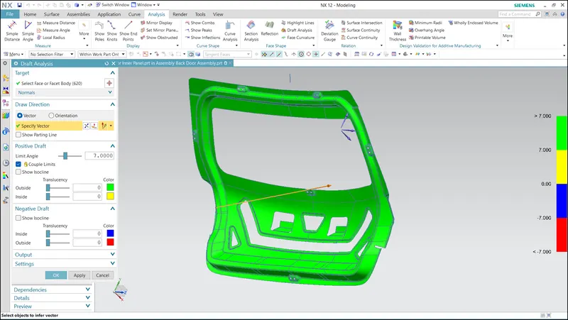
Upon conducting the draft analysis, it is evident that all the parts have successfully passed the required draft angle specifications.
3.5 Latch and Striker Trajectiory:
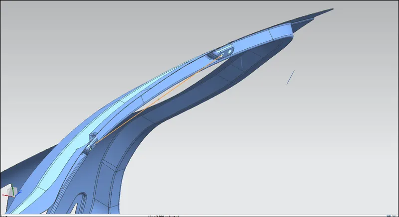
To determine where to position the slot on the latch and striker reinforcement mounting, we use a method that involves tracing the trajectory of a circle. To do this, we consider the distance between the hinge axis point and the center of the slot, which is called the radius. This radius acts as a guide or measurement that helps us accurately determine the location of the slot on the mounting. By following the trajectory of the circle, we can ensure that the slot is positioned correctly for proper functionality.
- Trajectory
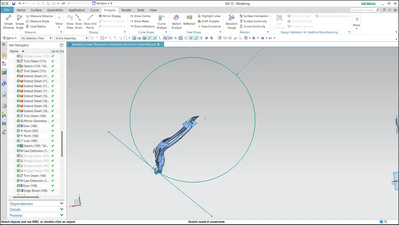
- Hinge Axis
3.6 Hemming:
Hemming is a sheet metal joining technique commonly used in manufacturing. There are two types of hems: closed hems and open hems. In closed hems, a sheet metal is bent over another part of the sheet metal, creating a secure and seamless connection without the need for additional welds or rivets. This type of hemming provides a smooth and clean surface finish. Open hems, on the other hand, involve bending the edge of a sheet metal outward, leaving a visible edge. Hemming is a versatile and efficient method for joining sheet metal parts, ensuring structural integrity and aesthetic appeal in various applications.
- Hemming
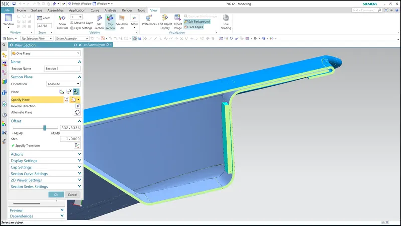
- Relief Upper Panel
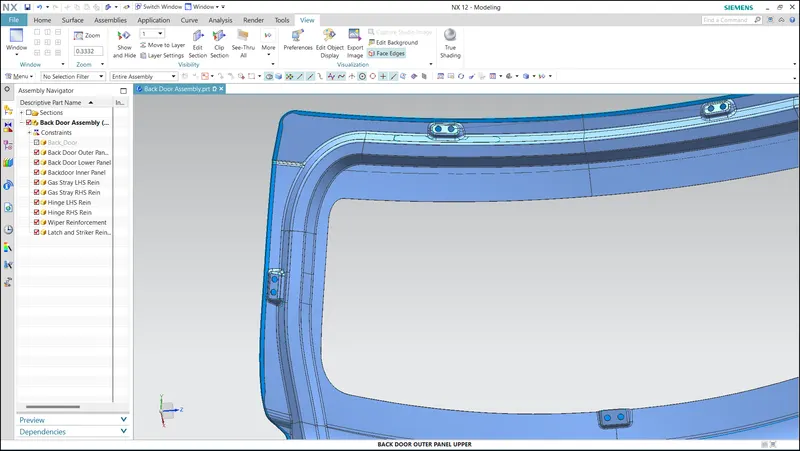
- Relief Lower Panel
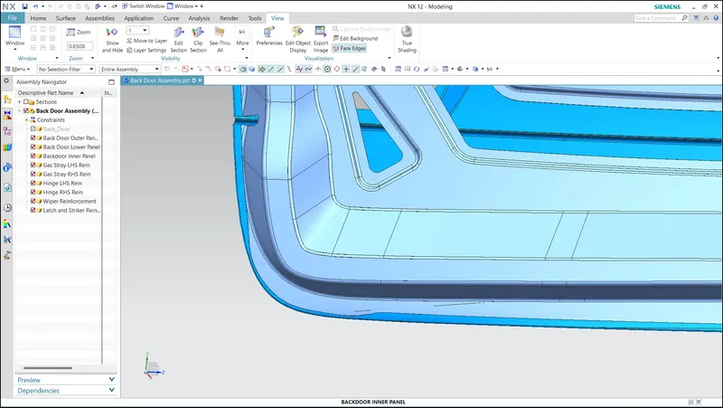
4.1 Conclusion:
The sheet metal design principles have been effectively applied in the design of the entire back door assembly using NX CAD. Various factors such as rear visibility criteria, crash requirements, space utilization, accessibility, and sealing considerations have been taken into account. Through careful analysis, drafting, and tooling direction determination, the back door assembly has been designed to meet both functional and aesthetic requirements. Overall, the application of sheet metal design principles has ensured the successful creation of a robust and well-designed back door assembly.
- Backdoor Asembly