Design of backdoor
AIM
- Detailed report for the back door design by explaining the design methodologies and about the components developed the design.
- Perform the draft analysis along the tooling direction and include the snapshot in the report.
BACKDOOR DESIGN
INTRODUCTION
A back door is a type of door opening, typically hinged on its front edge, but sometimes attached by other mechanisms such as tracks. It is provided at the end of the vehicle opposite to which the engine is located. It is generally available in all automotive car. Doors most often integrate side windows for visibility from inside the car and can be locked to secure the vehicle. Back door constituted by a main body which includes an outer panel and an inner panel combined together. The material of back door is aluminium and steel. In order to give strength, it is provided with reinforcement on the inner panel. Opening and closing usually this process will be done manually. One has to get down the car to open and close the tail-gate with the car key. In advanced cars, the driver can press the button in his cabin to open and close the tailgate while sitting in his seat.
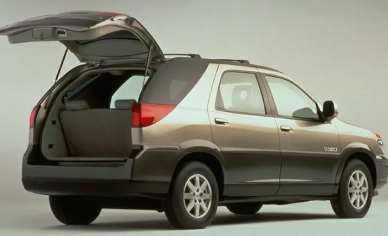
- Backdoor is the hinged door at the rear part of a vehicle and can be moved up or down.
- Backdoor are one of the type of door of the vehicle which are located next to the passenger seat.
- It is placed in such a way that it can open upwards, downwards or from the side.
- Back door can be operated manually or by the power lifter.
- Back door is also known as tail gate or rear gate.
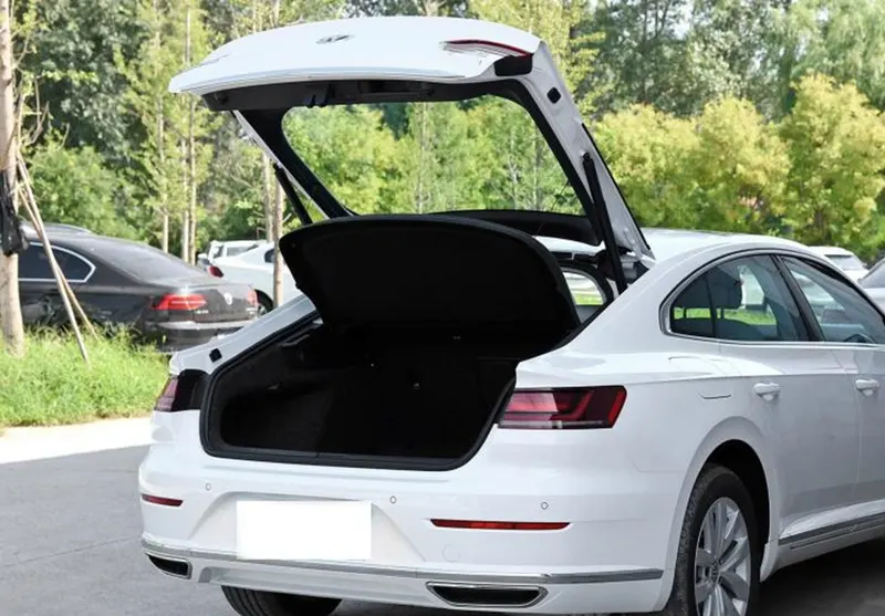
FUNCTION OF BACK DOOR
- It lets us access the boot space or trunk.
- Some of the vehicle also have back door for passenger in and out, where seat is available for the passenger.
- It can be locked to secure the vehicle.
- The backdoors are also designed in such a way that, in the case of a rear end collision, the backdoor plays a role in diverting the impact energy away from the passenger cabin by providing various load paths to the rear pillars and other components in the vehicle structure.
- Back door is made aerodynamic in shape to reduce air effect.
- It is designed in such a way that it can reduce the NVH level.
- Parking sensor and rear view camera can also mounted on it in some of car.
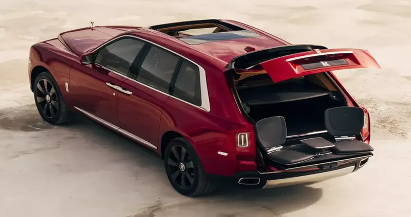
DIFFERENT TYPES OF BACK DOOR
There are many variation of designed on the automobile back door is available.
- Top mounted back door
- Bottom mounted back door
- One side mounted back door
- Top and bottom mounted back door
- Both side mounted back door
1. TOP MOUNTED BACK DOOR
In this type, back door is mounted in top of the car. The opening and closing direction is upward and downward in top mounted back door. Top mounted back door or tail gates provide greater rear visibility compared to side mounted and bottom mounted. Opening and closing can be done by manually or by the power lifter. Gas stay is also used for supporting in this type of back door. Mostly top mounted back door car is used in modern cars, station wagon, pickup truck etc.
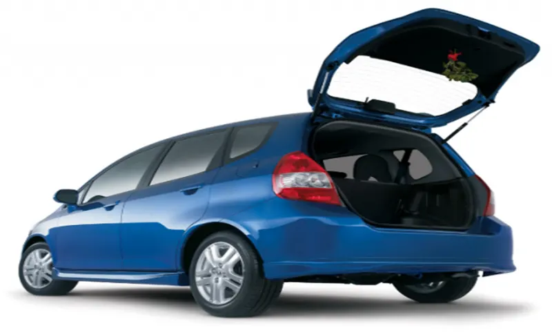
2. BOTTOM MOUNTED BACK DOOR
In this type, back door is mounted in bottom of the car. The opening and closing direction is upward and downward in bottom mounted back door. This type backdoor system is used in the car type such as estate type car, pickup trucks and some luxury SUVs. The bottom split is used as a support or even as a table for the tour going people. Opening and closing can be done by manually or by the power lifter.
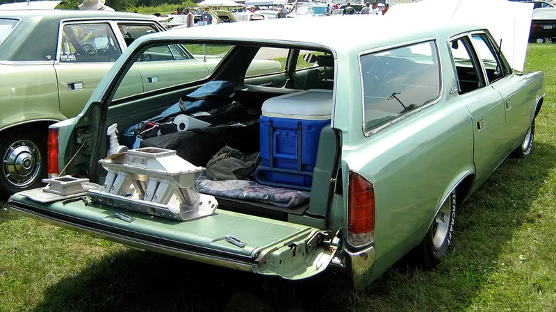
3. ONE SIDE MOUNTED BACK DOOR
In this type, back door is mounted in side of the car. The opening and closing direction is left to right or right to left from the side. Opening and closing in this type of back door is operated manually. This type of door can be easily accessed than top and bottom mounted back door. These door also save accidental head impacts. It is a lot easier to load and unload items in the side mounted doors. These doors are more convenient for the goods handlers for long pipe and lengthy components where one door is kept open.
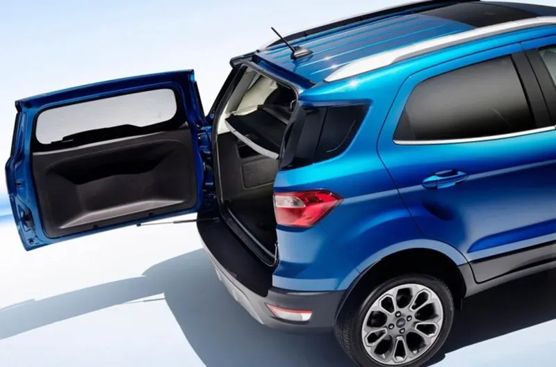
4. TOP AND BOTTOM MOUNTED BACK DOOR
In this type, back door is mounted in both top and bottom of the car. The opening and closing direction is upward and downward. Opening and closing can be done by manually or by the power lifter. Most of these type of back door is operated by power lifter.
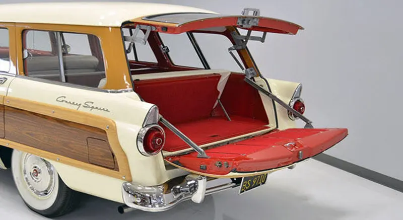
5. BOTH SIDE MOUNTED BACK DOOR
In this type, back door is mounted in both side of the car. The opening and closing direction is left to right or right to left from the sides. Opening and closing in this type of back door is operated manually. This type of door can be easily accessed than top and bottom mounted back door. These door also save accidental head impacts. It is a lot easier to load and unload items in the side mounted doors. Generally this type of door is used, where the storing area is required more. This type of back door is used in heavier vehicle (like truck), van etc.
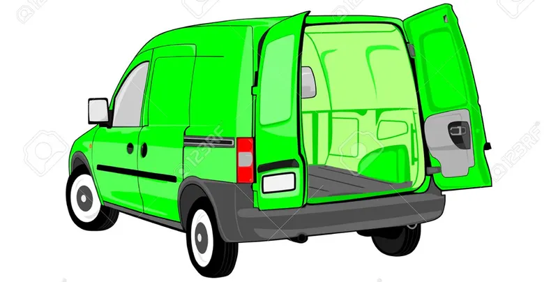
BACK DOOR MATERIAL SELECTION
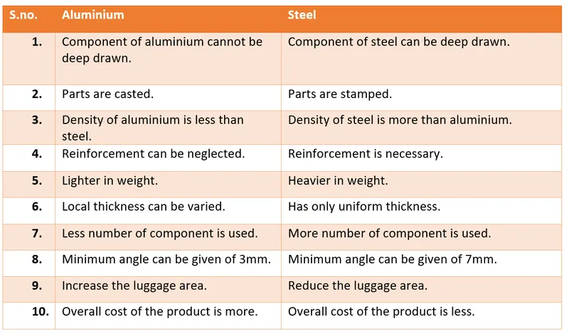
The backdoor material depending on how expensive the vehicle and the budget for its development. Selection of material for back door is
DESIGNING PROCESS OR DESIGNING METHODOLOGIES
1. COLLECT INFORMATION
- Collecting all the information for design of back door.
- Collect all the basic information about assembly of back door.
- Collect the dimension of roof as well as fender, because the back door is attached with both section.
2. MASTIC SEALANT
- Mastic sealant is used to join the inner and outer panel.
- Provided a gap of 5mm for the mastic sealant.
- Mastic sealant provides strength at around 80 mm so we need to put these mastic points in such a way that it covers the most of the back door except reinforcement area.
- It is placed between the outer and inner panels. Initially is it in paste form, but after the hot furnace bath, it gets hardened thus joining the outer and inner panel.
3. THICKNESS OF BACK DOOR
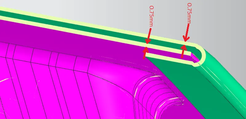
- After all consideration, thickness of the outer panel and inner panel is taken as 0.75mm.
- Thickness of all reinforcement is taken as 1.5mm.
- Provide the thickness by maintaining the gap for all other process.
4. EMBOSS
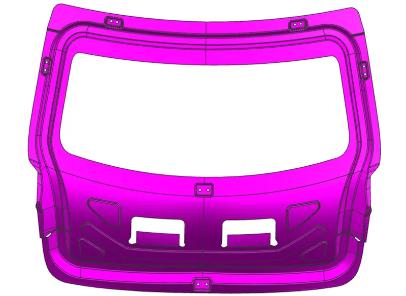
- Embosses has been given to create extra strength in inner panel and embosses design needs to be inspired by force dissipation phenomena.
- This also help in weight reduction of inner panel.
- Emboss are designed in such a way that it divert the forces towards the hinge assembly. So that the force do not act on the passenger inside the car.
- Emboss is given so that during the crash the energy is dissipated outside / away from the vehicle occupants and along with the other cut outs to reduce the weight.
- Embosses are given to make the inner panel stiffer and good endurance while crash. It is created in ‘Y’ shape to allow the force to flow and get dissipated outside and hence to protect the vehicle occupants.
- The inner panel surface is not a flat one. It is a curvy surface. Hinges will not fit properly on a curvy surface. So, the flat surface is created at some distance from the inner panel, and using law Extension, emboss is created onto.
- Emboss is created in all area like for hinge reinforcement, latch and striker reinforcement, gas stay reinforcement, wiper motor reinforcement etc.
PROCESS OF EMBOSSING
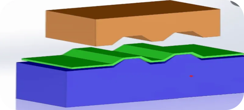
- This process is done by matched male and female roller. This process is also done by passing sheet or a strip of metal between rolls of the desired pattern.
- An Embossing is created by pressing a female Die into a male Counterforce with the substrate to be embossed between the two.
- The metal sheet is drawn through the male and female roller dies, producing a pattern or design on the metal sheet. Depending on the roller dies used, different patterns can be produced on the metal sheet. The pressure and a combination of heat actually "irons" while raising the level of the image higher than the substrate to make it smooth.
- In most pressure embossing operation machines, the upper roll blocks are stationary, while the bottom roll blocks are movable. The pressure with which the bottom roll is raised is referred to as the tonnage capacity.
5. REAR VISIBILITY CRITERIA
- Rear visibility criteria allow the visibility of the things.
- The driver should be able to see from his seat to the rear side of the car by mirror attached to the front windshield.
- To drive the car in proper way and with safety, rear visibility criteria is most important.
6. BOOT SPACE
- Boot space is also consider for the designing of back door.
- The gap between inner panel and outer panel is provided in such a way that strength, stiffness and section modulus is maintained while giving enough boot space.
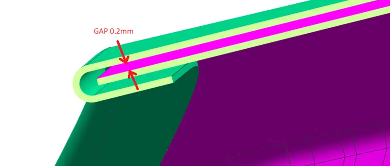
7. HEMMING
- Hemming is the process of joining of two surfaces using set of rollers and to bend the parent part over the sub part.
- Hemming is a forming operation in which the edges of the sheet are folded or folded over another part in order to achieve a tight fit.
- The accuracy of the hemming operation is very important since it affects the appearance of the surface and surface quality.
- They hide defects such as rough edges and burrs
- They make the edges safer to handle.
- Hemming should be done by providing gap of 0.2mm between inner panel and outer panel.
HEM TYPES
The different sheet metal hems based on the hem shape are as follows:
- Flat or closed hem
- Open hem
- Teardrop hem
- Rope hem
- Rolled hem
A. FLAT OR CLOSED HEM-: In a flat or closed hem, the part of the edge that bends sits completely flush over the rest of the metal sheet. The angle between the returning flange and the sheet metal is 180 degrees. The inside radius is zero and thus, there is no gap between the returning flange and the metal sheet.
Closed hems require a lot more power and tonnage from the presses than open or teardrop hems and it is also not advised for metal sheets that are over 2-3mm in thickness since the sheets are likely to fracture.
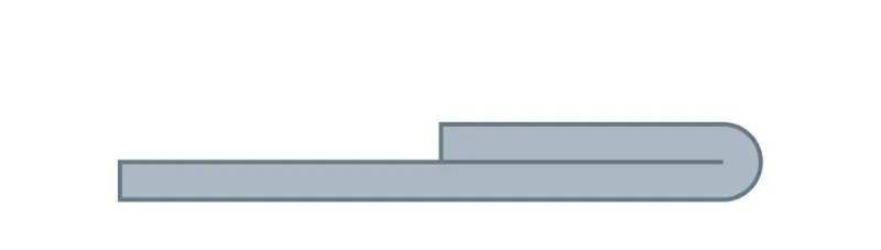
B. OPEN HEM-: In an open hem, the returning flange is folded over the sheet metal but there remains an air pocket between the two. The bend angle in this hem type is also 180 degrees.
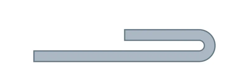
C. TEARDROP HEM-: In a teardrop hem, the returning flange is bent beyond 180 degrees. The resulting shape resembles a teardrop.
It is perfect for materials that do not have the required ductility to provide closed hems. Teardrop hems are used for fragile materials such as aluminium.
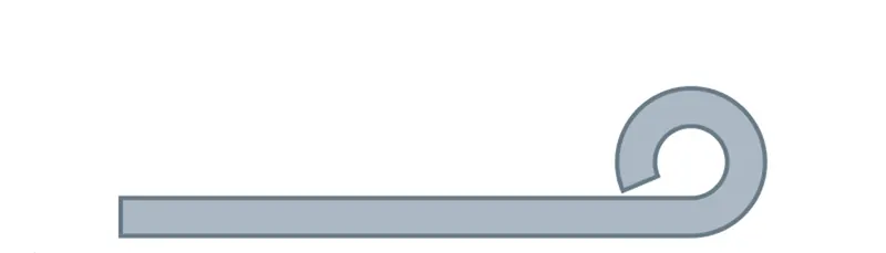
D. ROPE HEM-: A rope hem has a returning flange at a bent of more than 180 degrees. Once the hem achieves the shape of an open hem, the returning flange is pressed onto the part surface through a flattening die.
The edge is bent in shape similar to an open hem and then the second piece to be connected is inserted into the gap between the metal sheet and the returning flange. Further pressing takes place making the second parts sit flush between the metal sheet and the returning flange and create a joint.
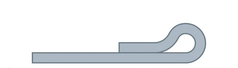
E. ROLLED HEM-: In a rolled hem, the bent portion of the sheet metal is tucked back into itself. This creates smooth round edges all around for holding the part from the hemmed edges. This process is also commonly referred to as curling.
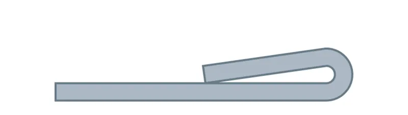
The hemming process can be carried out in one of the following two ways:
- Die hemming process
- Roller hemming process
8. RELEIF
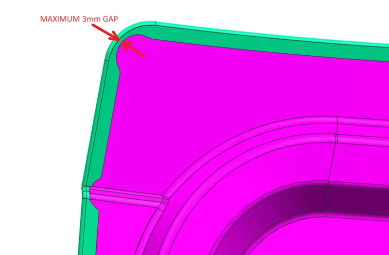
- After the hemming process is done, now we need to provide corner relief on the corners and wherever it required.
- The relief section is given maximum of 3mm.
- When each roller is crossing over the edges, the roller cannot go through all the region. And when similar roller passed over the sheet, there are some tendency when the sheet metal vibrate during the motion. If the forces come back to the panel to the initial position then we have to changing the design of part. If that force brings back to the sheet to the original condition. Then the force which is given is right then those zone considered as red zone. Here in corner it show a similar situation. And that is why to avoid the red situation we normally give relax over all the corner. So, that it completely rolled over here.
- Relief is given on the outer panel to decrease the stress concentration.
9. LATCH TRAJACTORY MOTION
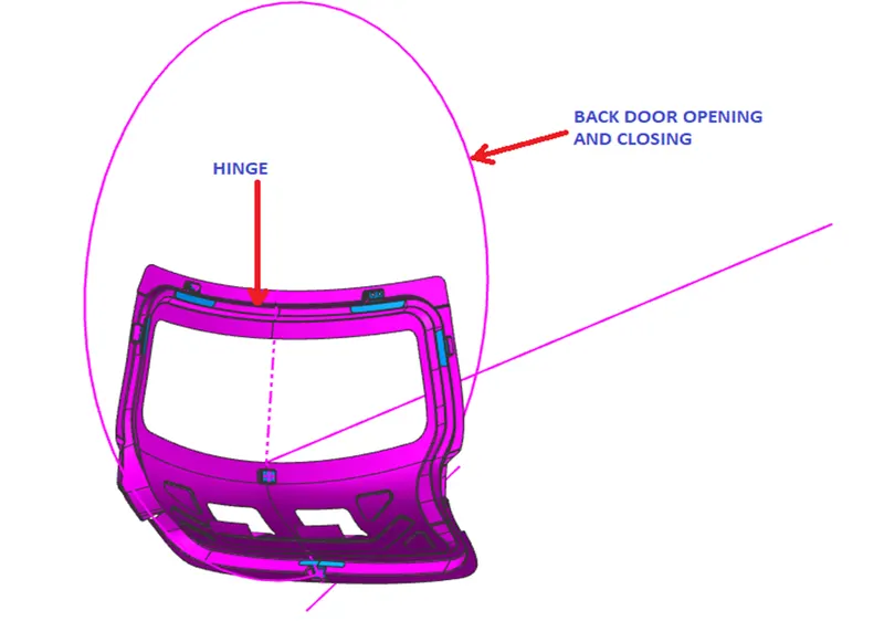
- To ensure proper closing and opening of the back door, the striker is placed in such a way that its trajectory is perpendicular to the hinge axis.
- Hinge axis is taken as center to draw a circle at the middle of the backdoor and latch is placed perpendicular to that circle.
- So here the positioning of latch totally depends upon hinge axis because when striker hits the latch system built in body compartment it must be tangentially perpendicular to the circle made from hinge axis or the moment it hits the latch system it inserted or get locked smoothly because slightest deviation may result in improper closing of back door.
- For the proper opening and closing of the back door, the striker should be positioned at a correct position. The striker should be perpendicular to the trajectory of the back door. The flanges are positioned at their respective positions. Then the line is drawn at a straight. Now the trajectory is derived from the hinge axis and the center distance from the striker.
10. BLEND RADIUS
- All the corner should be blend in corner to avoid the sharp edges.
- Minimum blend radius can be taken as ‘3T’. Where ‘T’ is taken as thickness of material.
DESIGNING OF TOP MOUNTED BACK DOOR
- OUTER PANEL OF BACK DOOR
- INNER PANEL OF BACK DOOR
1. OUTER PANEL OF BACK DOOR
Outer panel is outer part of the back door, if we see from the outside of the car. The outer panel give the outer look of the car. Outer panel is attached with the inner panel by hemming process. The main function of outer panel is to cover the boot of car from the backdoor. Thickness of outer panel is taken 0.75mm. It is created in two part as outer panel upper and outer panel lower.
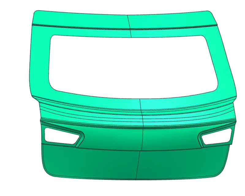
IMPROVE STYLING SURFACE
- Create one assembly file and add the given styling surface by name of body part or igs file.
- Improve the given surface radius, over lapping, gaps etc.
- To improve the surface, hide the defected surface, apply bridge curve command where necessary and after that joined the surface and bridge curve by through curve mesh or studio surface.
- In corner, apply extend sheet and after that go through trim and extend command and then apply face blend or edges blend there, whichever is required.
- After improving all surface area, sew all the part and save it.
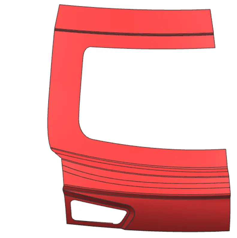
DESIGN OF OUTER PANEL UPPER
- Create two new part file name as outer panel upper.
- Use wave geometry linker to link the body part in outer panel upper file.
- Sew all the part.
- Offset the surface of 2.65mm (0.75+0.2+0.75+0.2+0.75mm) for hemming.
- Apply offset curve in face command of 10mm in offset surface.
- Apply tool direction line.
- Apply law extension on wave geometry linker surface in 90°
- Use face blend command in three face, and create hemming in outer surface.
- Apply mirror geometry and sew both part.
- Apply curve on surface in corner for giving relief in required surface, then trim the surface.
- Apply edge blend or face blend to avoid the sharp edges in corner.
- Thicken the outer panel about of 0.75mm.
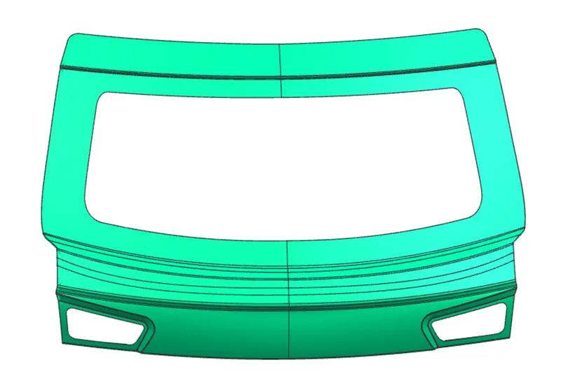
DESIGN OF OUTER PANEL LOWER
- Create two new part file name as outer panel lower.
- Use wave geometry linker to link the body part in outer panel lower file.
- Sew all the part.
- Offset the surface of 2.65mm (0.75+0.2+0.75+0.2+0.75mm) for hemming.
- Apply offset curve in face command of 10mm in offset surface.
- Apply tool direction line.
- Apply law extension on wave geometry linker surface in 90°
- Use face blend command in three face, and create hemming in outer surface.
- Apply mirror geometry and sew both part.
- Apply curve on surface in corner for giving relief in required surface, then trim the surface.
- Apply edge blend or face blend to avoid the sharp edges in corner.
- Thicken the outer panel about of 0.75mm.
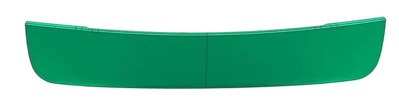
2. INNER PANEL OF BACK DOOR
Inner panel is internal part of the back door, if we see from the outside of the car. It is the most important component of the back door. All the reinforcement is attached on the inner panel of the back door. So, emboss is created on the inner panel for mounting these reinforcement. Inner panel is attached with the outer panel by hemming process. This compartment is used to strengthening the door assembly. Designed with consideration of given outer panel and followed with creating of embosses, mounting brackets and necessary reinforcement. Embosses are given to make the inner panel stiffer and good endurance while crash. It is created in Y shape to allow the force to flow and get dissipated outside and hence to protect the vehicle occupants.
DESIGN OF INNER PANEL
A. INNER FLANGE
- Create new file name as inner panel.
- Apply wave geometry linker to link the body part surface.
- Apply offset curve in face and trim the surface.
- Offset the surface and apply bridge curve and make the surface smoother.
- Use through curve mesh command or studio surface and join the surface.
- Maintain the gap of inner panel to outer panel as of 1.5mm (0.75+0.75mm) by offset surface.
- Apply face blend or edge blend to avoid the sharp edges and corner.
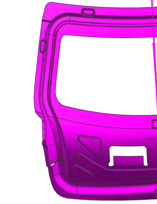
B. SHIELING FLANGE AND WIND SHIELD GLASS
- Use law extension command then apply trim and extend command and make the profile for shieling flange and sew all the surface.
- Use the sketch command and make the rectangular profile to make the wind shield glass.
- Apply law extension command for two times and maintain the dimension.
- Apply face blend or edge blend to avoid the sharp edges and corner.
- Use curve on surface or bridge curve for making profile smooth.
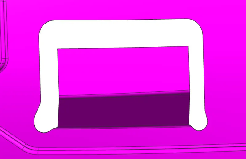
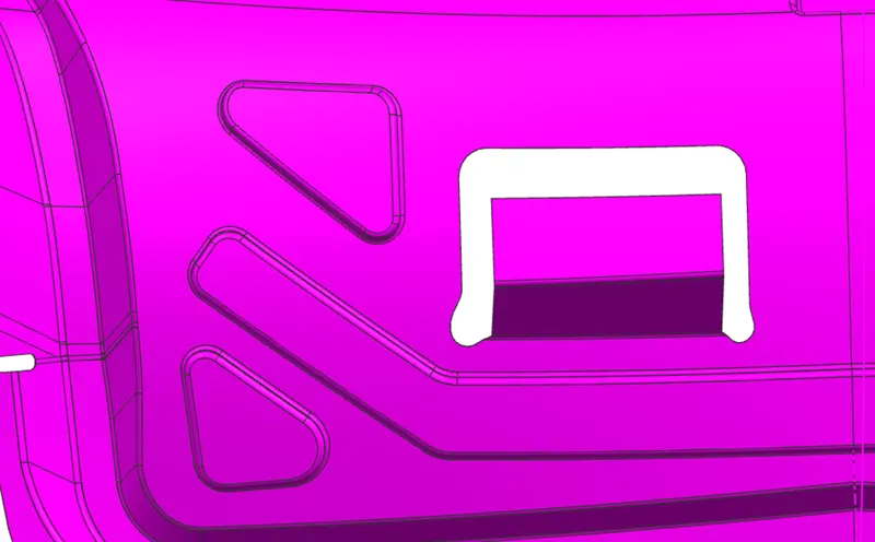
C. EMBOSS TO DIVERT THE FORCES
- Use sketch command parallel to surface and make the profile in ‘V’ or ‘Y’ shape to allow to divert the force.
- Apply emboss command in outer panel direction and give angle above then 7° and provide proper distance.
- Apply face blend or edge blend to avoid the sharp edges and corner.
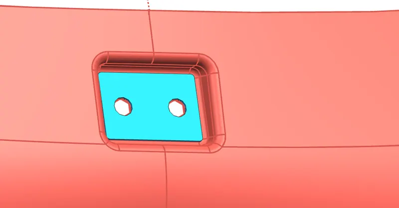
D. CREATE EMBOSS FOR HINGE REINFORCEMENT
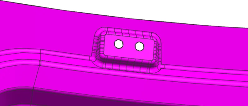
Hinge reinforcement emboss is created to mounted the hinge reinforcement. It is also created on inner panel as emboss to provide the strength to the inner panel. So, that it can withstand the load of back door and also help in impact force.

- Use sketch command and create datum plane parallel to surface and make line.
- Apply law extension command in 0° angle in proper dimension.
- After apply law extension command by using tool direction line to create flat surface and give angle above then 7°.
- Emboss is created in outer panel direction.
- Use trim and extend command to make hinge reinforcement.
- Apply the edge blend or face blend to avoid the sharp edges.
- Use sketch command on emboss surface and make circle in proper dimension.
- Use trim command to make the hole.
- Sew all the part and apply mirror geometry by using datum plane.
- Sew all the part.
E. GAS STAY MOUNTING REINFORCEMENT
Gas stay mounting reinforcement emboss is created to mounted the gas stay mounting reinforcement. It is also created on inner panel as emboss to provide the strength to the inner panel. So, that it can withstand the load of back door and also help in impact force.

- Use sketch command and create datum plane parallel to surface and make line.
- Apply law extension command in 0° angle in proper dimension.
- After apply law extension command by using tool direction line to create flat surface and give angle above then 7°.
- Emboss is created in outer panel direction.
- Use trim and extend command to make gas stay reinforcement.
- Apply the edge blend or face blend to avoid the sharp edges.
- Use sketch command on emboss surface and make circle in proper dimension.
- Use trim command to make the hole.
- Sew all the part and apply mirror geometry by using datum plane.
- Sew all the part.
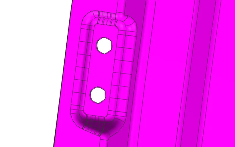
F. CREATE LATCH AND STRIKER POINT AND DIRECTION
- Create point in hole of hinge emboss.
- Use line command and make line by using these point.
- Make circle by applying coincident constraint through geometrical constraint as applying midpoint of line as center of circle.
- Make line perpendicular and tangent to circle for making the latch and striker reinforcement.
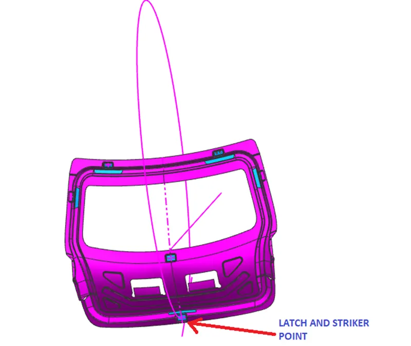
G. CREATE EMBOSS FOR LATCH AND STRIKER REINFORCEMENT
Latch and striker reinforcement emboss is created to mounted the latch and striker reinforcement. It is also created on inner panel as emboss to provide the strength to the inner panel. So, that it can withstand the load of back door and also help in impact force.
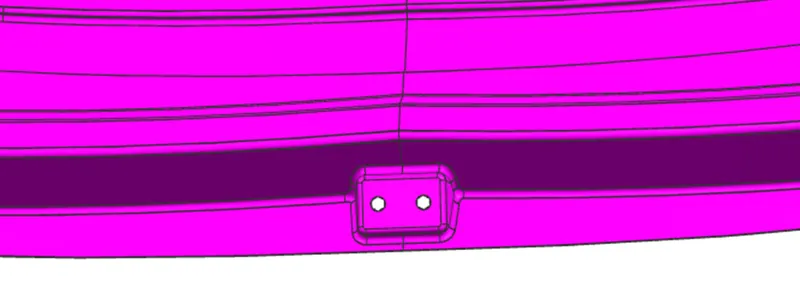
- Apply law extension command in perpendicular and tangent line in 0° angle and give the width dimension.
- Again apply the law extension command to create emboss surface for latch and striker reinforcement by giving angle above then 7°.
- Emboss is created in outer panel direction.
- Use trim and extend command on both surface.
- Apply the edges blend or face blend to avoid the sharp edges.
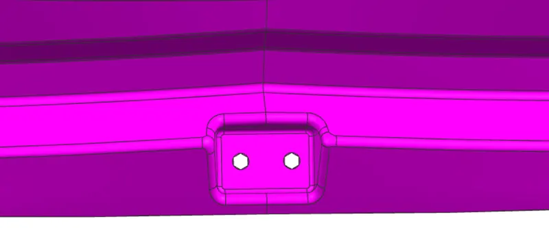
H. CREATE EMBOSS FOR WIPER MOUNTING REINFORCEMENT.
Wiper mounting reinforcement emboss is created to mounted the wiper mounting reinforcement. It is also created on inner panel as emboss to provide the strength to the inner panel. So, that it can withstand the load of back door and also help in impact force.
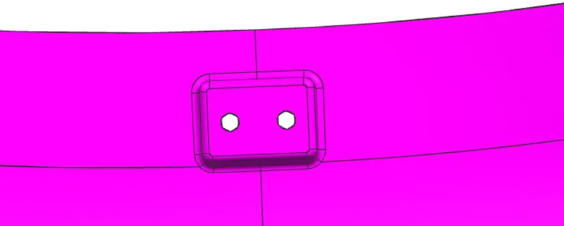
- Use sketch command and create datum plane parallel to surface and make line.
- Apply law extension command in 0° angle in proper dimension.
- After apply law extension command by using tool direction line to create flat surface and give angle above then 7°.
- Emboss is created in outer panel direction.
- Use trim and extend command to make wiper mounting reinforcement.
- Apply the edge blend or face blend to avoid the sharp edges.
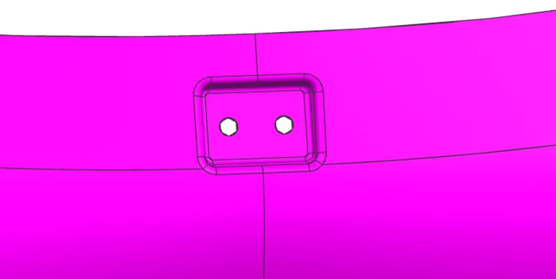
After complete the inner panel apply thicken command of 0.75mm in outer panel direction.
DIFFERENT REINFORCEMENT IN A BACK DOOR
Back door not only consist of outer panel and inner panel, it also consist of multiple reinforcement that provide strength and support to back door. These reinforcement is attached in the emboss surface of inner panel of backdoor. Reinforcement is given to the inner panel to minimize the impact of collision. Thickness of these reinforcement is 1.5mm. The reinforcement which is attached in the inner panel are-:
- Hinge reinforcement
- Gas stay mounting reinforcement
- Wiper mounting reinforcement
- Latch and striker reinforcement
1. HINGE REINFORCEMENT
Hinge reinforcement is giving an important role for opening and closing the back door in rotary movement. Hinge reinforcement is attached in given emboss of inner panel. It is fastened in the inner panel. The part should be strong enough to take the load of the back door and the forces act upon the back door. Generally two hinge reinforcement is placed in back door. Some times hinge is also placed outside of the car and cover by plastic component.
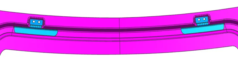
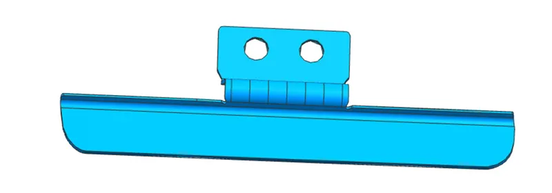
DESIGN OF HINGE REINFORCEMENT
- Create new file as name of hinge reinforcement in back door assembly and use wave geometry linker to create hinge reinforcement.
- Use bridge curve and curve on surface command in the corner.
- Trim the surface by using trim sheet command.
- Apply thicken command of 1.5mm.
- Apply mirror geometry by using datum plane to create two hinge in inner panel.
2. GAS STAY MOUNTING REINFORCEMENT
A gas stay is a type of spring that, unlike a typical mechanical spring that relies on elastic deformation, uses compressed gas contained within an enclosed cylinder sealed by a sliding piston to pneumatically store potential energy and withstand external force applied parallel to the direction of the piston shaft. It takes minimum efforts to lift.
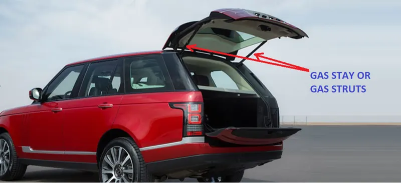
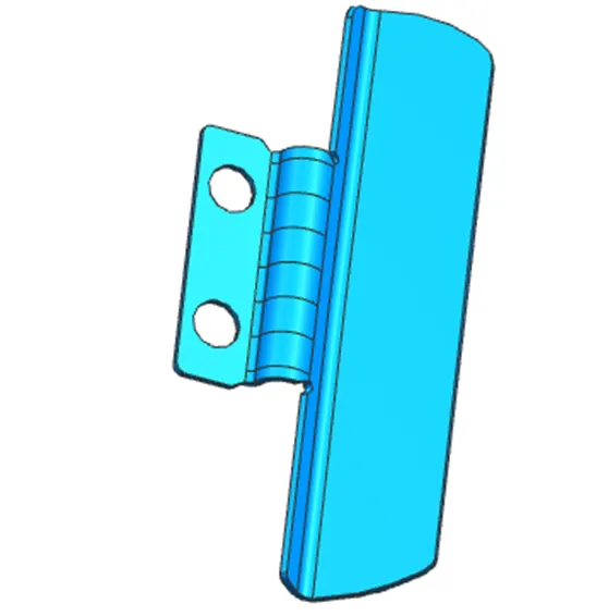
So, to mount the gas stay in inner panel, gas stay mounting reinforcement is created. This gas stay mounting reinforcement is attached in emboss of inner panel with the help of gas stay socket.
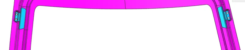
DESIGN OF GAS STAY REINFORCEMENT
- Create new file as name of gas stay reinforcement in back door assembly and use wave geometry linker to create gas stay mounting reinforcement.
- Use bridge curve and curve on surface command in the corner.
- Trim the surface by using trim sheet command.
- Apply thicken command of 1.5mm.
- Apply mirror geometry by using datum plane to create two gas stay mounting in inner panel.
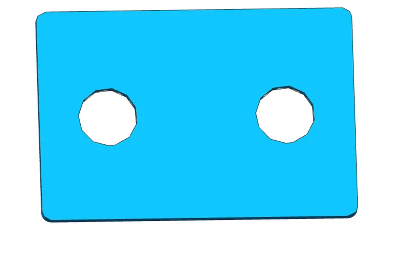
3. WIPER MOUNTING REINFORCEMENT
Wiper is use to wipe of the dust of sand, leaves etc. in back door’s glass. It is also use to wipe off the water which is stick on back door’s glass in rainy season or by any condition. Wiper mounting reinforcement give very important role for rear visibility area to the driver by cleaning the back door glass. It is placed in the middle of backdoor in inner panel given cavity and for other accessories. it is attached in inner panel by fastening.
DESIGN OF WIPER MOUNTING REINFORCEMENT
- Create new file as name of wiper mounting reinforcement in back door assembly and use wave geometry linker to create wiper mounting reinforcement.
- Use bridge curve and curve on surface command in the corner.
- Trim the surface by using trim sheet command.
- Apply thicken command of 1.5mm.
4. LATCH AND STRIKER REINFORCEMENT
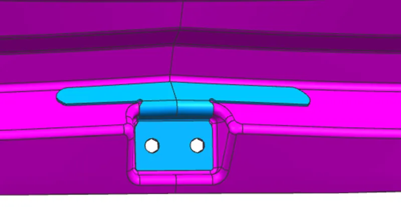
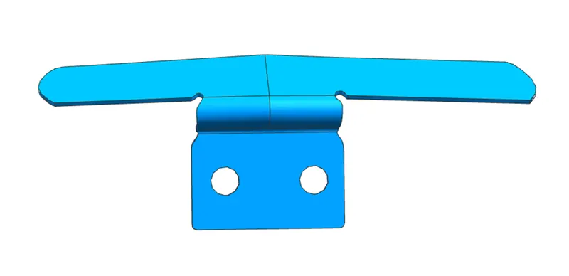
Latch and striker is attached in inner panel of back door cavity by fastening. It is placed in bottom side of back door. It is located in latch striker point which is created by making circle using center as middle point of line of hinge axis. It provide locking of back door properly. In some cars, sensor is also attached in latch and striker reinforcement.
DESIGN OF LATCH AND STRIKER REINFORCEMENT
- Create new file as name of latch and striker reinforcement in back door assembly and use wave geometry linker to create latch and striker reinforcement.
- Use bridge curve and curve on surface command in the corner.
- Trim the surface by using trim sheet command.
- Apply thicken command of 1.5mm.
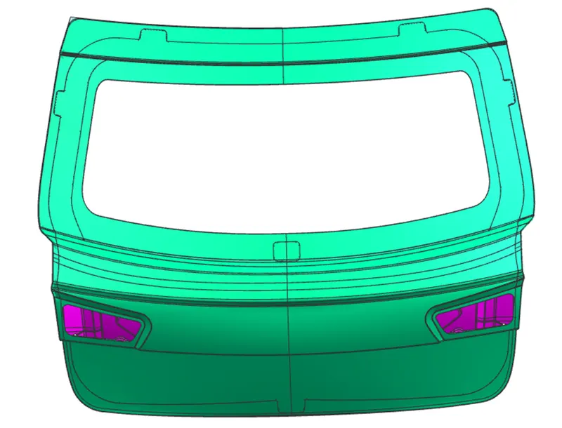
COMPLETE ASSEMBLY OF BACK DOOR
ANALYSIS IN BACK DOOR DESIGN
DRAFT ANALYSIS
The draft analysis technique is used to analyze our part model, whether it is manufactured on the proper draft angle applied. A Draft Angle describes the amount of taper for molded or cast parts perpendicular to the parting line or vertical axis. No parts can be ejected from the tool if it is having a straight 90-degree profile from its base surface. A small draft angle is provided to each and every area of the component in order to get easy removal of the component from the tool.
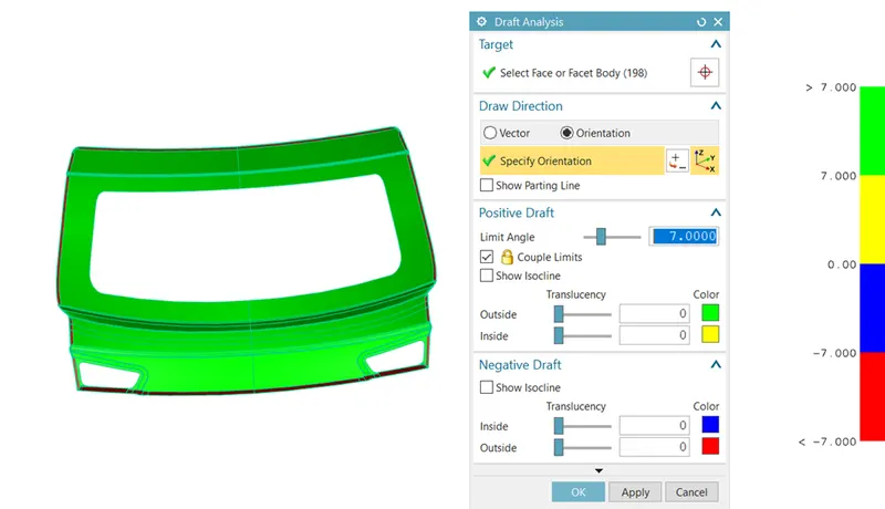
1. BACK DOOR OUTER PANEL UPPER
Applied the draft analysis on outer panel upper at an angle of 7 degree. For that click on draft analysis, then click on face or facet body option and select the back door outer panel upper. Enter the value of limit angle then select specify vector. Select the direction.
- The green and yellow portion is shown the part is created in proper limit angle and it is satisfied.
- The blue and red part is shown that the part is created not in proper limit angle and satisfied or not good. So, redesign the part for make it into a full green colour.
2. BACK DOOR OUTER PANEL LOWER
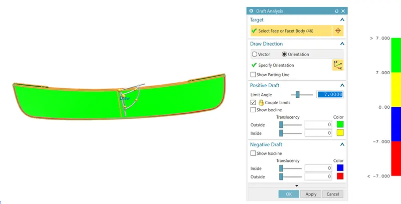
Applied the draft analysis on outer panel lower at an angle of 7 degree. For that click on draft analysis, then click on face or facet body option and select the back door outer panel lower. Enter the value of limit angle then select specify vector. Select the direction.
- The green and yellow portion is shown the part is created in proper limit angle and it is satisfied.
- The blue and red part is shown that the part is created not in proper limit angle and satisfied or not good. So, redesign the part for make it into a full green colour.
3. BACK DOOR INNER PANEL
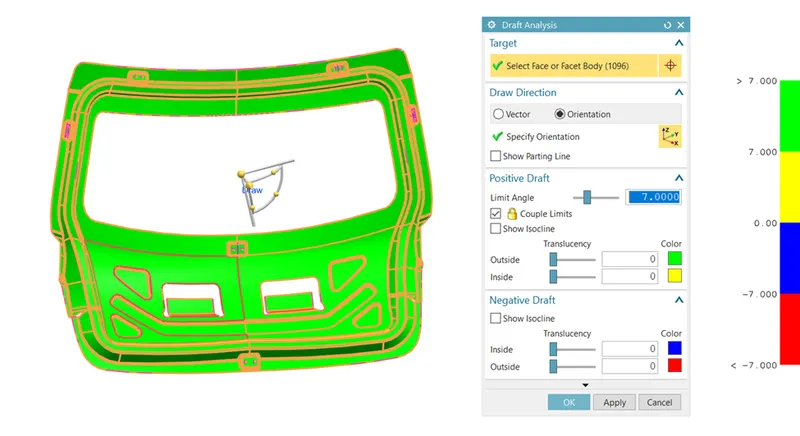
Applied the draft analysis on back door inner panel at an angle of 7 degree. For that click on draft analysis, then click on face or facet body option and select the back door inner panel. Enter the value of limit angle then select specify vector. Select the direction.
- The green and yellow portion is shown the part is created in proper limit angle and it is satisfied.
- The blue and red part is shown that the part is created not in proper limit angle and satisfied or not good. So, redesign the part for make it into a full green colour.
4. BACK DOOR HINGE REINFORCEMENT
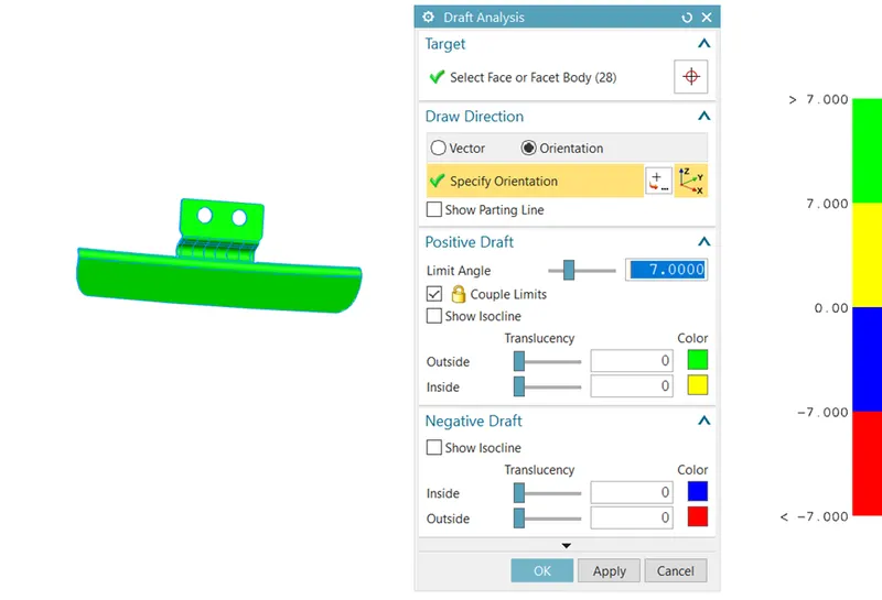
Applied the draft analysis on back door hinge reinforcement at an angle of 7 degree. For that click on draft analysis, then click on face or facet body option and select the backdoor hinge reinforcement. Enter the value of limit angle then select specify vector. Select the direction.
- The green and yellow portion is shown the part is created in proper limit angle and it is satisfied.
- The blue and red part is shown that the part is created not in proper limit angle and satisfied or not good. So, redesign the part for make it into a full green colour.
5. BACK DOOR GAS STAY MOUNTING REINFORCEMENT
Applied the draft analysis on back door gas stay mounting reinforcement
at an angle of 7 degree. For that click on draft analysis, then click on face or facet body option and select the back door gas stay mounting reinforcement. Enter the value of limit angle then select specify vector. Select the direction.
- The green and yellow portion is shown the part is created in proper limit angle and it is satisfied.
- The blue and red part is shown that the part is created not in proper limit angle and satisfied or not good. So, redesign the part for make it into a full green colour.
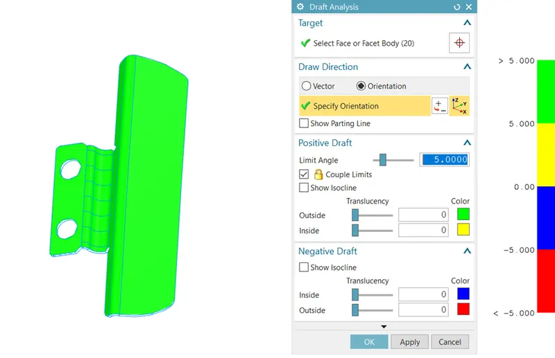
6. BACK DOOR LATCH AND STRIKER REINFORCEMENT
Applied the draft analysis on back door latch and striker reinforcement
at an angle of 7 degree. For that click on draft analysis, then click on face or facet body option and select the back door latch and striker reinforcement. Enter the value of limit angle then select specify vector. Select the direction.
- The green and yellow portion is shown the part is created in proper limit angle and it is satisfied.
- The blue and red part is shown that the part is created not in proper limit angle and satisfied or not good. So, redesign the part for make it into a full green colour.
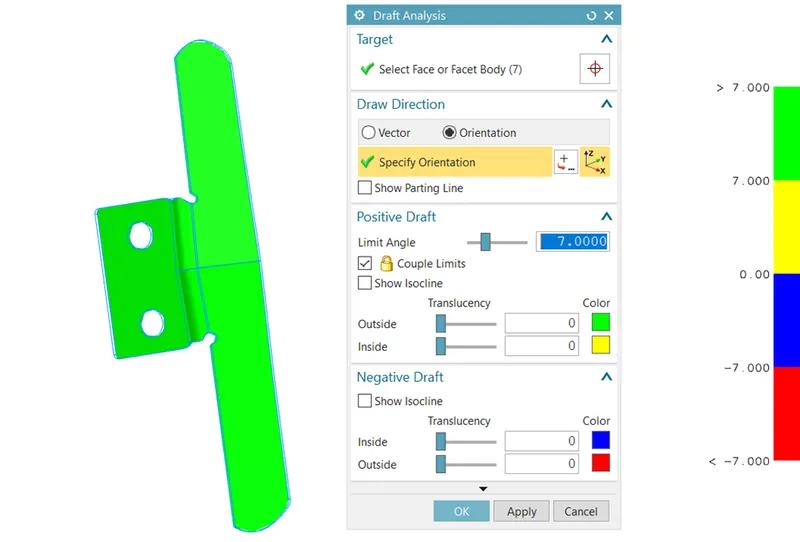
7. BACK DOOR WIPER MOUNTING REINFORCEMENT
Applied the draft analysis on back door wiper mounting reinforcement
at an angle of 7 degree. For that click on draft analysis, then click on face or facet body option and select the back door wiper mounting reinforcement. Enter the value of limit angle then select specify vector. Select the direction.
- The green and yellow portion is shown the part is created in proper limit angle and it is satisfied.
- The blue and red part is shown that the part is created not in proper limit angle and satisfied or not good. So, redesign the part for make it into a full green colour.
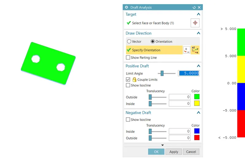
CONCLUSION
Back door is very important to protect the car as well as for locking luggage and other goods. So, we should follow all consideration while designing of back door and after designing, draft analysis is done on surface for knowing whether surface is created within further limit. If it not under limit, we should designed it again and complete the back door design in safely manner.