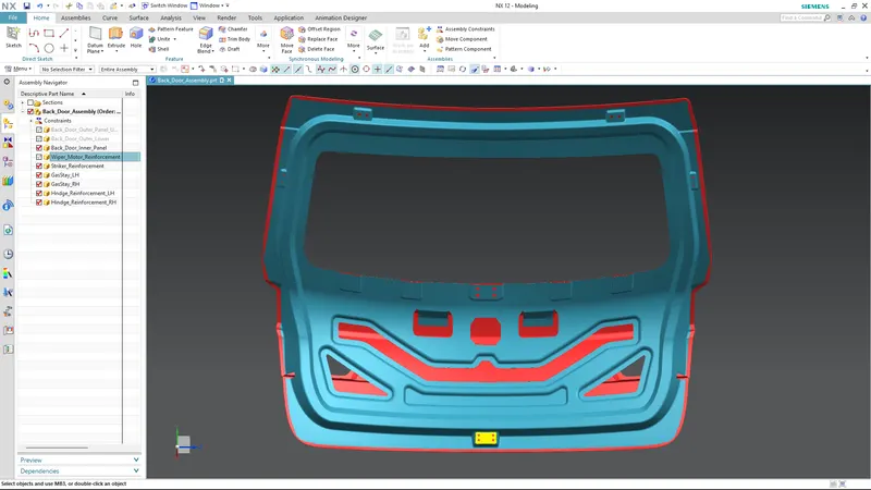
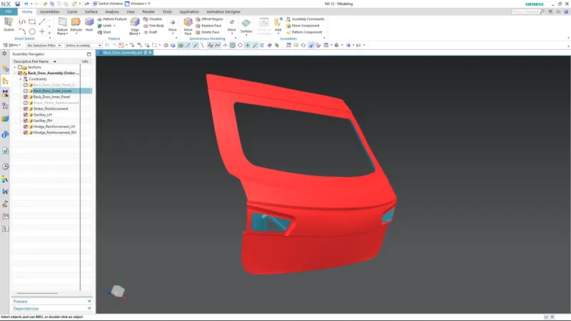
Design of backdoor
Back Door
Aim:
- To design a back door of a car by using the given styling surface.
- To provide necessary reinforcement and embosses.
Introduction:
The backdoor or tailgate is the rear most part of the automobile which opens upwards, downwards or sideways to give access to the luggage space or seating area. In most of the cars the backdoor opens upwards. It is hinged to the roof and a gas stay support fixed at the body side outer for keeping the backdoor in open position. In most of the cars, these back doors are operated with the help of gas stay which in turn reduces the effort required to lift open the door. Some luxury cars have powered backdoor which in turn is driven by an electric motor. A car back door which is consist of Inner panel, Outer panel. Basically, the car parts are made of Steel or Aluminium based on the budget of the car. Steel parts are stamped and we cannot vary the thickness of material, so we need to add a greater number of parts and which increases the weight of the car. But the using of aluminium can improve the strength and we can also vary the thickness of the material so that we can avoid/reduce the reinforcements as compared to steel. The main advantage of aluminium over steel is that the density of aluminium is very less as compared to steel so it reduces the overall weight of the car. So now a days most of the car manufacturers are trying to use Aluminium instead of Steel and they reduce the number of parts and weight of the car drastically.
Draft angles present one of the key aspects of designing plastic parts to for the injection molding process. Draft angles or tapers on injection molded plastic parts facilitate part ejections from the mold. Unlike 3D printed parts or machined parts, injection molded parts must consider how the parts will be removed from the mold. Usually a mold involves a cavity side which is the hollow side, and a core side which is the opposite side.
Before the mold opens, the resin has already begun to cool. Cooling causes the resin to shrink. Shrinkage causes the resin to tighten around the core. When the mold opens, the core and cavity separate. The part sticks to the core side of the mold.
Check for Connectivity using Join Command :
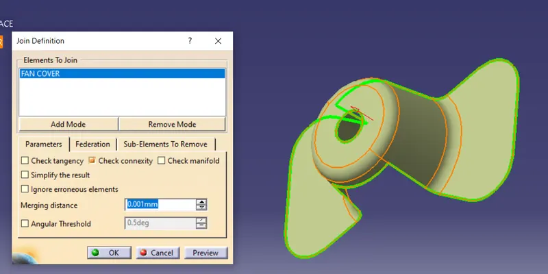
As you can see it is continous,now we will see if the faces are perpendicular to the tooling axis as shown below :
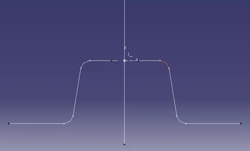
As you can see the non parallel sides can be problem during moulding therefore they need to be checked.This is done by creating the bisecting line as shown below :
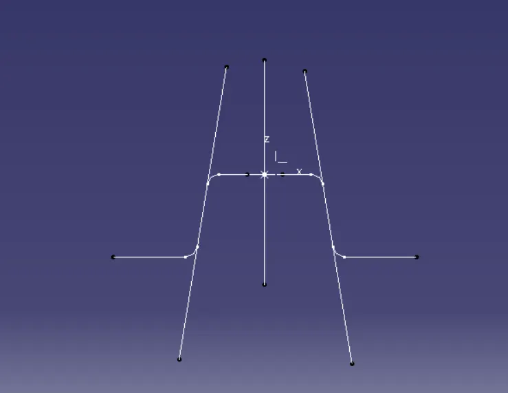
Now creating the tooling axis in the y axis we get :
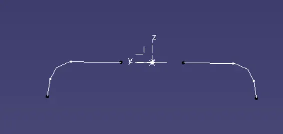
Creating the bisecting line we get the following :
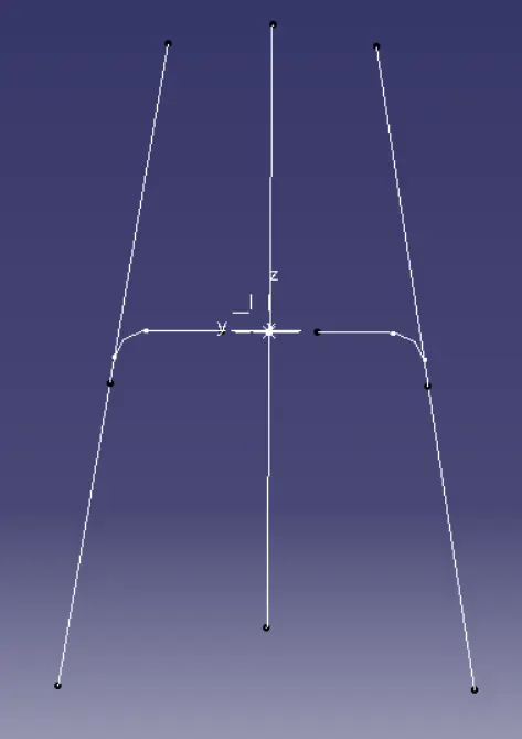
Now using the bisecting line tool we will bisect these two to get a single line as shown below :
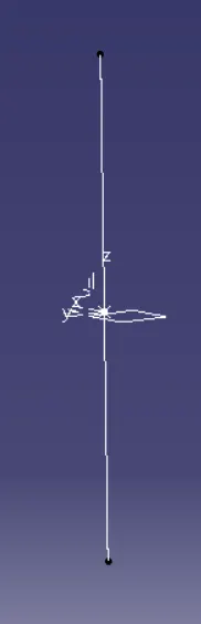
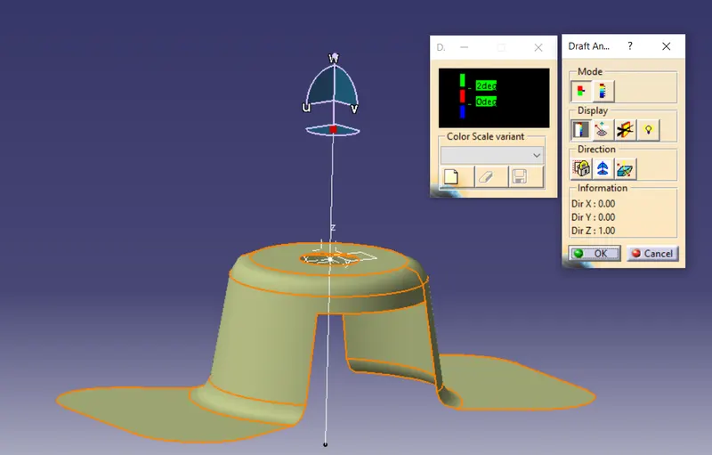
Now we will use feature draft analysis as shown below :
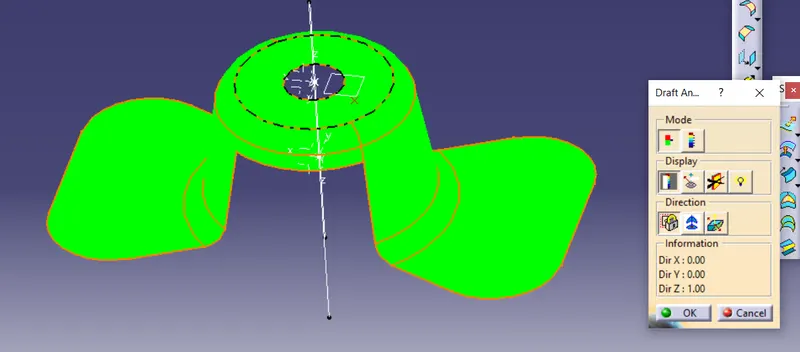
If we increase the draft to 10 degrees we get :
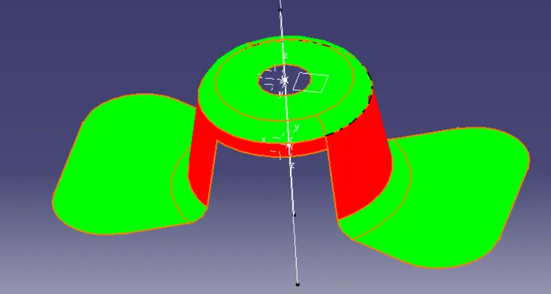
Red meaning the draft angle is between 10 and 0 degrees.
There are 3 types of backdoors based on working condition.
- Top mounted door
- Side mounted door
- Bottom/split type of door
- Top mounted door.
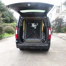
- Side mounted door
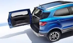
- Bottom/split type of door
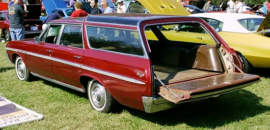
Types of mechanisms for Backdoor
1. Gas stays type:
Gas stay types backdoor/liftgate/tailgate is an ideal and most commonly used tailgate mechanism from lower segment car to luxury car segment. The ideal components of tailgate consist of a hinge, door, gas stay and some rubber beadings for sealing of door.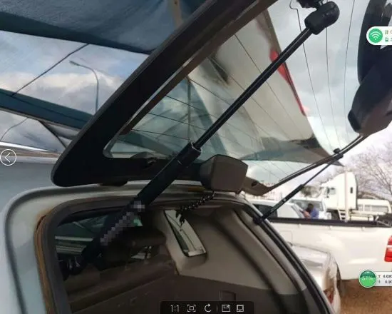
2. Powered lift system:
Power trunk lid system is another sophisticated way of trunk/liftgate opening mechanism which is to automatically open and close of the trunk/liftgate and release of the latch by the touch of a button. The following image shows the component as used in the powered trunk/back door lift system. Powered trunk lift system consists of a power latch, anti-pinch switch, PTG ass’y, PTG main switch. When the switch is pressed in the compartment or outside the power latch releases the latch and the entire backdoor is opened. The anti-pinch switch is located in order to avoid accidental hand insertion during the operation of the door.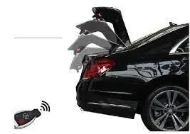
Different Sheetmetal processes used for manufacturing the Backdoor
- Blanking:
Blanking is a metal fabricating process, during which a metal workpiece is removed from the primary metal strip or sheet when it is punched. The control of the quality by the punch and die clearance. The ability to produce holes of varying shapes – quickly. Blank is the required product of the operation and the metal left behind is considered as a waste.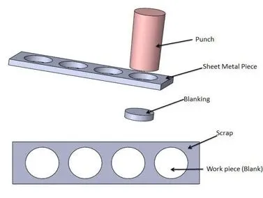
- Punching:
It is similar to blanking only the main difference is that, the hole is the required product and the material punched out from the hole is considered as a waste.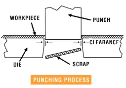
- Deep drawing :
It is a sheet metal forming process in which a sheet metal blank is radially drawn into a forming die by the mechanical action of a punch. It is thus a shape transformation process with material retention. The process is considered "deep" drawing when the depth of the drawn part exceeds its diameter.
Deep drawing processes are divided into three types:
* Deep drawing with tools
*Deep drawing with active means
*Deep drawing with active energy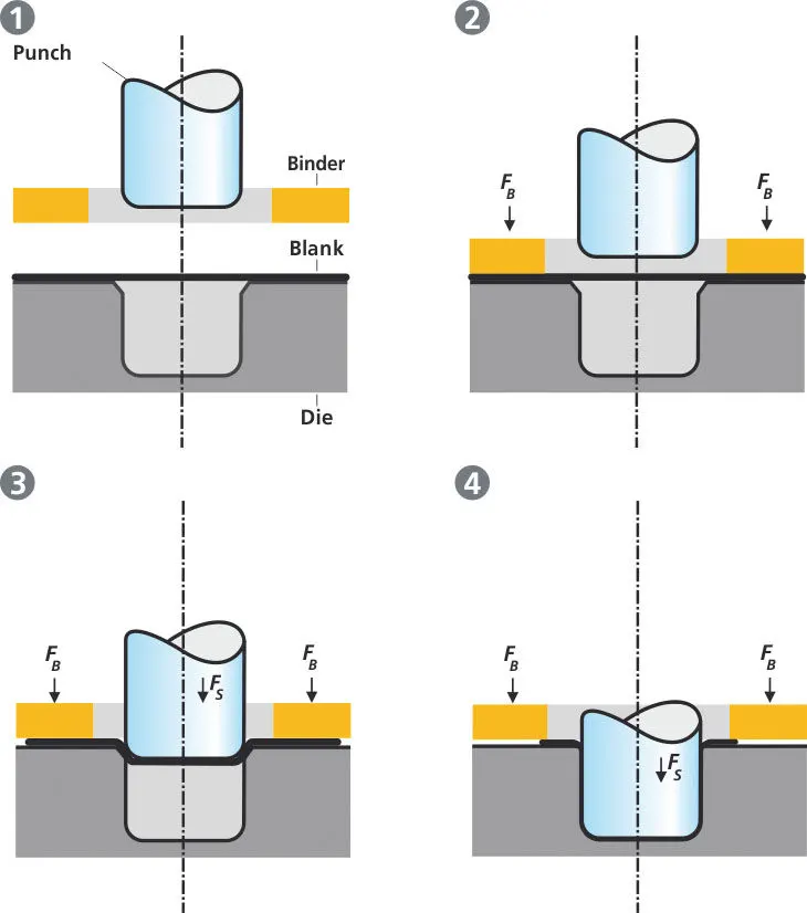
- Trimming:
Trimming is a manufacturing process that is used as a finishing operation for forged parts, in order to remove flash. Most often it is desirable to perform this operation while the work is still hot for maximum efficiency, therefore it is usually incorporated into the larger production process.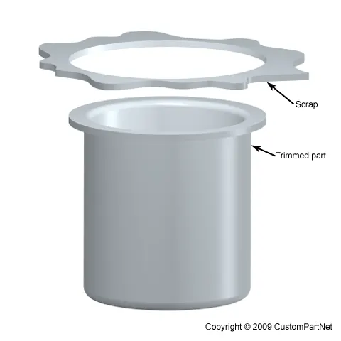
- Embossing:
Embossing is a metal forming process for producing raised or sunken designs or relief in sheet materials by means of matched male and female roller dies, theoretically with no change in metal thickness or by-passing sheet or a strip of metal between rolls of the desired pattern. Metal sheet is drawn through the male and female roller dies producing a pattern or design on the metal sheet. Depending on the roller dies used, different patterns can be produced on the metal sheet.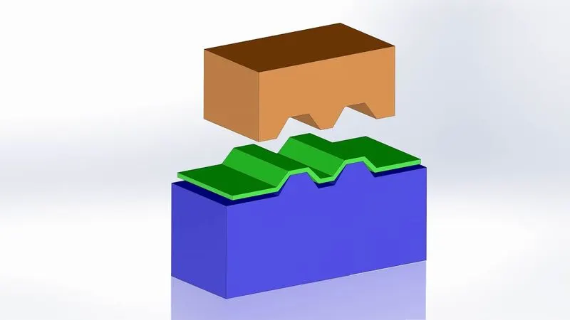
- Hemming:
Hemming is a forming operation in which the edges of the sheet are folded or folded over another part in order to achieve a tight fit. Normally hemming operations are used to connect parts together, to improve the appearance of a part and to reinforce part edges.In car part production, hemming is used in assembly as a secondary operation after deep drawing, trimming and flanging operations to join two sheet metal parts (outer and inner) together. Typical parts for this type of assembly are hoods, doors, trunk lids and fenders.
There are various types of hemming operations:
1) Conventional die hemming: In conventional die hemming, the flange is folded over the entire length with a hemming tool.
2) Roll hemming: In roll hemming, the hemming roller is guided by an industrial robot to form the flange.
3) Open Hem: A Hem has a full round feature and a return flange. In open hem bend angle is equal to 180 degrees.
4) Tear drop Hem: In tear drop hem the bend angle is greater than 180 degrees.
5) Closed Hem: Hems without any inside radius are called as closed hem. Closed hems are not recommended if the hem geometry is to be painted or if the material used is SST or Aluminium.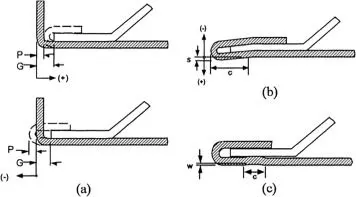
Design of outer panel:
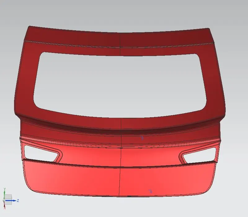
The outer panel of the back door is similar to other BIW components where it is the aesthetic part of a vehicle. The coating provided is of multi-stage which has the property of scratch resistance, rust prevention and smooth and attractive finishes. The outer panel also has the provisions for the tail lamp, rear fog lamp and also has the provision for licence plate mountings. Most of the hatchback cars have the provision for wiper motor. Given surfaces has to be repaired according to the smoothness. After repairing the surfaces, the door is divided into two parts as outer panel upper and outer panel lower.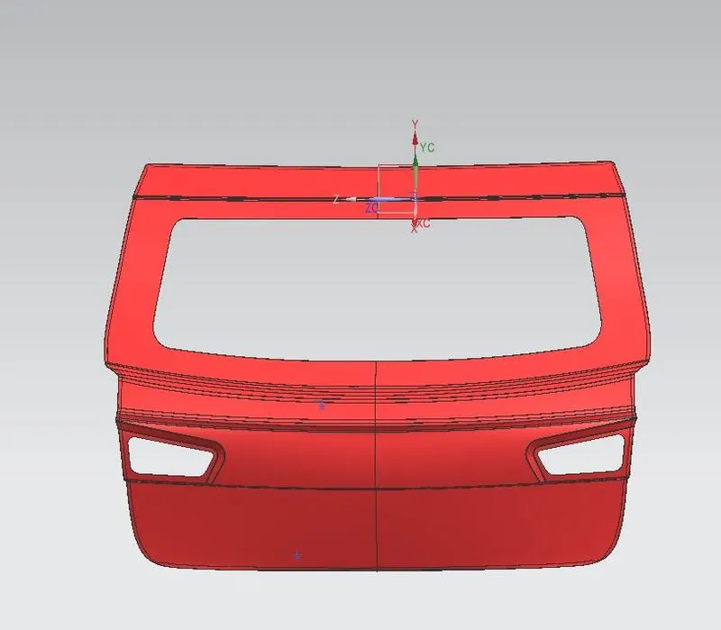
Design of Inner panel:
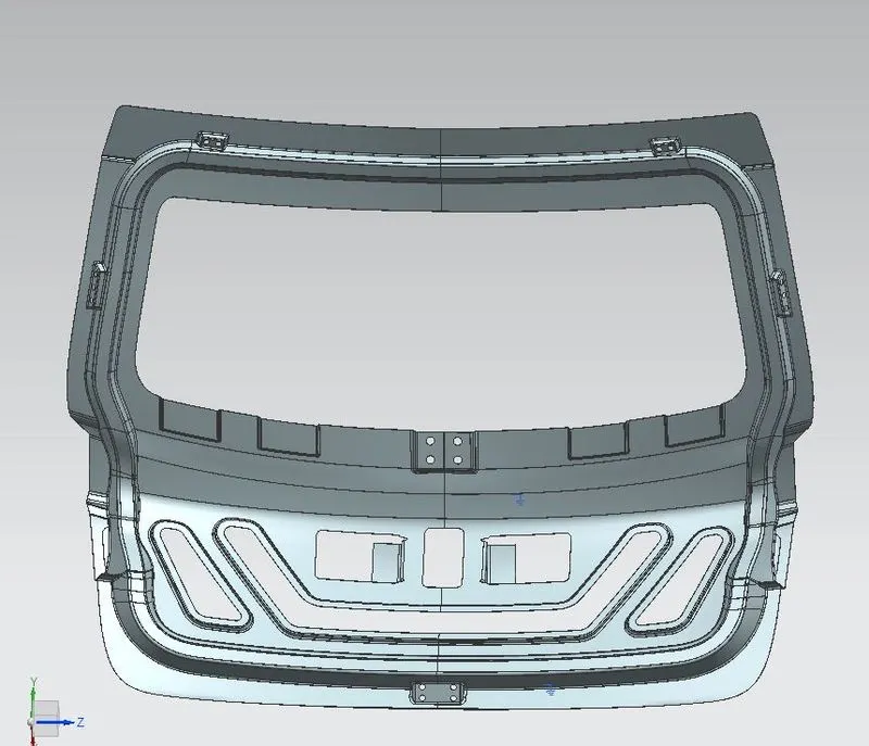
The inner door panel is a component which is used for strengthening the door assembly and it is one of the most important components on which all accessories are mounted like hinges, glass guide channel, moulded trim, latch etc. The possible method is the integration method. In the integration method, the part is stamped out of a single blank. This reduces the number of tools needed; the assembly cost and eliminates any fit ability problem. The inner panel was designed by offsetting the given class A surface as per the given master section. The inner panel consists of Embosses and Mastics.
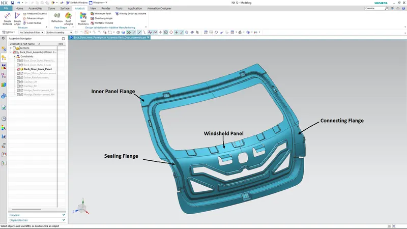
First, we need to create the Tooling direction for the Deep drawing operation. It shows that all the operations like embossing is done by considering this vector direction and it will help in manufacturing the part. After that we have to create Sealing Flange by offsetting the outer panel to the specific distance.
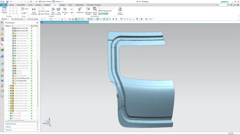
Then we will be creating the Back door inner panel flange by offsetting the outer surface at a distance considering the sheet thickness and thickening direction. Then created the connecting flange to join the inner panel and sealing flange. Then for the windshield panel mounting, windshield panel is created and joined with sealing flange.
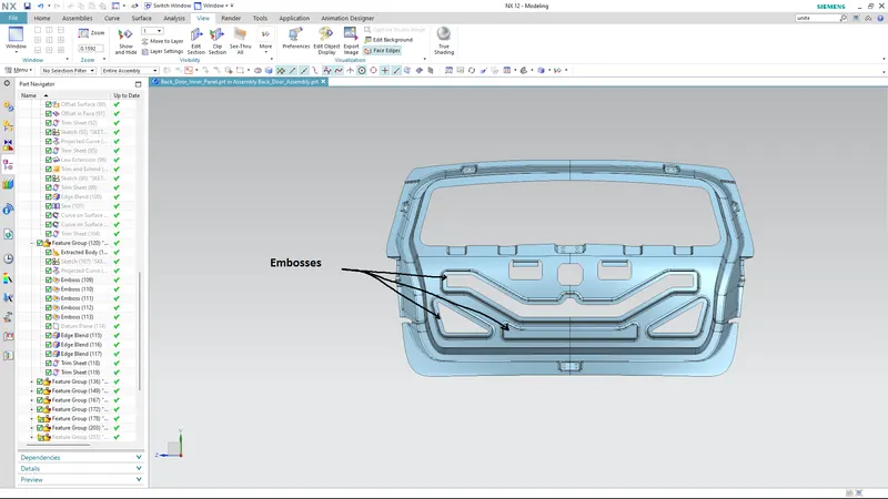
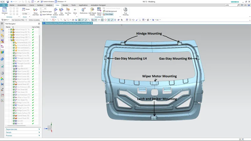
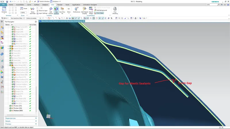
Then to improve the strength of the inner panel and to reduce the weight 'Y' type emboss and other cut-outs are created. Also, for Latch and Stricker mounting cut-out is created. This cut-out is also done on other side of the inner panel to maintain the centre of gravity of the Back door. The inner panel is mainly fixed to the outer panel by the process of hemming but still there will be rattling noise. So, to avoid those extensions are created in the inner panel which is fixed to the outer panel by applying mastic seal. While designing make sure to give 4-5 mm distance from the outer panel so that mastic seal can be applied in that area.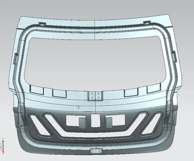
Design of reinforcements:
Reinforcements basically strengths or increases the mechanical properties of the material. The hinge reinforcements are provided so as to increases the strength during bolting.
The different types of reinforcements used here are
- Hinge reinforcement
- Gas stay reinforcement
- Wiper motor reinforcement
- Latch/striker reinforcement
Hinge Reinforcement: Hinges are the essential, that allows doors to pivot on one edged as open as they open and close. They are found on virtually all doors. It is a mechanical bearing that connects two solid objects, typically allowing only a limited angle of rotation between them.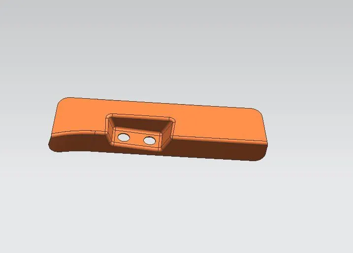
Gas stay reinforcement: It is used to lift up the Tail gate. There are two types of Gas stay reinforcements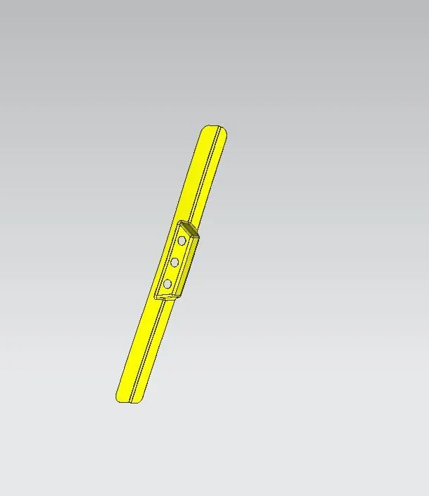
Wiper motor reinforcement: A small electric motor which is mounted on the wiper motor reinforcement in the rear tail gate. It used to clean the rear wind shield for clear visibility.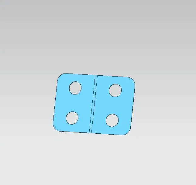
Latch and striker Reinforcement: Using the axis of the hinge, a circle is drawn at the middle of the back door and the latch is placed perpendicular to the circle.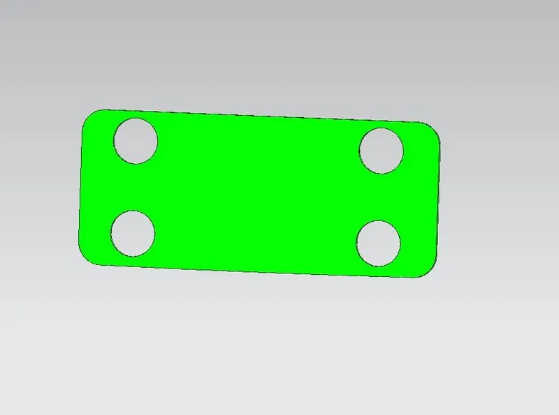
Design of Hemming:
Hemming is a sheet metal forming process in which sheets are joined by bending it usually to 180°. Automotive body panels and automotive parts such as deck-lids, trunk-lids, doors, hoods and tailgates are formed by hemming process. Hemming is a forming operation in which the edges of the sheet are folded or folded over another part in order to achieve a tight fit. Normally hemming operations are used to connect parts together to improve the appearance of a part and to reinforce part edges. Hemming is used in assembly as a secondary operation after deep drawing, trimming and flanging operation to join two sheet metal parts (outer and inner) together. Relief is provided at some position which helps to control sheet metal material behaviour and to prevent unwanted deformation during unbend operations.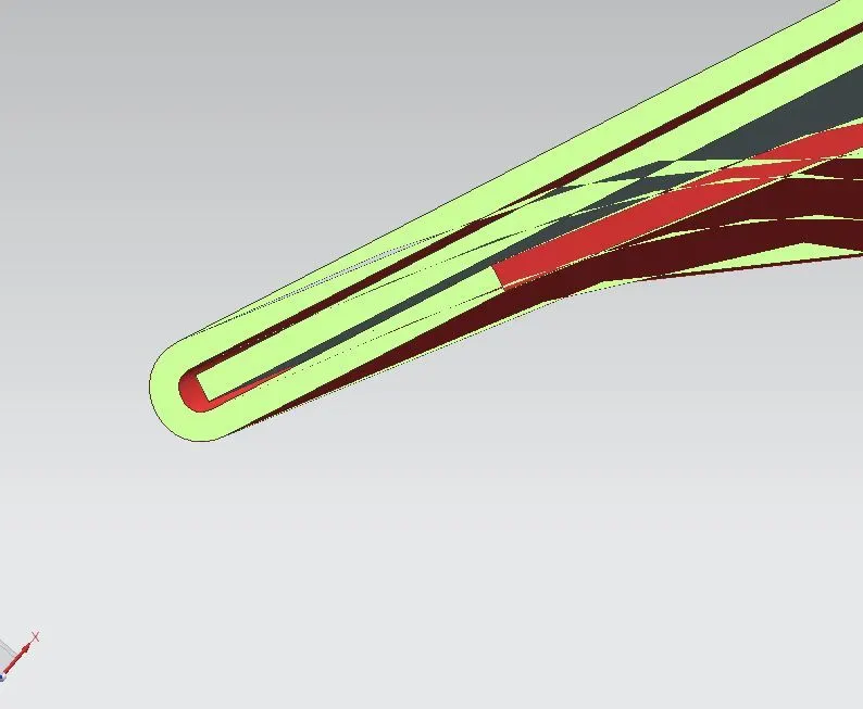
Draft analysis:
Every part like sheet metal parts which are generated from a Press Tool or some forming tools, may be the plastic parts which generally come out from the plastic moulds and maybe the casting parts, all such kind of parts required some drafted face on the surfaces which are parallel to the tooling direction. If we don't provide drafts on the surface then it will stick to the mould surface and whenever the mould is in motion, they will destroy the surfaces or also reduced the finishing of surfaces. Draft is used for providing angles or tapers on product features such as walls, ribs, posts, and bosses that lie parallel to the direction of release from the mould ease’s part ejection. Draught angles are designed in such a way that they will assist depart rejection. By doing so we have a reduced cycle time and improved productivity. Draft value for a particular part is mostly decided by the material used for making it. Generally, for the plastic materials draught value you are very from 0.25 degree to 2 degree.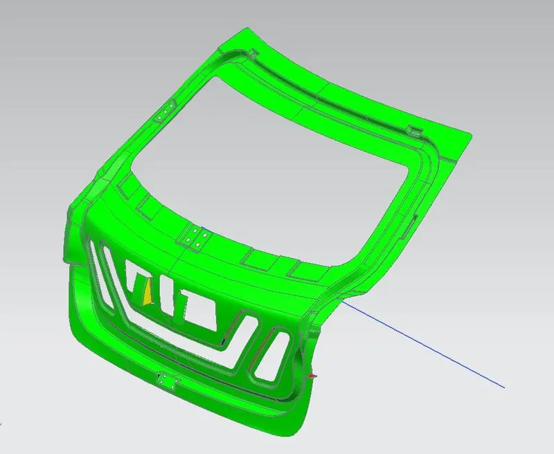
Assembly Images: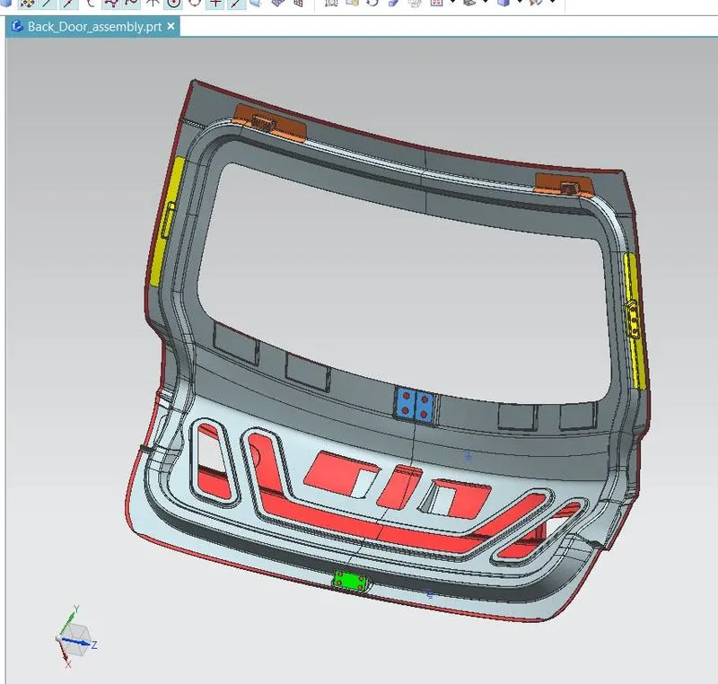
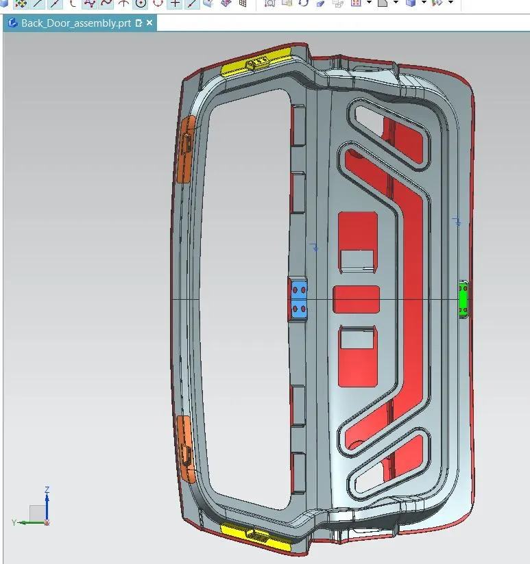
A back door or tailgate is the rear side of a car which gives access for the boot space to store luggage, spare wheel, etc. These doors can be operated manually or electric powered.
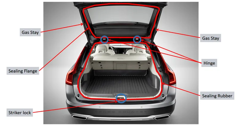
The backdoor consists of the following basic components:
- Backdoor Inner Panel
- Backdoor Outer Panel Upper
- Backdoor Outer Panel Lower
- Hindge Reinforcements
- Gas-Stay Reinforcements
- Latch and Striker Reinforcement
- Wiper Motor reinforcement
Types of Backdoor:
1. Top Mounted Door
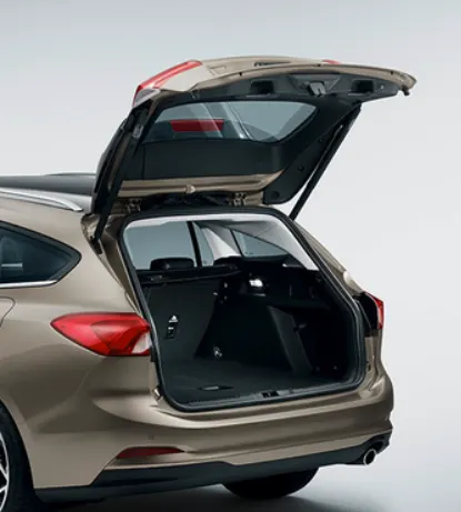
2. Side Mounted Door
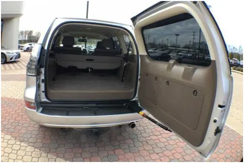
3. Bottom Door
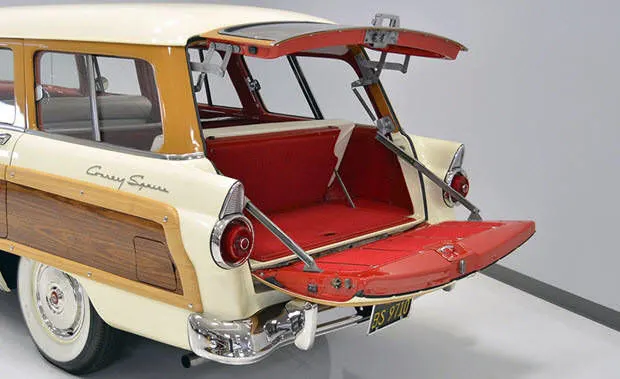
Repairing the Styling Syling Surface:
There were some irregularities in the given surface therefore, the surface was repaired and smoothen up. The final surface of the backdoor is as shown in the figure.
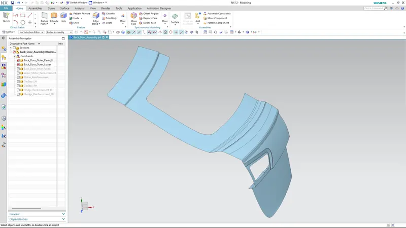

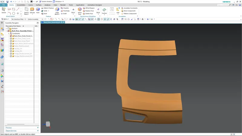
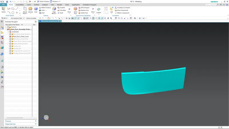
After repairing the surafces, the door is divided into two parts viz. Door Outer Upper and Door Outer Lower.
Desing Procedure:
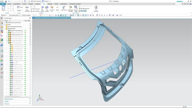
1. Tooling Direction
A tooling direction was set for the deep drawing operation as shown in the figure. It is desirable in drawing operations to maximize material flow in the plane of the sheet and to minimize the material flow in a direction perpendicular to the plane of the sheet.
2. Creating Sealing Flanges
A Sealing flange was created by offsetting the outer panel to specific distance. The width of the flange is 25mm.
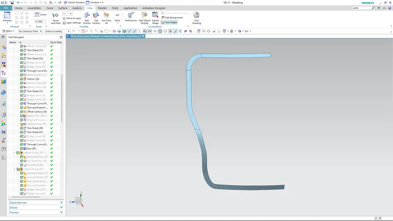
3. Connnecting Flange
A connecting Flange is created between the sealing flange and inner panel flange as shown in the figure.
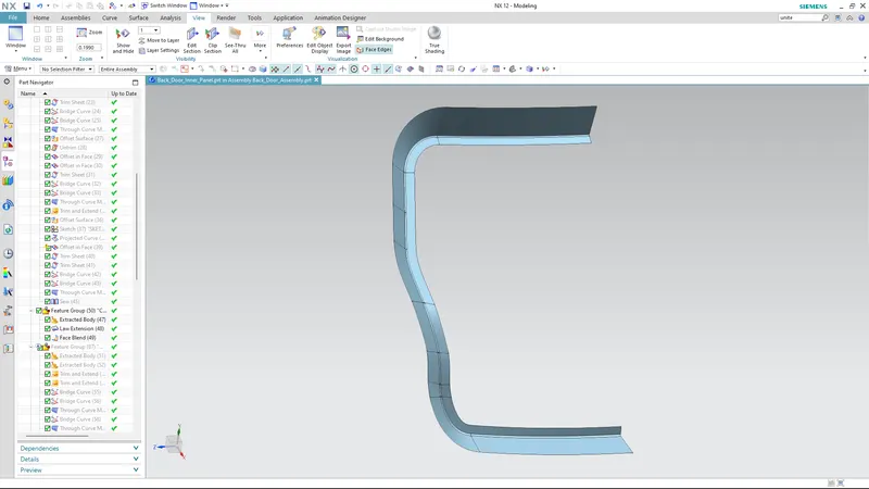
4. Windsheld Panel
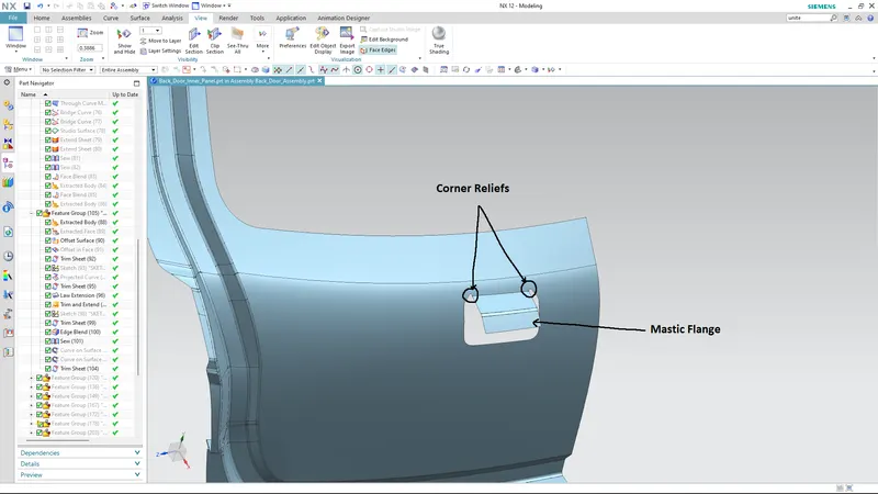
5. Mastic Flange
This mastic flange is created by punching the inner panel during manufacturing. One important consideration that should be accounted is the corner relief to prevent stress concentration at the corners.
Overall Representation of Flanges
6. Creating Embosses and Cutouts
7. Mounting Regions
Reinforcements:
These are the parts that provides additional strengths to the structure locally. Emboss alone is not enough to handle the weight of the gas stay, wiper motor, hindges, etc. therefore these reinforcements are provided to increase its strengths on that area.
Following are all the reinforcements provided to the car backdoor:
1. Hindge Reiforcement LH
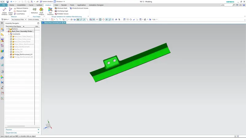
2. Hindge Reinforcement RH
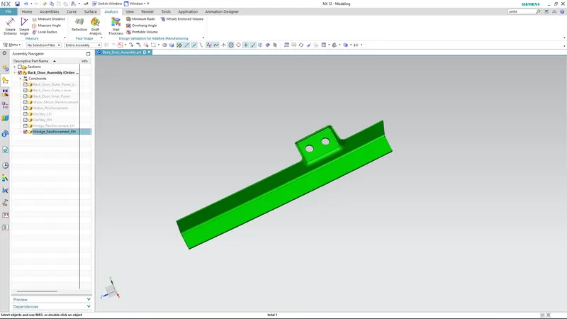
3. Gas-Stay Reinforcement LH
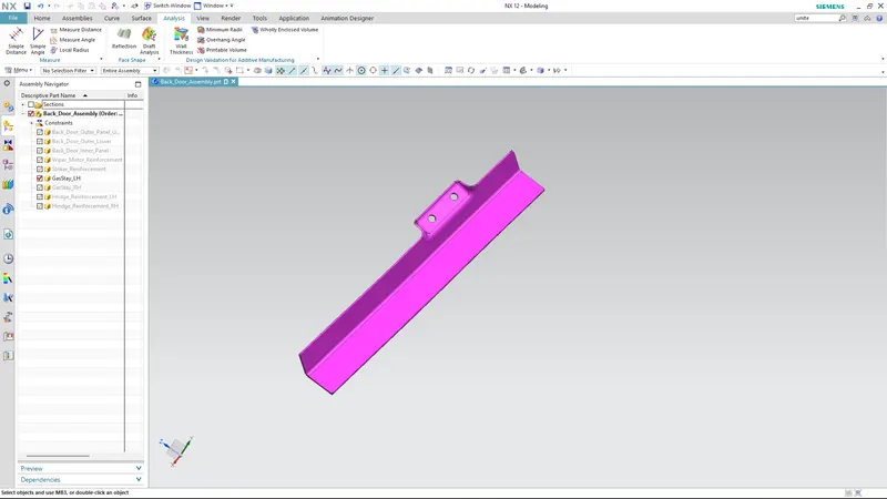
4. Gas-Stay reinforcement RH
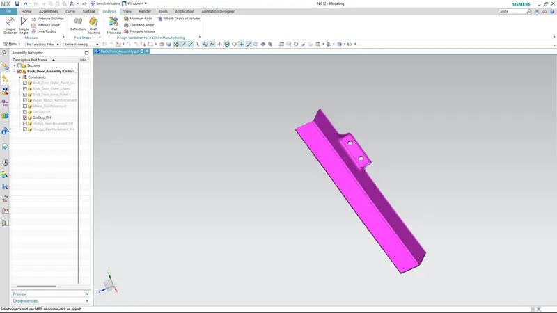
5. Wiper Motor Reinforcement
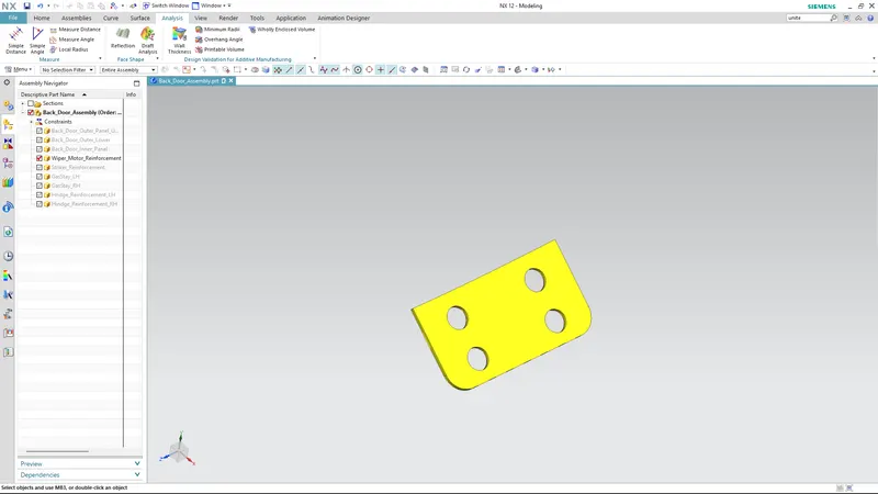
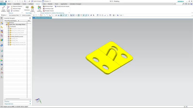
6. Latch and Striker Reinforcement
Positioning of Latch and Striker:
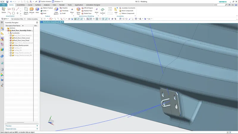
For the positioning the latch and striker, a trajectory passing through a midpoint of line/axis of the two hindges mounting regions is created. Also, a perpendicular line is drawn at the midface of the striker and this line should be tangent to the circle drawn as shown in the figure.
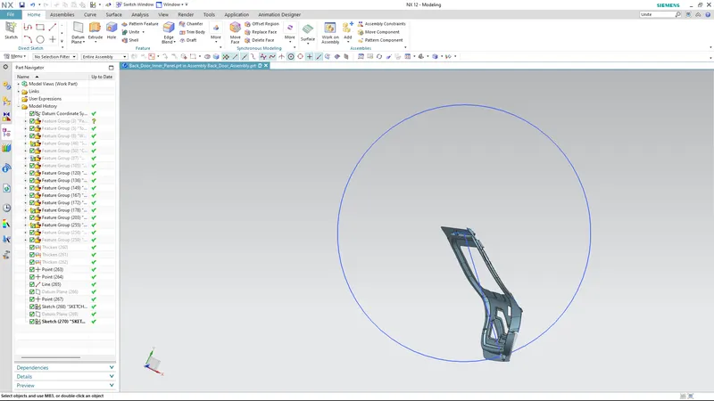
The Hindge axis is as shown below:
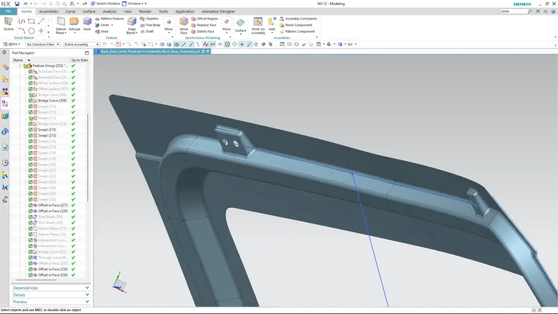
The below figure shows the trajectory followed by the striker which is tangent to the circle.
Hemming:
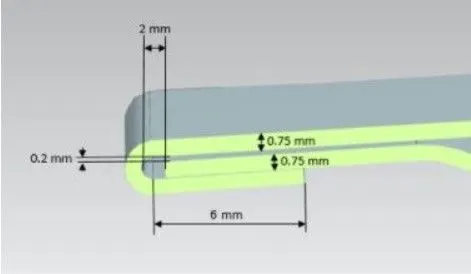
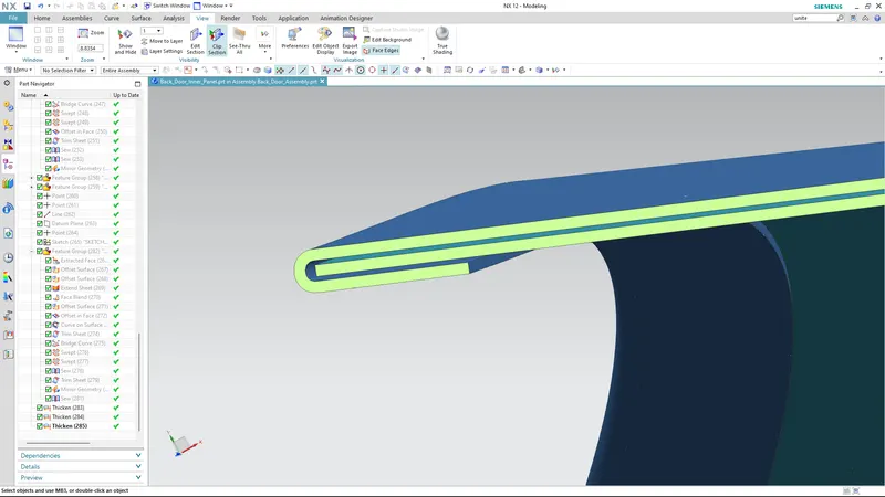
It is a process of attaching the outer panel of the backdoor to the inner panel of the backdoor by adding extra material on the outer panel and made to wrap around the inner hood panel. Some considerations should be taken while hemming such as the clearance distance. The hemming of the backdoor is as shown in the figure below:
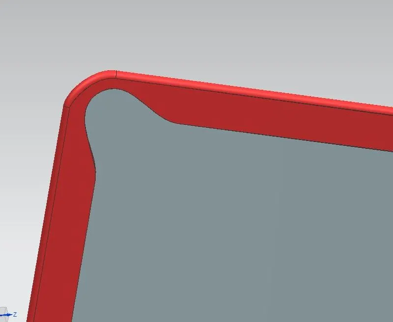
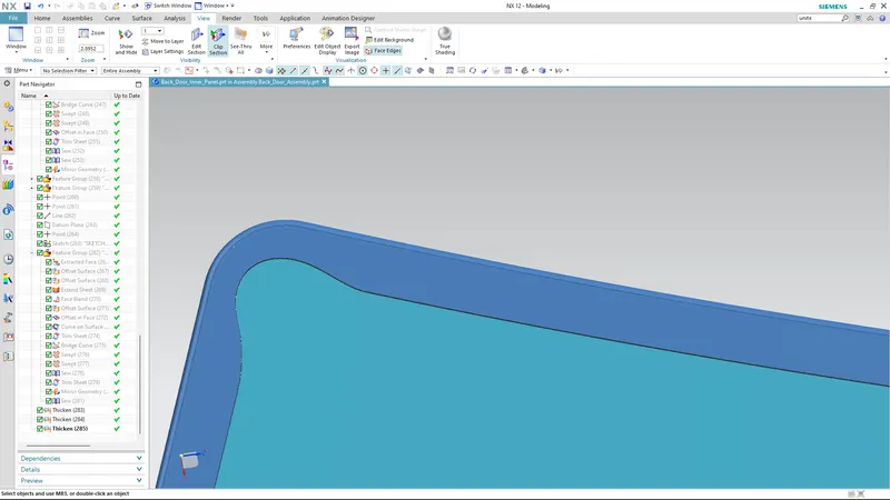
One more important to be considered while hemming is corner reliefs which is as shown:
Mastic Data:
Draft Analysis:
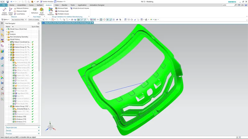
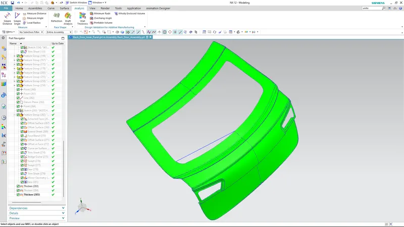
Draft Analysis is a method of checking the draft angle on various faces of a part in a particular direction. The draft angle should be positive for the feasibility of manufacturing the part. Generally, we take draft angle 7 or greater than 7. The draft analysis was conducted for the following sections considering tooling direction as the vector:
1. Backdoor Inner Panel
2. Backdoor Outer Surface
Draft Analysis using Catia
The draft analysis technique is used to analyze whether our part model created in CAD is manufacturable based on the draft condition applied. Here the part should get easily removed from the panel dies (in case of Sheet metal part) or Mold (in case of plastic).
No parts can be ejected from the tool if it is having a straight 90-degree profile from its base surface. A small draft angle is provided to each and every area of the component in order to get easy removal of the component from the tool.
Here we are providing a direction in which components should eject in order to get easy removal of components from the tool. In other words, it also lets us know whether the model is having a draft angle and how much is the draft angle from the tool direction.
The Types of Components for Draft Analysis
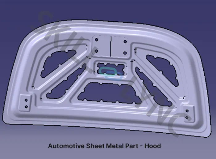
Draft analysis is performed on the components where the ejection of materials happens after the material is made inside the tools. In the case of Automotive Sheet Metal manufacturing, the blank sheet after turning into automotive panels like Hood, Fender, Roof, Side Doors, Back Doors etc. need to be removed from Panel Dies. If a considerable amount of draft angle is not provided, the removal of components from the tool will be difficult. It’s the same in the case of mold(plastic component) after getting filled inside the core and cavity, it needs to get ejected easily with the help of ejectors.
Procedure To Perform A Draft Analysis in Catia
Step 1
Change the view mode to Customize View Parameters and select the Material option from the Mesh.
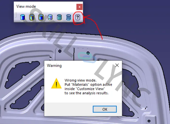
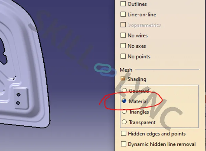
Step 2
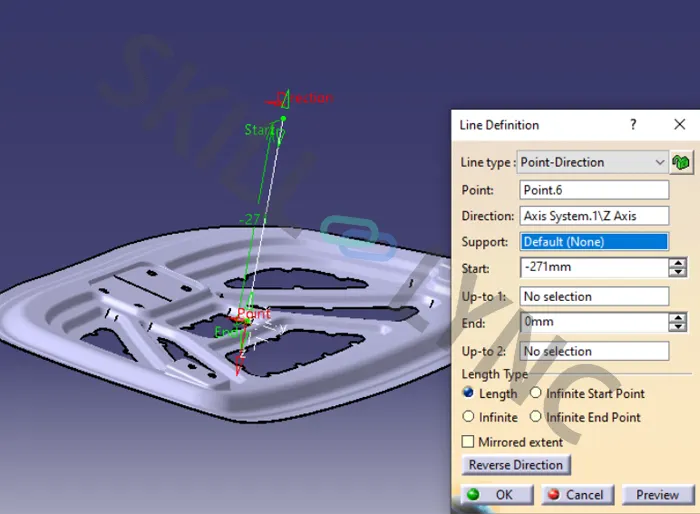
Next, you need to create a rough line, without considering a particular direction or parameters. The direction of the line may vary from component to component. To make the Draft Analysis easier, it will be better if the line is created from the CG point.
For that, we need to select the measure inertia option from the measuring toolbar.
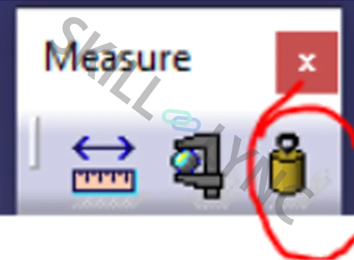
After that select the body from the tree for the Measure Inertia dialogue box.
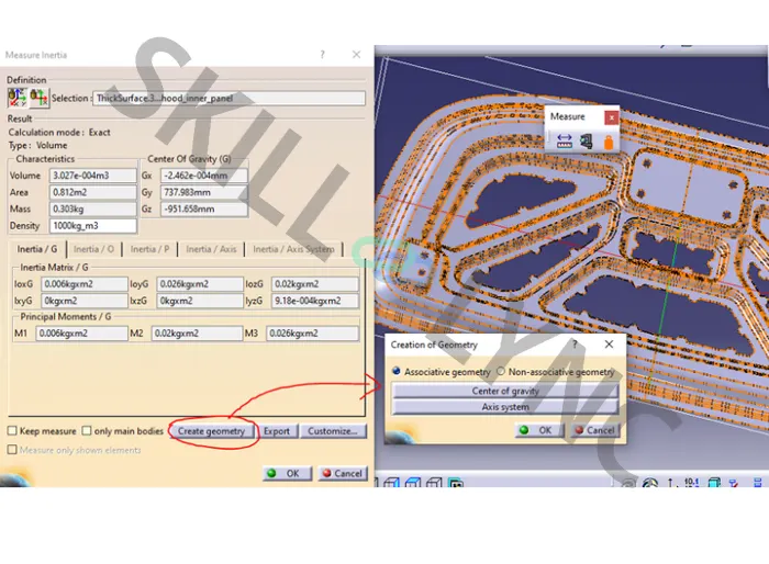
The CG point is represented inside a box on the intersection point of red, blue, and green. If we want to get to that point permanently, we need to select the created geometry and select both the center of gravity and the Axis system.
Step 3
Create a random line from the CG point using the point and direction option from the line command.
Step 4
Draft Analysis options are available inside the following workbenches:
- Part Design
- Generative Shape Design
- Wireframe and Surface for Building
- FreeStyle Shaper
Insert > Analysis > Draft Analysis
The draft Analysis dialog box with colour scale (with quick analysis mode) appears on the screen. So the first mode option is the quick analysis mode and the second is the full analysis mode. Here the quick analysis mode is used.
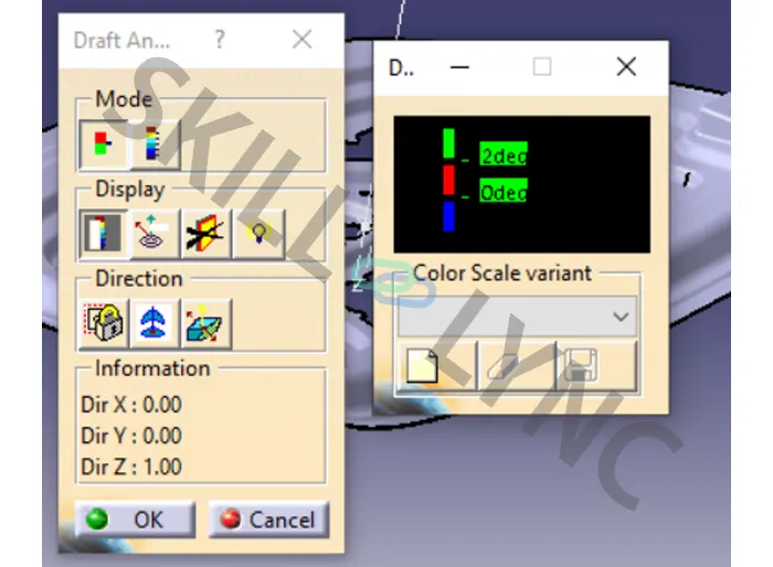
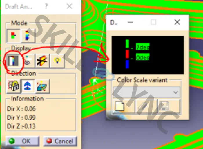
Change the value of green according to the draft angle provided to the part. Here for automotive sheet metal components, the ideal draft angle is 7 degrees.
Step 5
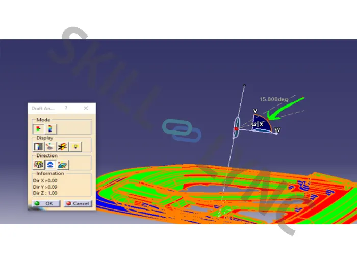
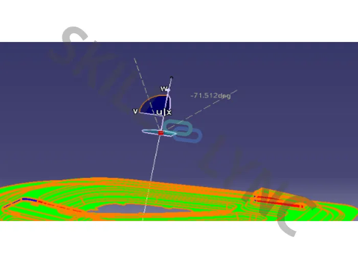
Drag the compass and place it over to the line.
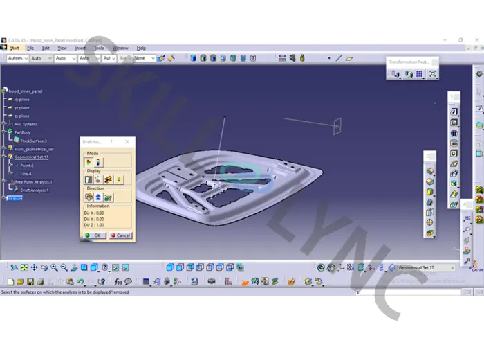
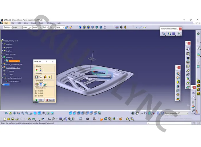
Select the compass icon from the direction of the Draft Analysis dialog box. The compass may get misplaced from its original position after clicking on the compass icon.
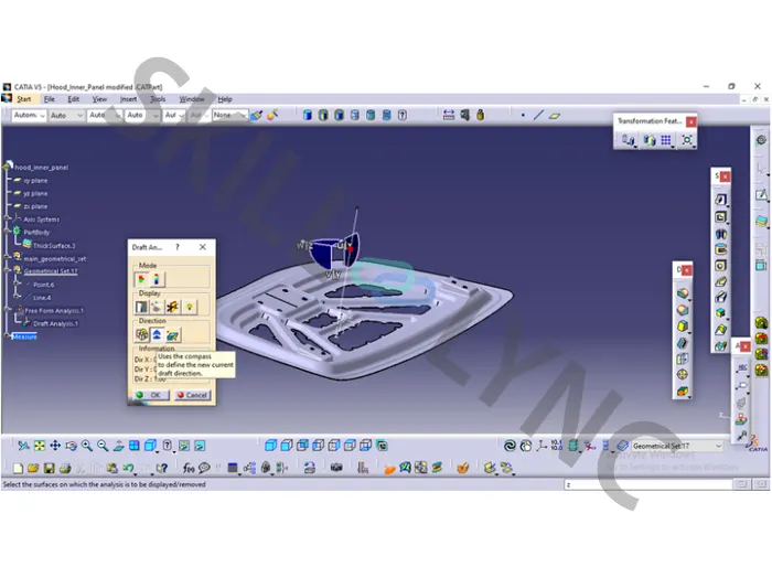
Select the compass again and place it over to the line properly one more time.
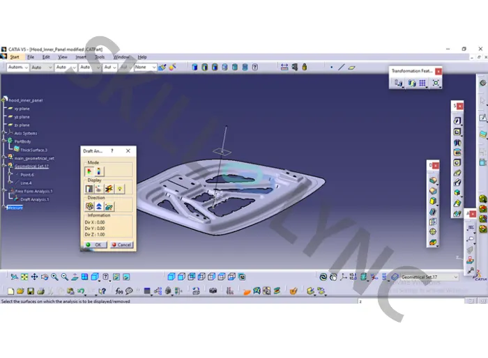
Step 6
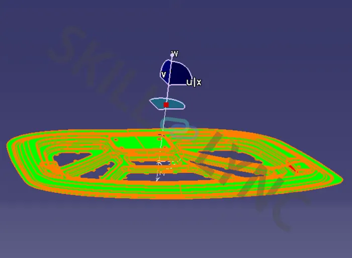
After placing it, click anywhere on the part.
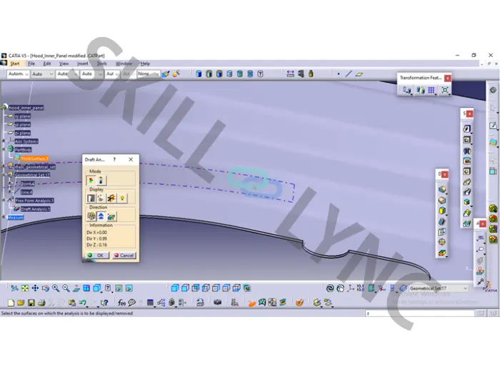
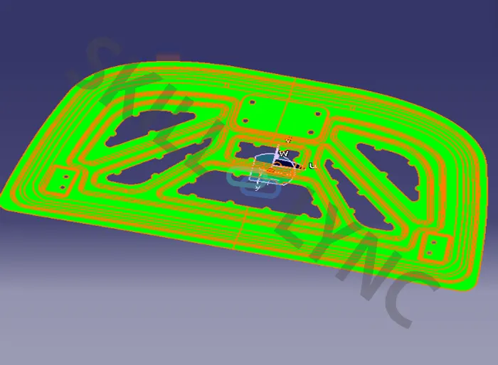
The appearance of the component will change afterwards.
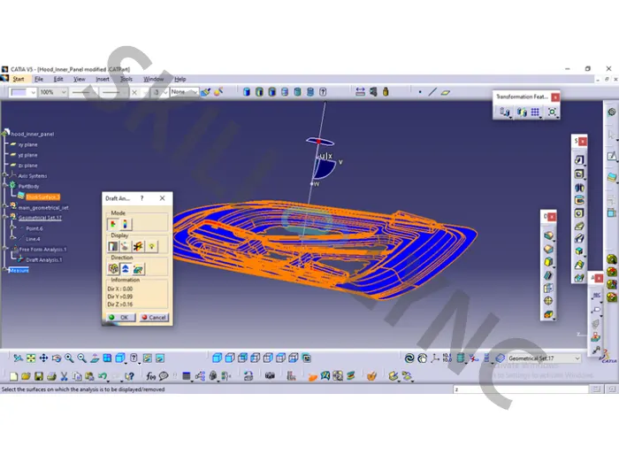
To get a clear picture, either we need to adjust the compass by holding the marked region of the compass and dragging it towards the opposite direction or by selecting the inverses draft direction option inside the direction of Draft Analysis
Step 7
After getting the green colour on the component, try to adjust the compass using the knob, and adjust the direction of the compass to get green on the entire top panel region.
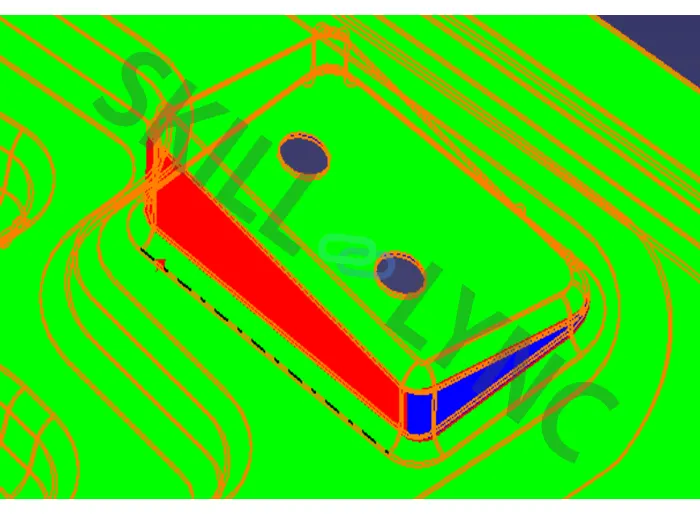
Try zooming in and checking if each and every region of the panel is showing green, if in some regions, red or blue is showing instead of green, those negative regions are below 7 degrees and have no draft applied on those regions.
Those blue and red negative regions need to be changed.
Step 8
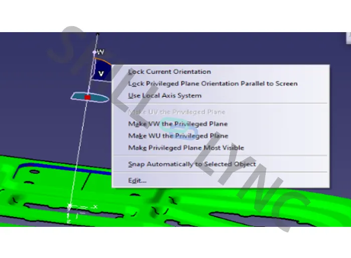
If we are ok with the result, right-click on the compass and lock its current position using lock current orientation.
Step 9
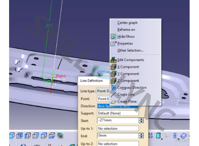
Click ok to the draft analysis dialog box to close it. Double click on the line and right click on the direction option and change the line direction to compass direction. The line will get oriented along with the previously locked compass draft direction.
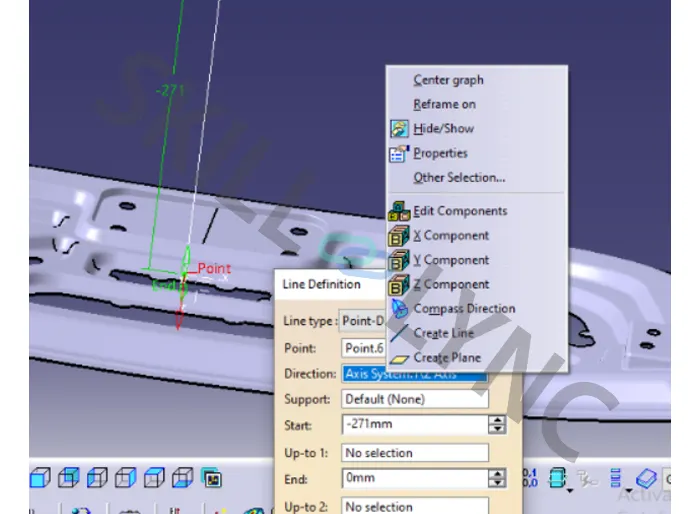
After the use, right-click again on the compass and unlock it. Also, reset the compass using the shortcut Alt + v + r. The compass will get reset to its original position. Later we can provide thickness to the line and change the appearance colour to green by right-clicking and selecting properties (which is an ideal colour used to represent draft direction).
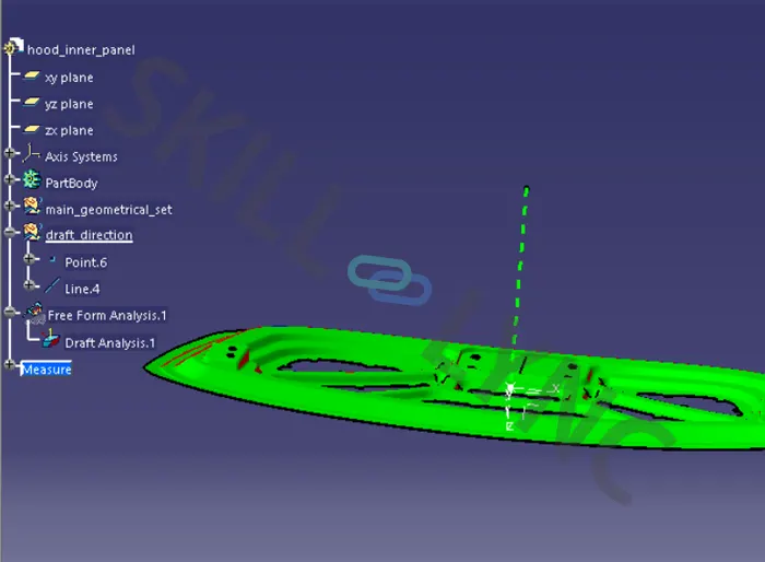
Exploring More Display Options
Show or Hide the Colour Scale
The first option inside the display is to show or hide the colour scale. This option is used to change the draft angle value according to the type of component used.
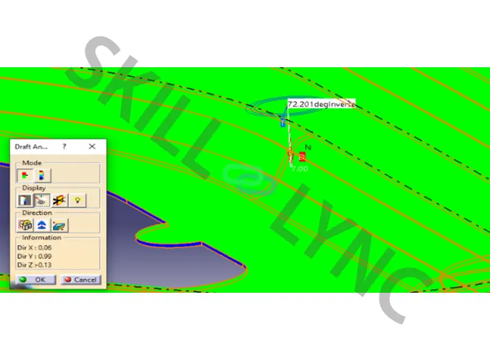
Analysis under the Running Point
This option is used to highlight the exact draft angle of that face. For that, we need to move the point along the faces.
No Highlight Representation / Light Effect
No Highlight Representation and Light Effect options are used to change the view type to get a clear highlight of the Draft Analysis result.
Draft Analysis of Plastic Components
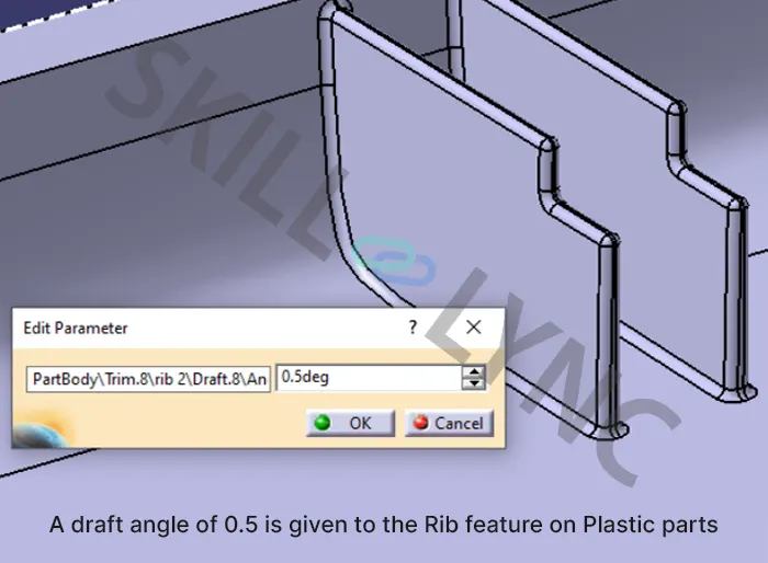
The ideal draft angle for the plastic components is 3 degrees. This may vary according to the functional requirement. Apart from the draft angle consideration, the remaining procedures for the draft analysis are similar to the above-mentioned steps. The draft angle provided for the plastic features is 0.5 degrees. This may also get varied accordingly.
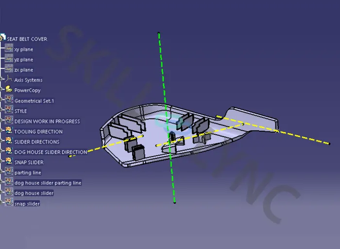
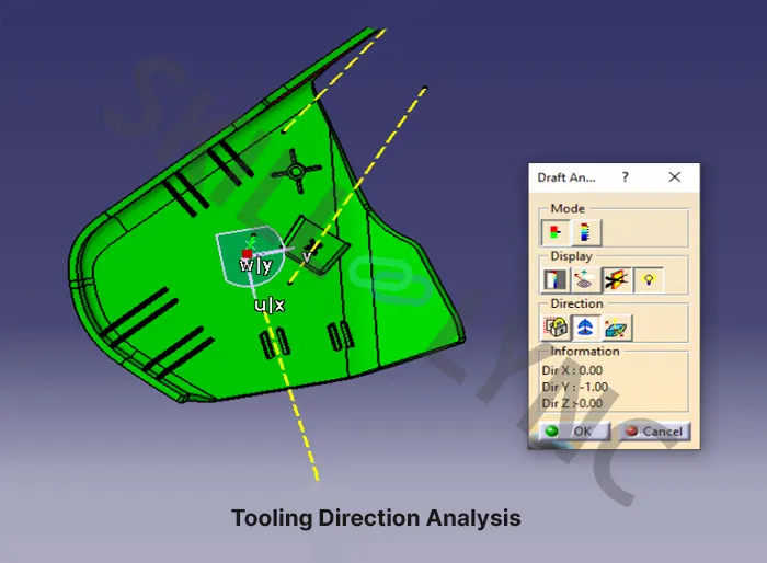
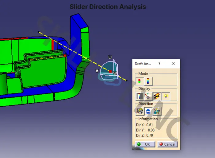
The above figure shows the tooling direction, slider direction, dog house slider direction, and snap slider direction of the plastic component. This is determined with the help of draft analysis with a draft angle of 0.5 degrees.
Conclusion:
Hence, the backdoor is designed with all the necessary reinforcements and embosses along with considering all the important design criteria.