Design of American chopper in Solidworks
Objective: - Design and Render the individual components of an American chopper and assemble them together to form a good, rendered design.
Introduction: - Orange County Choppers bikes are motorcycles featured on the television series American Chopper built by Orange County Choppers (OCC) for a specific corporate or celebrity customer. Theme bikes are motorcycles in which the theme of the motorcycle takes priority over everything else, influencing the frame dimensions, paint scheme, and overall 'feel' of the motorcycle.
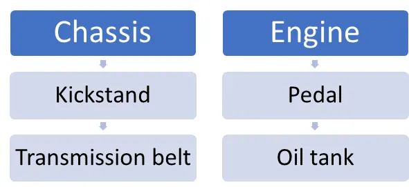
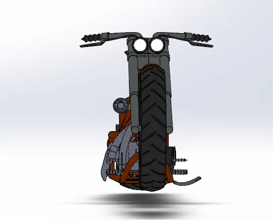
The American chopper is modelled and assembled in Solidworks. Individual components are designed using part. Assembled in assembly part of Solidworks. Assembly is created by following parts: -
- Chassis
- Engine
- Pedal
- Kickstand
- Transmission belt
- Oil tank
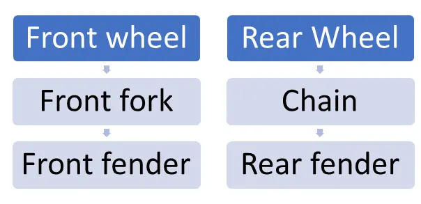
- Rear-wheel
- Front-wheel
- Chain
- Front fork
- Front fender
- Rear fender
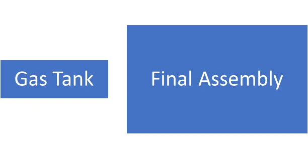
Design Methodology: This is the flow chart of design: -
- Boss/base extrude: - It is one of the surface tools to foam the surface bodies which are thin in nature. we can extrude the boundary edges of a face of a solid body or edges of a surface body in a customized direction.
- Extrude cut: It is one of the solid works design tools which helps to design to cut/remove material by projecting a sketched section normal to the sketching plane. You can use open or closed sections to create a cut. Removing material using a closed section creates a slot.
- Projected Curve: - It is one of the most used tools in drafting the design. It helps to get a single curve from two different curves drawn on different planes or the same plane. Create a Curve as the intersection of two projected sketches. Note that the projections from one sketch must intersect the other in one continuous curve for this operation to succeed.
- Surface loft: - It is one of the surface tools in solid works to draft the surface. It generates the surface from different 3D curves on different planes. Loft Surfaces are surfaces generated by multiple 3D Curves or existing edges creating a smooth tangency between the selected curves. It is done using a minimum of two profiles and a minimum of one guiding curve. Match Points are created between each selection denoting the orientation and path of the loft surface.
- Revolve: - It is one of the Solidworks features Create a sketch that contains one or more profiles and a centreline, line, or edge to use as the axis around which the feature revolves.
- Mirror: - Mirroring is another way that SolidWorks can create a “copy” of an existing object. Additionally, you must choose a plane to mirror parts. In most cases, you will have to create your own plane to have the mirror done the way you need.
- Sweep: - Sweep is the one feature in Solidworks that helps sweep a closed profile along a closed or open path.
- Pattern: - Pattern repeats the selected features in an array based on a seed feature. You can create a linear pattern, a circular pattern, a curve driven pattern, a fill pattern, or use sketch points or table coordinates to create the pattern.
- Dome: - A dome is a curved formation or structure. It is shaped like half of a sphere.
- Fillet: - Fillet/Round creates a rounded internal or external face on the part.
- Chamfer: -The chamfer tool creates a bevelled feature on selected edges, faces, or a vertex.
Part Modelling
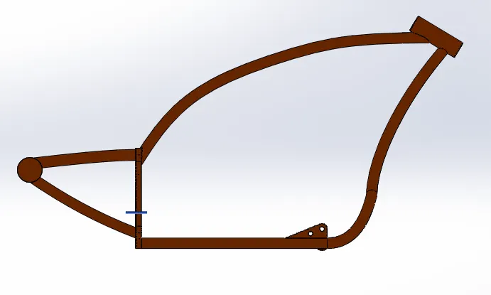
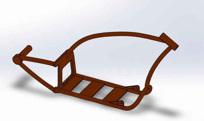
- Chassis- It is the main part of the vehicle which acts as a base. It is a frame of the vehicle. This part acts as a fixed part, and all other individual components were assembled in the chassis. It is a hollow tube structure in which the following tools are widely used. Swept is one of the widely used tools to extrude the surface on sketches on different planes.
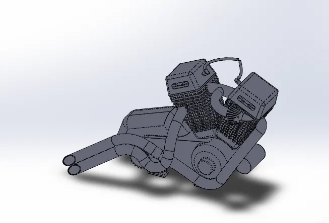
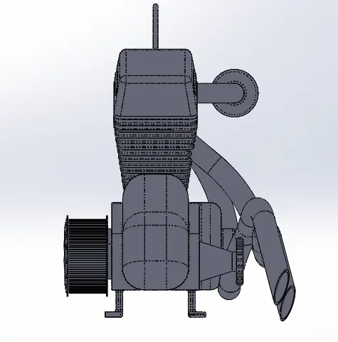
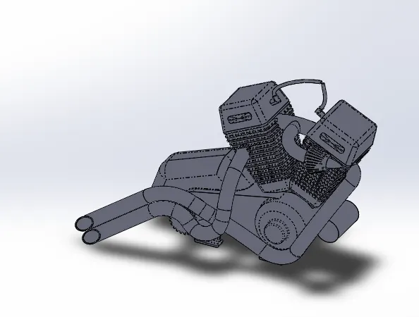
- Engine: - The engine is the heart of the vehicle. It is one of the designs of the most complicated parts. Using Sketch pictures for reference different projected curves are drawn to match the form of the engine fuel lines and swept in that direction. General solid features such as extrude cut, extrude, fillet and split are frequently used to draft the design.
- Wheel: - It is one of the major parts of the vehicles. It is attached to the back and the front sides of the chassis. Revolve is one of the important sketch features used to make the circular design. Cut extrude is also used to give patterns on the tire and disk plate. Its front-wheel consists of the following subparts: -
- Rim
- Tyre
- Hub
- Disk
- Calliper
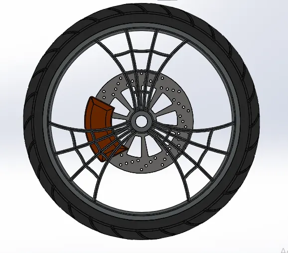
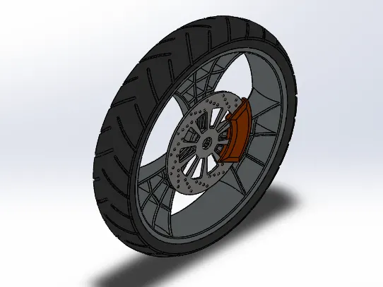
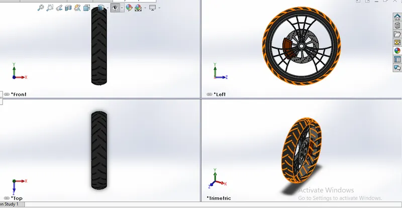
Rear Wheel consists of the following subparts: -
- Rim
- Tyre
- Hub
- Disk
- Calliper
- Sprocket
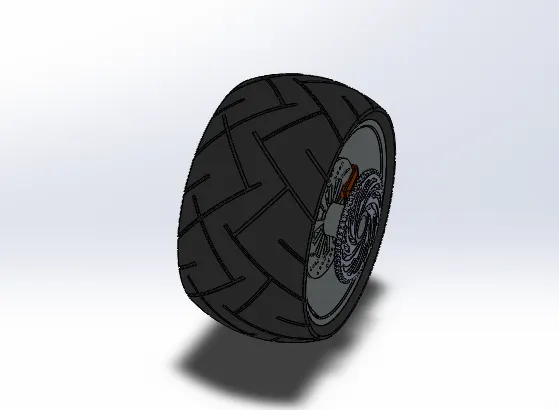
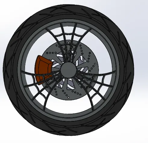
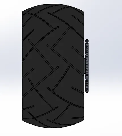
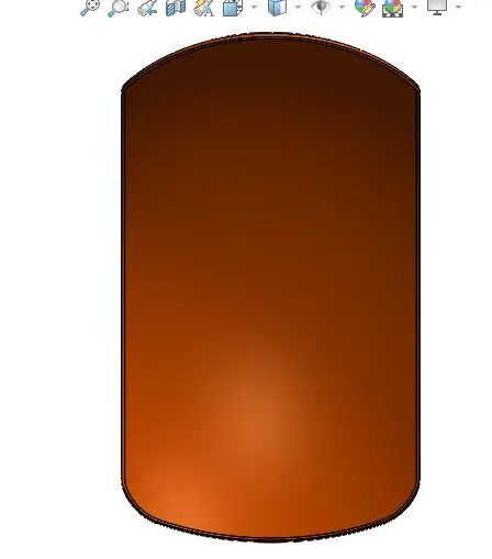
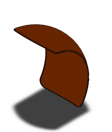
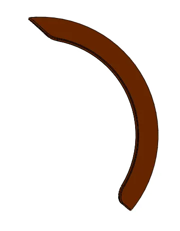
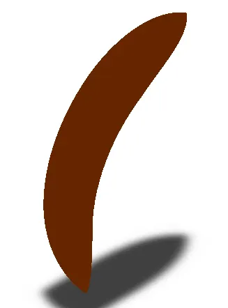
- Fenders: - A fender is an important part that protects the vehicles from mud and splashes. On both front and rear side wheels are covered with their fenders. To draft this part, Revolve option is used at a given particular angle (Not full rotation) as well as extra material split from the object.
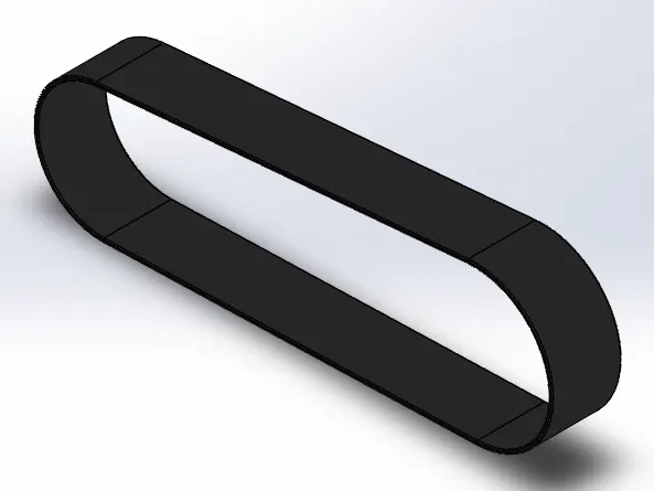
- Transmission belt: - It is one of the important parts used to connect/transfer the mechanical energy from one body to another. It is made up of flexible material. Bosses extrude and curve driven pattern tools used to draft the design.
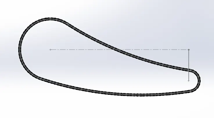
- Chain: - It is a power transmission object which transfers power very efficiently between the sockets. The boss extrudes and curve driven pattern is the important features used to draft the part.
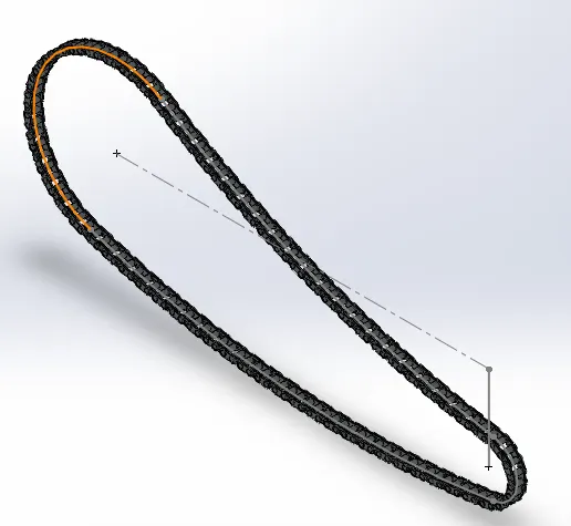
- Pedal: - It is the part used to give acceleration and brake on the vehicle. It is a foot lever structure. The boss extrudes, dome and liner pattern is the important features used to draft the part.
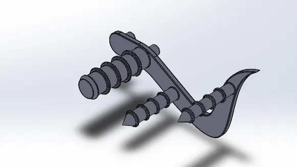
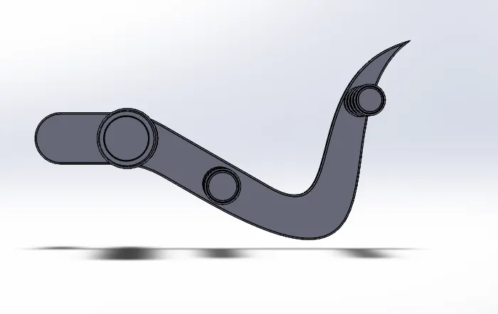
- Kickstand: - It is a foot leaver to kick start the vehicle. It is attached on the lower side of the vehicle. Loft and dome tool is used to draft the design.
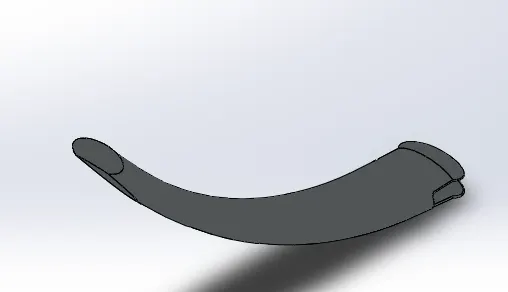
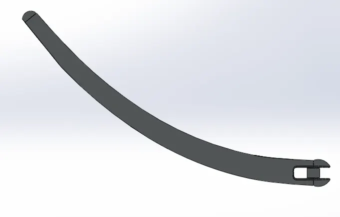
- Oil Tank- It acts as a reservoir of oil in the vehicle where oil is stored to give fuel in engine. Bosses extrude and shell option is used to create the object. The combine option is used to combine the two different bodies into one body.
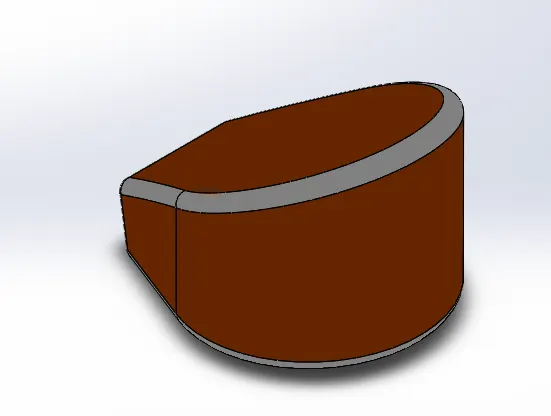
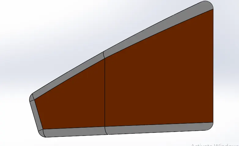
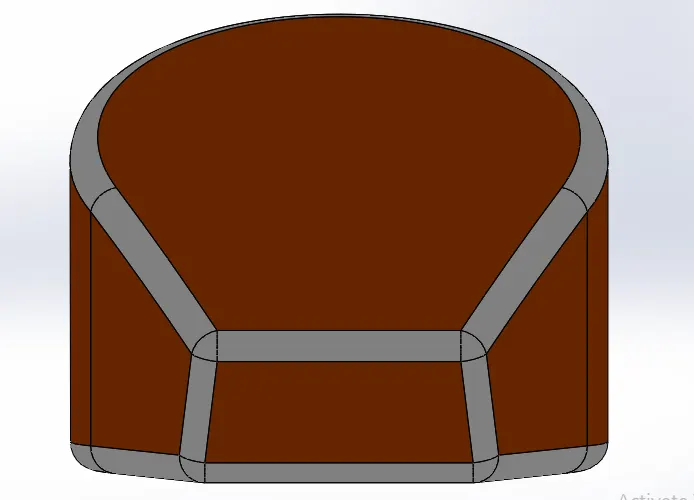
- Gas Tank- It is a gas reservoir. In this part, the seat is also attached with it. This is designed using a surface modelling approach. The surface loft is used to create the surface of the gas tank. Surface tools such as surface sweep and surface trim options are widely used to create the design.
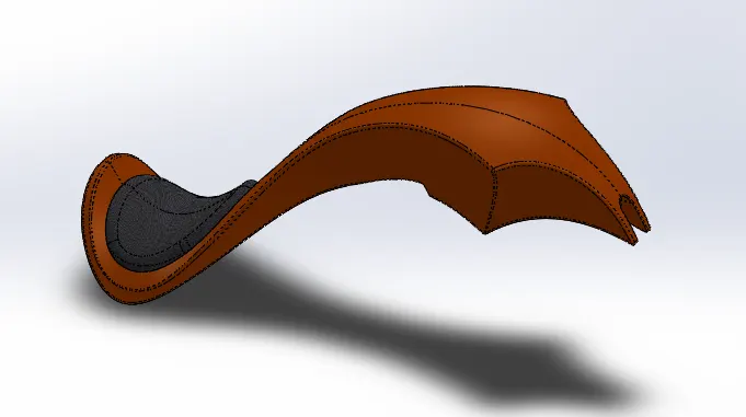
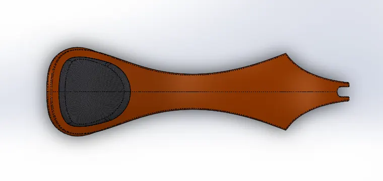
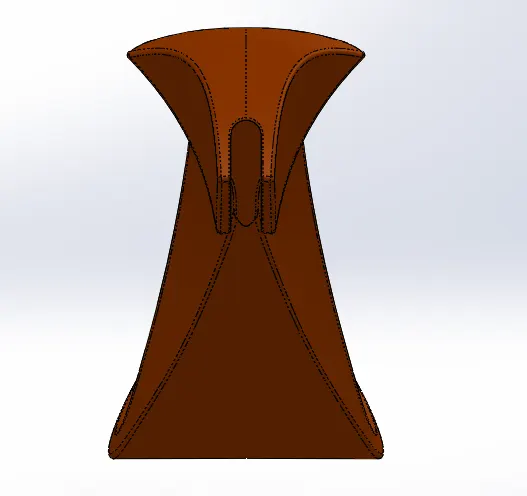
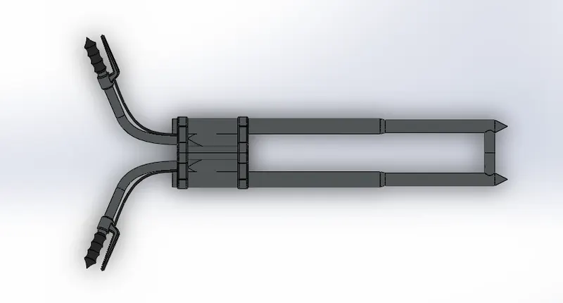
- Front fork: -The front fork prevents excessive weight on the front wheel during drastic sudden applications the break, softens bumping when driving on rough road surfaces. The front fork maintains proper damping through traction with the road surface. The design of the front fork is done using a simple sketch with some projected curve guided by sweep,boss extrude cut, revolve and circular pattern.
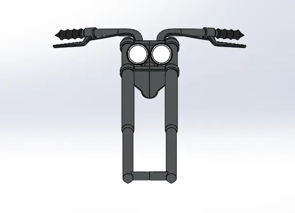
Assembly of the bike
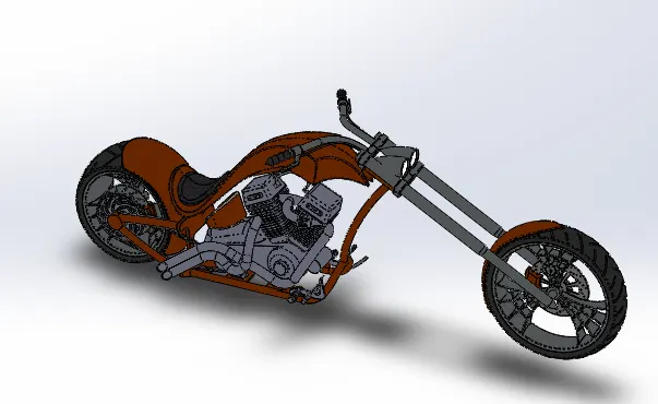
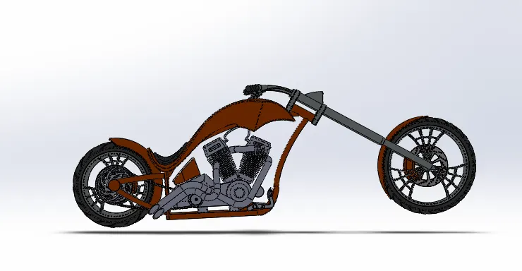
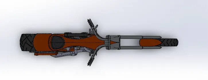
Assembly of individual components is done in assembly of Solidworks. The mating is done with respect to the chassis. Rendering can be done in Solidworks visualization or photview360.
Conclusion: -
The Solidworks design is completed.