DESIGN OF BUTTERFLY VALVE AND APPLYING GD&T TO IT
OBJECTIVES
The main objective of this project is to model a butterfly valve and apply GD&T to its individual parts and assemblies.
Introduction
The butterfly valve is a quarter turn rotary valve used to stop, regulate and start flow. The butterfly valve is easy and quick to open. A 90° rotation of the handle ensures that the valve is fully closed or fully open. Large butterfly valves are often equipped with so-called gearboxes, where the handwheel is connected to the valve stem via a gear.
This makes the valve easier to operate, but at the expense of speed
GD&T
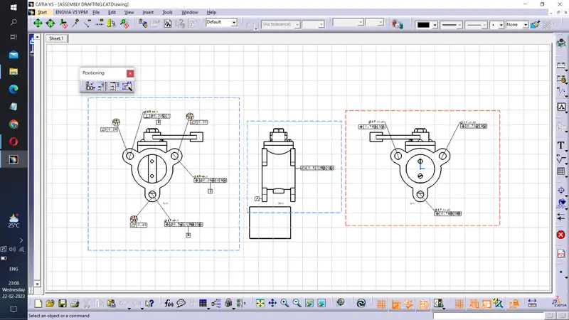
Geometric Dimensioning and Tolerancing (GD&T) is a system of symbols and rules that are used to specify the dimensions and tolerances of parts and assemblies in engineering drawings. Applied GD&T refers to the practical application of GD&T in engineering design and manufacturing to ensure that the parts and assemblies meet the required functional and quality specifications. The purpose of GD&T is to provide a clear and concise way of communicating the design intent of the part or assembly to the manufacturing team, while also allowing for a degree of variation in the manufacturing process
BUTTERFLY VALVE
The throttle opens or closes fully when the disc rotates half a turn. The throttle is a metal disc mounted on a rod. When the valve is fully open, the disc rotates half a turn, allowing fluid to flow freely. Rotate the disc an additional half-turn to stop fluid flow. There are several types of butterfly valves.
Each throttle valve has a different pressure and purpose. Once the various throttle body components are modeled, geometrical-tunic dimensions and tolerances are applied to each component and final assembly.
Butterfly valves belong to a family of valves called quarter-turn valves. During operation, a quarter turn of the disc will cause the valve to fully open or close. A "butterfly" is a metal disk mounted on a shaft. When the valve closes, the disc rotates to completely block the passage. When the valve is fully open, the disc rotates a quarter of a turn, leaving little to no obstruction of fluid flow.
Valves can also be opened progressively to regulate flow. There are many types of butterfly valves, each tailored to different pressures and applications.
Assembly
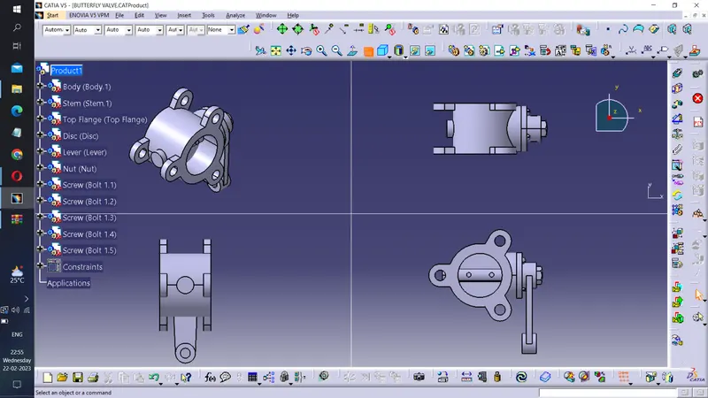
After modeling the various components of the valve, all parts were assembled using the assembly bench in Catia v5 software.
Final Drafting Image of the ASSEMBLY
Butterfly Valve - Components
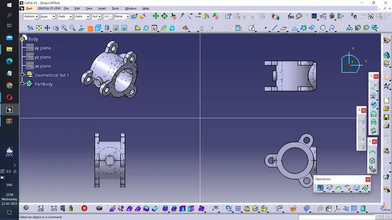
1. Body
Butterfly valves are secured between two pipelines using flanged couplings. Below is a butterfly valve body Designed using geometrical dimensions.
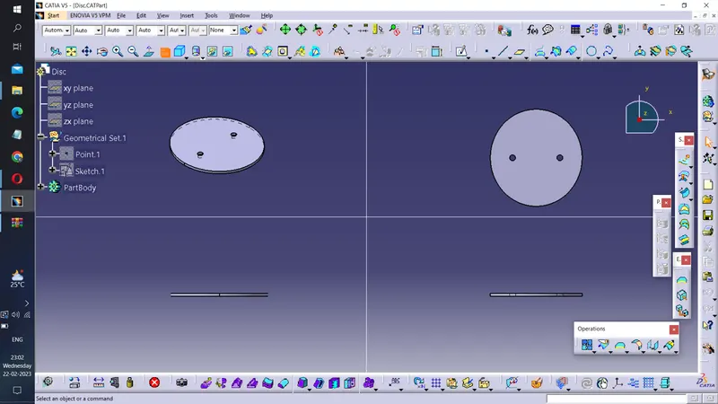
2. Disc
To fully open or close the disc, turn it half a turn (1/4 turn). The disc is mounted on the shaft. When the valve opens, the disc rotates and allows fluid to pass through. When you want to close it, the disc rotates to close completely. Because the flow of fluid stops.
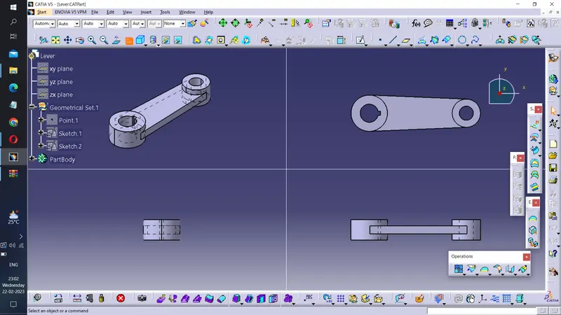
3. Lever
The lever is mounted on a shaft at the top of the shaft end outside the housing. A lever is used to control the rotation of the disc.
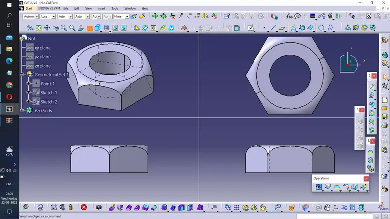
4. Nut
Attached to the top end of the shaft to hold the lever and top flange.
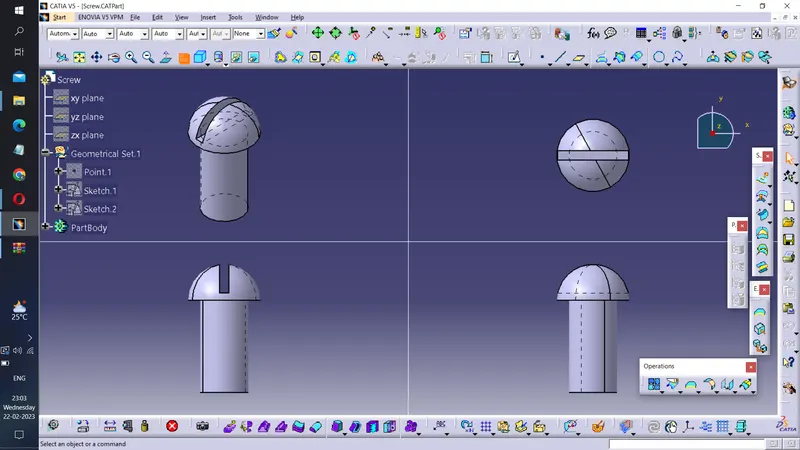
5. Screw
Screws are used to assemble the top flange and connect it to the body and shaft.
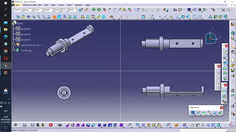
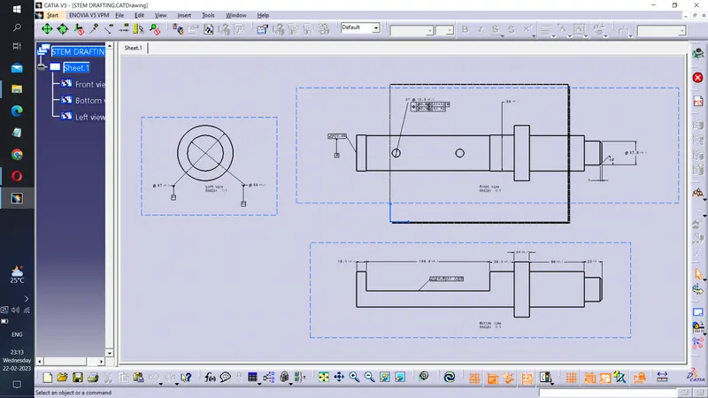
6. Stem
A disc, lever and nut are attached to this shaft.
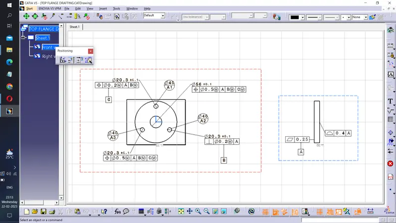
7. Top Flange
This is a kind of washer that attaches to the throttle body.
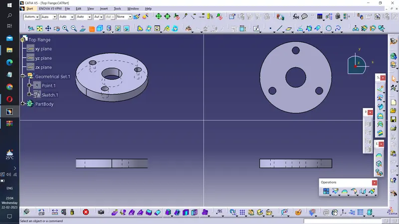
DRAFTING IMAGES FOR ABOVE MODELS
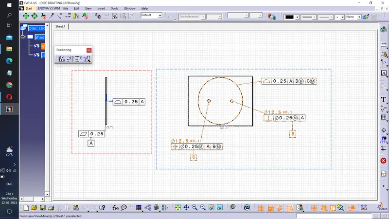
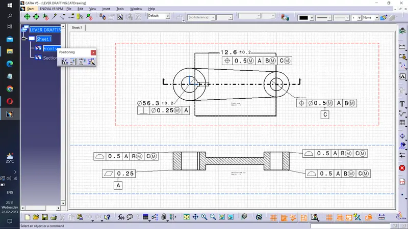
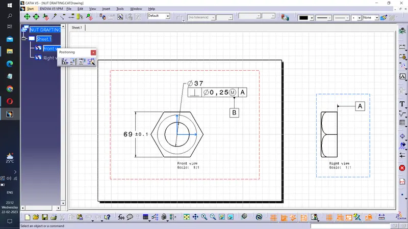
CONCLUSION
Butterfly valve was successfully designed and GD&T applied to all parts and the assembly of the Butterfly valve using CATIA V5 software.