Cyclone Separator Challenge
CYCLONE SEPERATOR CHALLENGE
Aim:- To perform analysis on cyclone separator and calculate the separation efficiency and pressure drop.
INTRODUCTION
Cyclone separators or simply cyclones are separation devices (dry scrubbers) that use the principle of inertia to remove particulate matter from flue gases.Cyclone separators is one of many air pollution control devices known as precleaners since they generally remove larger pieces of particulate matter. This prevents finer filtration methods from having to deal with large, more abrasive particles later on. In addition, several cyclone separators can operate in parallel, and this system is known as a multicyclone.Cyclone separators are generally able to remove somewhere between 50-99% of all particulate matter in flue gas. How well the cyclone separators are actually able to remove this matter depends largely on particle size. If there is a large amount of lighter particulate matter, less of these par0ticles are able to be separated out. Because of this, cyclone separators work best on flue gases that contain large amounts of big particulate matter.
Empirical models used to calculate the cyclone separator efficiency
1. Iozia and Leith Model
Iozia and Leith logistic model is a modified version of Barth Model, which is developed based on force balance. The model assumes that a particle carried by the vortex endures 165 the influence of two forces: a centrifugal force, Z and a flow resistance, W. The collection efficiency ηi of particle diameter dp can be calculated from
`etai=1/(1+((dcp)/(dp))^beta`
2.Li and Wang Model
The Li and Wang model includes particle bounce or reentrainment and turbulent diffusion at the cyclone wall. A twodimensional analytical expression of particle distribution in the cyclone is obtained. Li and Wang model was developed based on the following assumptions:
• The radial particle velocity and the radial concentration profile are not constant for uncollected particles within the cyclone.
• Boundary conditions with the consideration of turbulent diffusion coefficient and particle bounce re-entrainment on the cyclone wall.
• The tangential velocity is related to the radius of cyclone by: `uR^n=constant`
3. Koch and Licht Model
Koch and Licht collection theory recognized the inherently turbulent nature of cyclones and the distribution of gas residence times within the cyclone. Koch and Licht described particle motion in the entry and collection regions with the additional following assumptions:
• The tangential velocity of a particle is equal to the tangential velocity of the gas flow,i.e.there is no slip in the tangential direction between the particle and the gas.
• The tangential velocity is related to the radius of cylone clone by: `uR^n=constant`
4. Lapple Model
Lapple model was developed based on force balance without considering the flow resistance. Lapple assumed that a particle entering the cyclone is evenly distributed across the inlet opening. The particle that travels from inlet half width to the wall in the cyclone is collected with 50% efficiency.
Procedure
1. Preparing the geometry
First the STEP file of a cyclone seperator was uploaded on spaceclaim.Then the Fluid volume was extracted by using "Extract Volume" function of spaceclaim. Then the walls of the cyclone separator was selected and was suppressed of physics
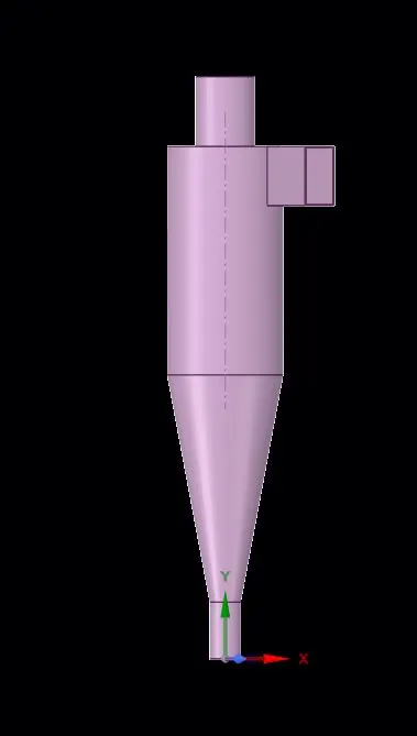
1.1 Image of Cyclone separator
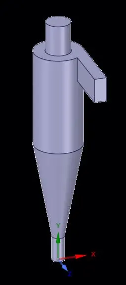
1.2 Image of Fluid volume
2. Meshing
Then the meshing was opened and a triangular mesh was generated of element size of 6mm. Also the inlet and the two outlet where also marked.
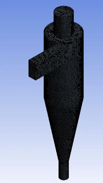

3. Setup
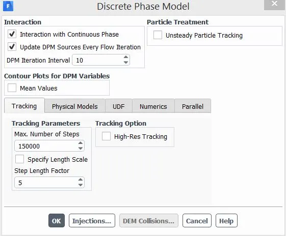
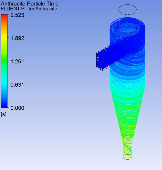
After meshing fluent was opened. The viscous model for the Simulation is RNS k-epsilon model with swril flow domination.After that the Discrete phase model was setted up.For the simulation coupled flow type is used.The other details are given in the snapplet below.After that an injection was created. The material injected is antharcite which are coming with the air from the inlet.The other detail are given below
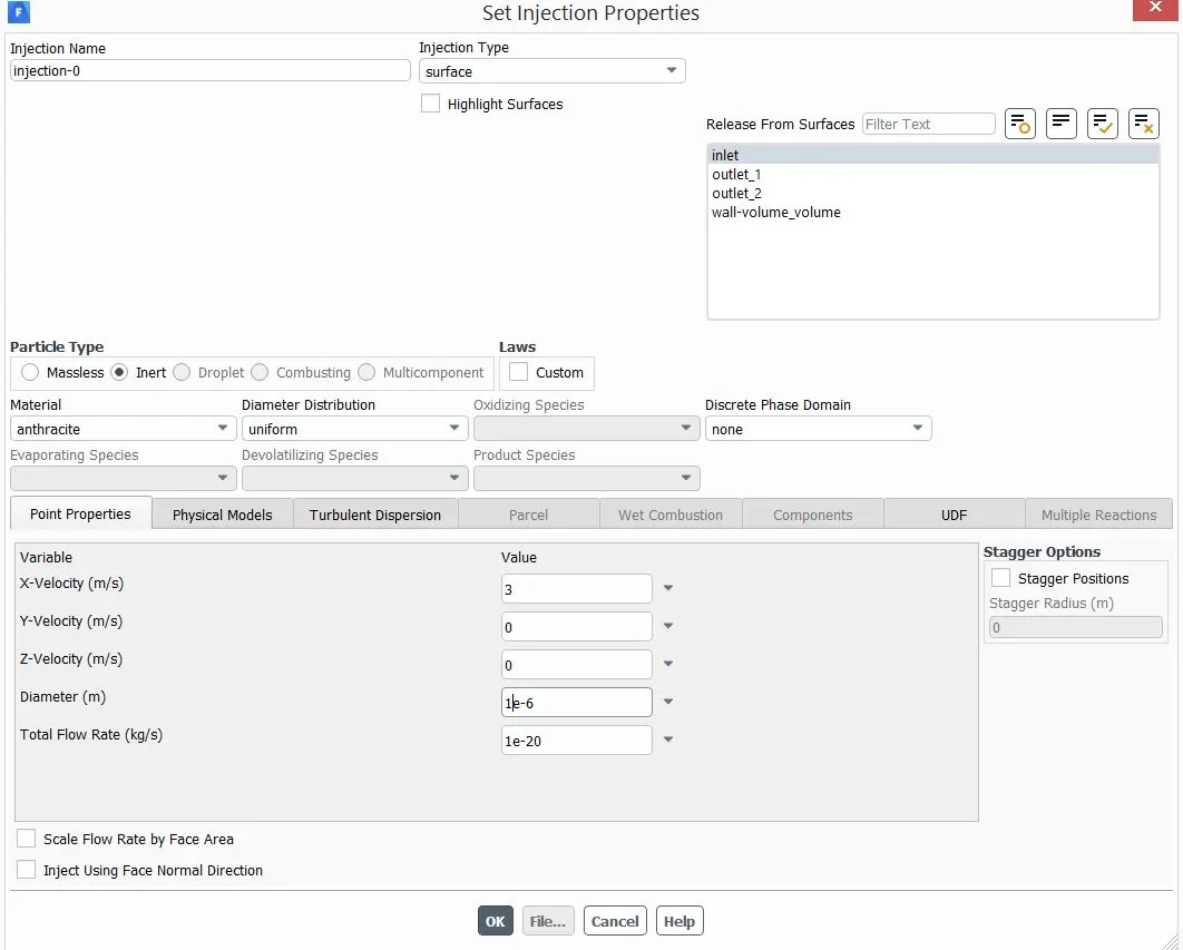
Then in boundary condition the the velocity of air was given which is varied according to the cases.The BPM setting for inlet and two outlet are as follows
1. Inlet- Reflect
2. Outlet(top)- Escape
3. Outlet(bottom)- Trap
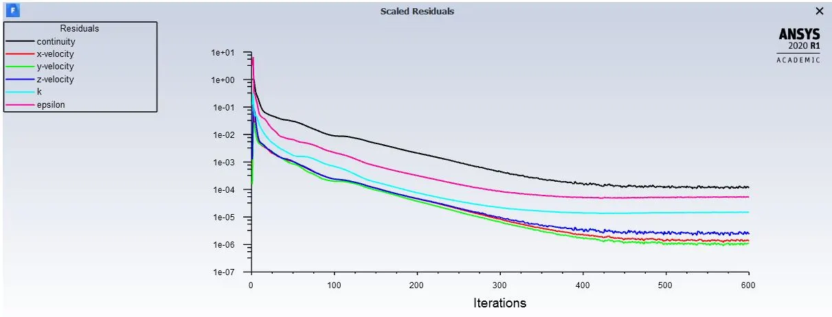
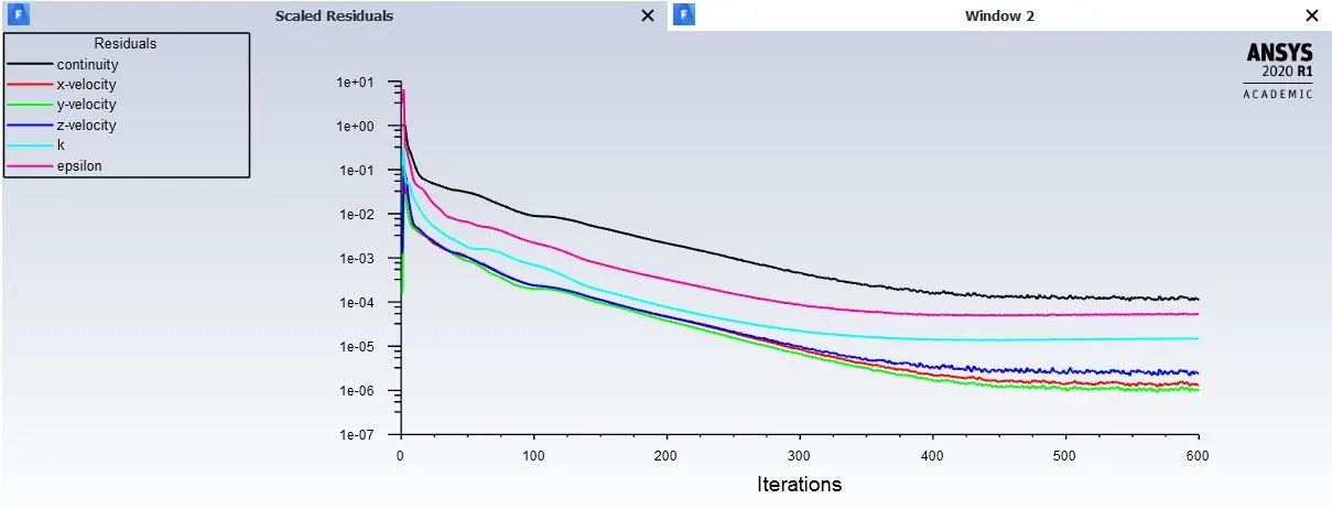
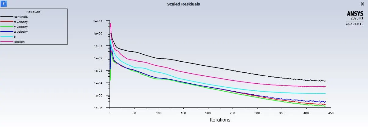
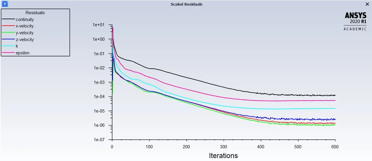
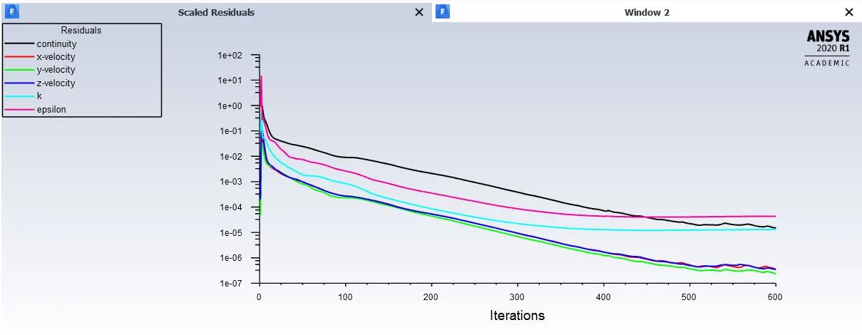
Then the Initailzation was done used standard Initailzation and the calulation was done for 600 iterations
4. Simulation
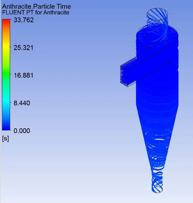
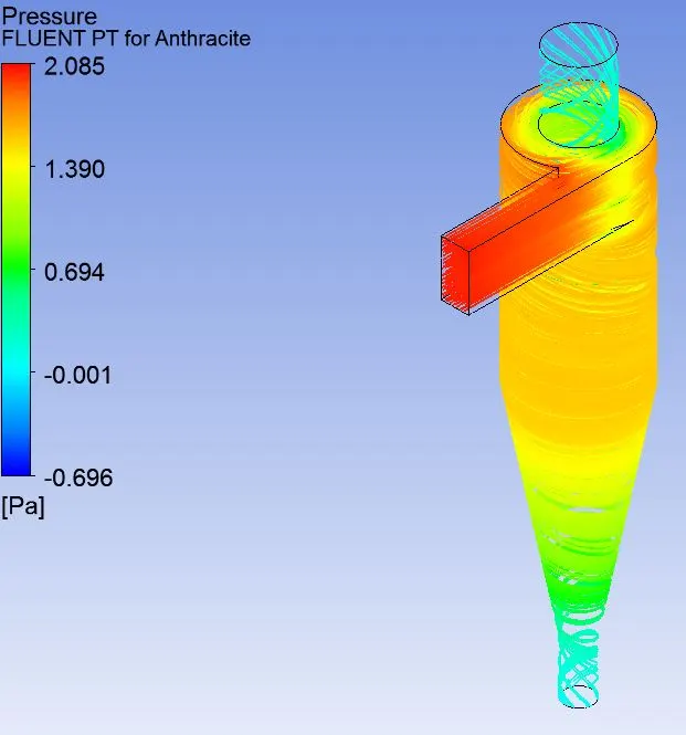
For the simulation there are two cases. In first case the velocity was kept constant at 3 m/s for both air and antharcite but the particle diameter was change from 1e-6m to 5e-6m. In second case the particle diameter was kept constant and the velocity of injection and air were varied from 1m/s to 5m/s.
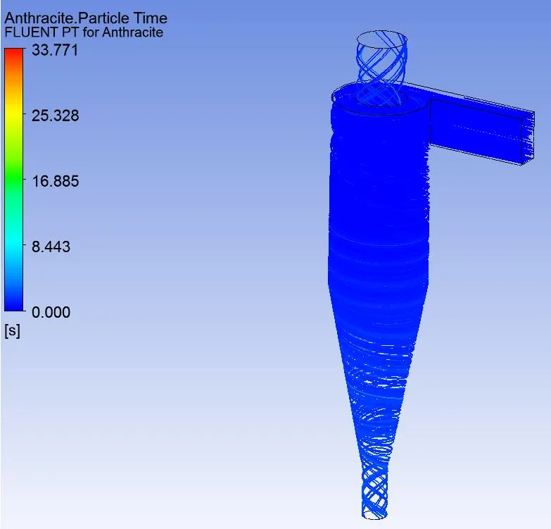
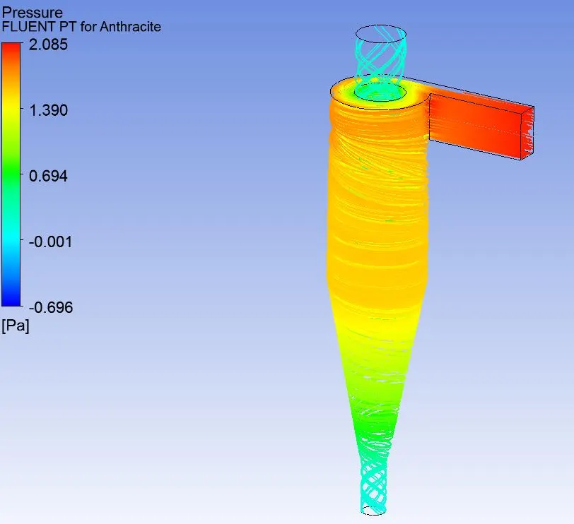
Case 1.1- Particle diameter: 1e-6 m

Case 1.2- Particle diameter: 3e-6 m

Case 1.3- Particle diameter: 5e-6 m

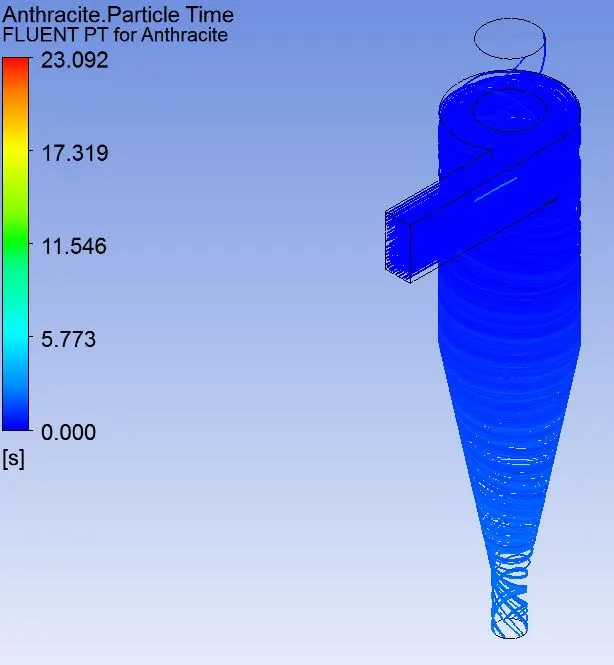
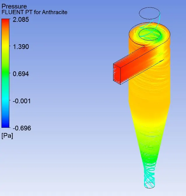
Case 2.1- Velocity of antharcite and air: 1m/s
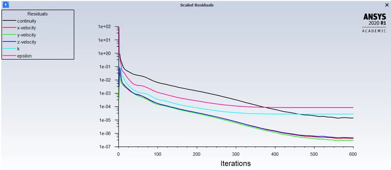

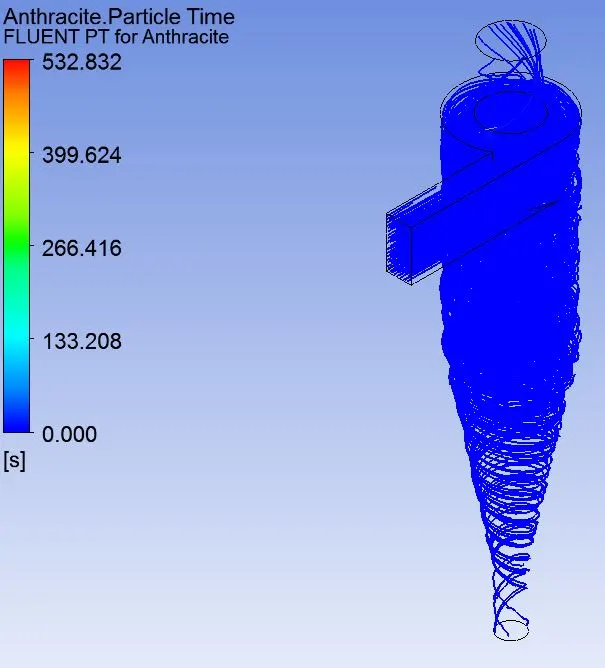
Case 2.2- Velocity of antharcite and air: 3m/s

Case 2.3- Velocity of antharcite and air: 5m/s

5. Result
From the first case it was found that as the particle diameter decreases the efficiency of the cyclone seperator also decreases keeping the velocity constant.The table below shows the result.
Efficiency(`eta`)=particle trapped/Total No of particle
| Case No. | Total No. of Particle | Particles Trapped | Particle diameter | Efficiency`(eta)` |
| 1.1 | 288 | 159 | 1e-6 | 55.20 |
| 1.2 | 288 | 189 | 3e-6 | 65.62 |
| 1.3 | 288 | 234 | 5e-6 | 81.25 |
From second Case it was observed that as the velocity increased the efficieny of cyclone seperator also increased keeping the particle diameter constant
| Case No. | Total No. of particle | Particles Trapped | Particle velocity(m/s) | Efficiency(`eta`) |
| 2.1 | 288 | 6 | 1 | 2.08 |
| 2.2 | 288 | 238 | 3 | 82.26 |
| 2.3 | 288 | 287 | 5 | 99.65 |