Creation of Multiple viewports, Scaling the drawing and setting in Template in AutoCad
QUE 1]
AIM-
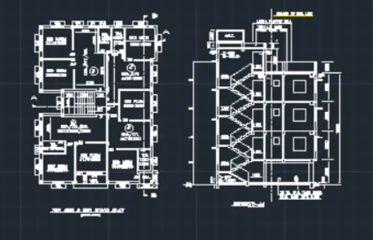
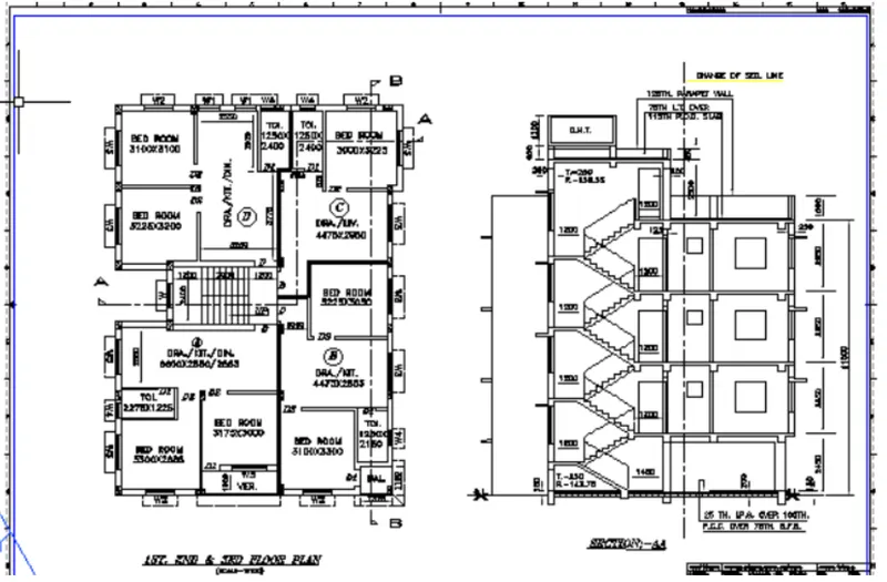
TO create the layout floor plan section AA as shown in the figure by using the AutoCAD tool
INTRODUCTION -
The floor plan given is an apartment building with sample plans 1st 2nd and 3rd floors
each floor consist of four houses three two-bedroom flats and one single bedroom flats one single bedroom flat with kitchen and living room
PROCEDURE
STEP 1 ]
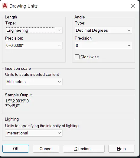
- In the command prompt type units .mm
- In the command prompt type climax.100.100
- In the command prompt type limits .0 .0
- In the command prompt type zoom .0
STEP 2 ]
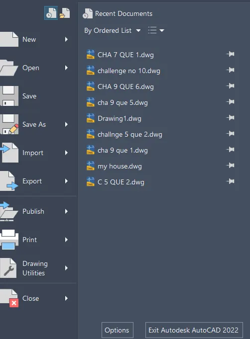
- command open file
STEP 3
- go to layout tab and delete the current viewports available
- right click on layout tab
- click on from template from pop up click on tutorial m-arch
- right click on layout and rename
command templet 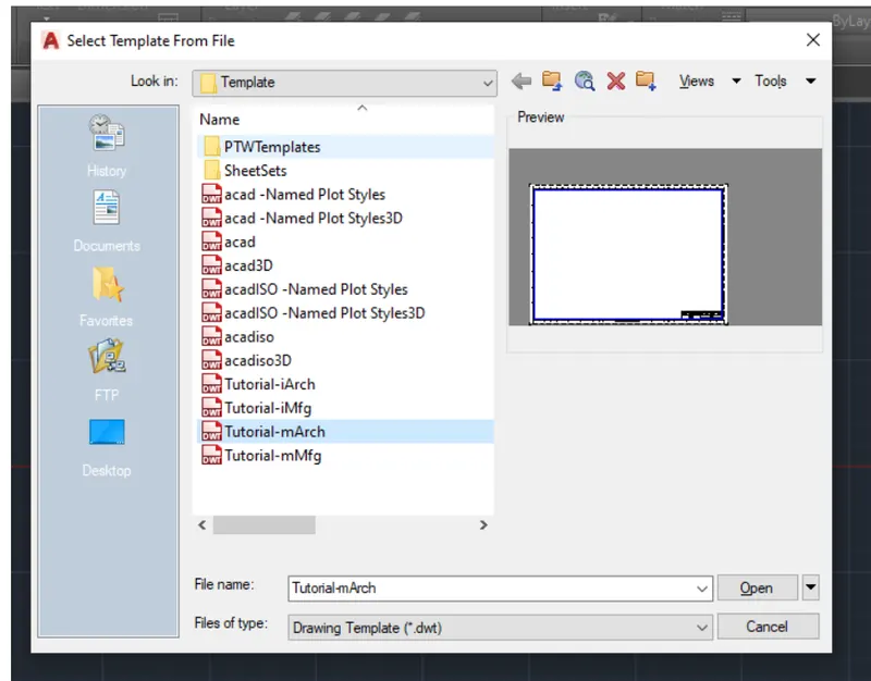
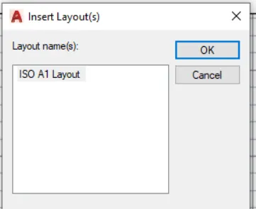
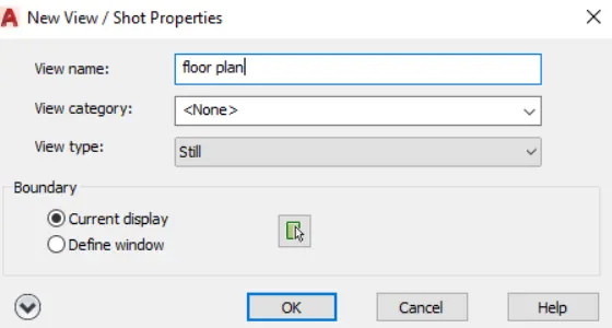
STEP 6
- creating viewports
- draw rectangular from top of layout dim 400*445
STEP 7
- go to module space
- select floor plan view created
- click on set current
- go to paper space
- select viewports as
- second rectangular drawn
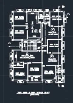
STEP 8
- go to paper space or ps
- select the two viewports created and go to properties change the display locked to yes
- adding details to the template- for changing the data of the attribute go to the batman or double to enter the value the values are changed as follows and dimension of viewports and text regarding scale as 1:50
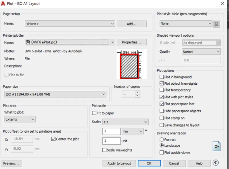
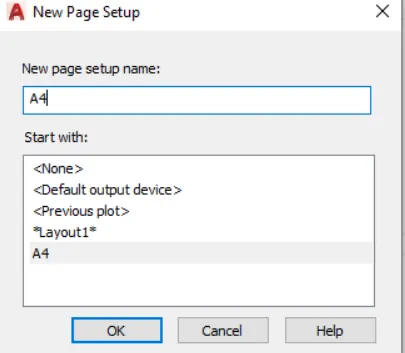
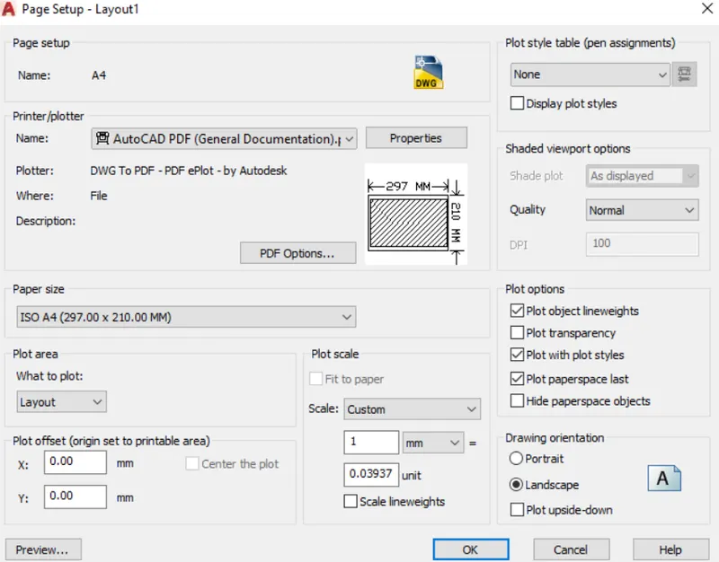
- plotting- type plot and click on enter or select plot from menu bar .set name as week_10_layout,change printer to autocad pdf.set paper size as iso A1,change plot area to layout,change plot style table to monochrome.ctb,now check the preview for adjustments,press ok to plot,select the path and set name
then print
RESULT-result of the given challenge consist of layout created from standard autocad layout
QUE 2
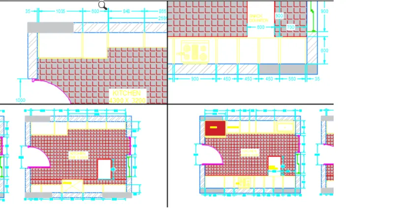
AIM-TO create the kitchen layout with four views parts as shown in figure
PROCEDURE-
- open Autocad
- change unit as per your requirement
- type UN IN command box and press on enter
- change units to decimal and prescisionto 0.00 and insertion scale to mm
- next type D in command box and press enter
- xref command helps attaching other drawings in the workspace,using this command the extension line can be drown
- all the references related to colour,text ,size,shape ,lineweight,lineshape can be captured and used in current drowing
- also it is used to make changes in xref plane,new layers of same name or different name using attachment or overlay option
- xclip command is used in creating clips of the xrefed(external referance)drowing
- type xref in command box and press enter
- click on attachment ,keep scale as 1 ,preess on ok and then specify point of insertion
- click on insertion point to specify pount of insertion
- in pop up click on insert the drawing into w10 q1 along with layers
- creating layout-go to layout tab and delte the current viewports available
- right click on layout tab click on from template,from pop up click on tutorial m-arch
- right click on layoutand press on rename and type
- creating views-go to model tab,typr v and press enter,click on new,type name as kichen 1,click on define windoe,select the kichen plan,press enter,click on ok,click on new,type name as kichen 2,click on define window,select the kichen plan,press enter,click on ok
- creating viewports-draw rectangular from top of layout dim 400*445,drow another rectangle adjacent to rectangle from top right corner with dim 375*445
- go to paper space or ps-type mv in command box and click on object in command box,select the objest as viewports to first rectangle drown
- go to model space-type v and press enter,slect the floor plan view created and click on set current and click okay,change scale to 1:50/2% and plan the figure to adjust
- go to ps-select the two viewports created and go to properties,change the display locked to yes
- chnaging layers-layers are changed for better visibilty .for viewports 1 and 2 respectively
adding details to tempalate-for changing data of attributr ,go to batman and double to enter the value ,the values are changed as follows and dimension of viewports and text regarding scale as 1:50
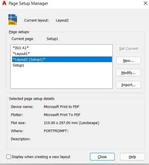
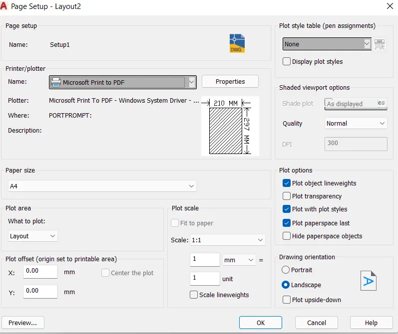
- plotting- type plot and click on enter or select plot from menu bar .set name as week_10_layout,change printer to autocad pdf.set paper size as iso A1,change plot area to layout,change plot style table to monochrome.ctb,now check the preview for adjustments,press ok to plot,select the path and set name
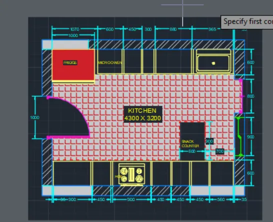
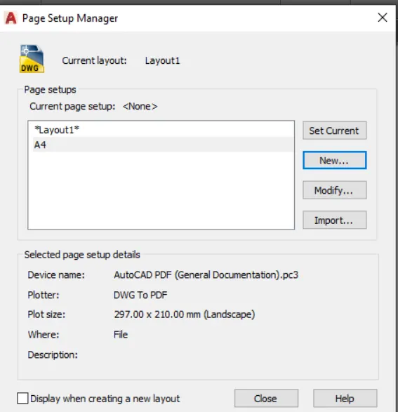
RESULT -
Q 3]
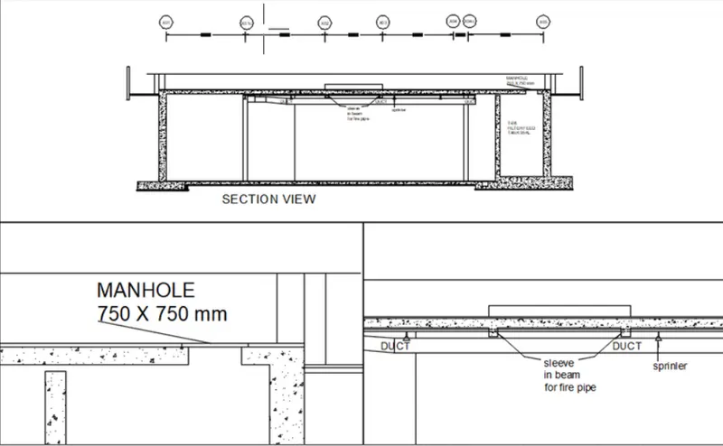
AIM-to create the three viewport layout of an industrial building as shown in figure
PROCEDURE-
- open Autocad
- change unit as per your requirement
- type UN IN command box and press on entering
- change units to decimal and precision to 0.00 and insertion scale to mm
- next type D in the command box and press enter
- xref command helps to attach other drawings in the workspace,using this command the extension line can be drown
- all the references related to colour,text ,size,shape ,lightweight, lineshape can be captured and used in current drowing
- also it is used to make changes in xref plane,new layers of same name or different name using attachment or overlay option
- xclip command is used in creating clips of the xrefed(external reference)drawing
- type xref in the command box and press enter
- click on the attachment,keep scale as 1, press on ok, and then specify the point of insertion
- click on insertion point to specify the point of insertion
- in pop up click on insert the drawing into w10 q1 along with layers
- creating layout-go to the layout tab and delete the current viewports available
- right click on layout tab click on from template, from pop up click on tutorial m-arch
- right-click on layout and press on rename and type
- creating views-go to model tab, type v, and press enter, click on new, type name as kitchen 1, click on define window, select the kitchen plan, press enter, click on ok, click on new, type name as kitchen 2, click on define window, select the kitchen plan, press enter, click on ok
- click on new-type name as a manhole, click on define window, select the kitchen plan, press enter, click ok.
- click on new-type name as duct and sprinkler, click on define window, select the kitchen plan, press enter, click ok
- creating viewports-draw rectangular from top of layout dim 400*445, drow another rectangle adjacent to the rectangle from the top right corner with dim 375*445
- go to paper space or ps-type mv in the command box and click on an object in the command box, select the object as viewports to the first rectangle drown
- go to model space-type v and press enter, select the floor plan view created and click on set current and click okay, change the scale to 1:50/2% and plan the figure to adjust
- go to ps-select the two viewports created and go to properties, change the display locked to yes
- changing layers-layers are changed for better visibility .for viewports 1 and 2 respectively
adding details to template-for changing data of attribute, go to batman and double to enter the value, the values are changed as follows and the dimension of viewports and text regarding scale as 1:50
- plotting- type plot and click on enter or select plot from menu bar .set name as week_10_layout, change the printer to AutoCAD pdf. set paper size as iso A1, change plot area to layout, change plot style table to monochrome.ctb, now check the preview for adjustments, press ok to plot, select the path and set name
PROCEDURE-
- open Autocad
- change unit as per your requirement
- type UN IN command box and press on enter
- change units to decimal and prescisionto 0.00 and insertion scale to mm
- next type D in command box and press enter
- xref command helps attaching other drawings in the workspace,using this command the extension line can be drown
- all the references related to colour,text ,size,shape ,lineweight,lineshape can be captured and used in current drowing
- also it is used to make changes in xref plane,new layers of same name or different name using attachment or overlay option
- xclip command is used in creating clips of the xrefed(external referance)drowing
- type xref in command box and press enter
- click on attachment ,keep scale as 1 ,preess on ok and then specify point of insertion
- click on insertion point to specify pount of insertion
- in pop up click on insert the drawing into w10 q1 along with layers
- creating layout-go to layout tab and delte the current viewports available
- right click on layout tab click on from template,from pop up click on tutorial m-arch
- right click on layoutand press on rename and type
- creating views-go to model tab,typr v and press enter,click on new,type name as kichen 1,click on define windoe,select the kichen plan,press enter,click on ok,click on new,type name as kichen 2,click on define window,select the kichen plan,press enter,click on ok
- click on new-type name as manhole,click on define window,select the kichen plan,press enter,click ok.
- click on new-type name as duct and sprinkler,click on define window,select the kichen plan,press enter,click ok
- creating viewports-draw rectangular from top of layout dim 400*445,drow another rectangle adjacent to rectangle from top right corner with dim 375*445
- go to paper space or ps-type mv in command box and click on object in command box,select the objest as viewports to first rectangle drown
- go to model space-type v and press enter,slect the floor plan view created and click on set current and click okay,change scale to 1:50/2% and plan the figure to adjust
- go to ps-select the two viewports created and go to properties,change the display locked to yes
- chnaging layers-layers are changed for better visibilty .for viewports 1 and 2 respectively
adding details to tempalate-for changing data of attributr ,go to batman and double to enter the value ,the values are changed as follows and dimension of viewports and text regarding scale as 1:50
- plotting- type plot and click on enter or select plot from menu bar .set name as week_10_layout,change printer to autocad pdf.set paper size as iso A1,change plot area to layout,change plot style table to monochrome.ctb,now check the preview for adjustments,press ok to plot,select the path and set name
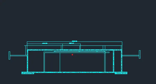
RESULT-