Creating a Floor plan, Footing detail and Isometric view using AutoCad
ANS]
part 1]
AIM - to creating a floor plan footing detail and isometric view using AUTOCAD
INTRODUCTION
The main objective of this assignment is to get in tuch with varius tools in AUTOCAD like the rectangle ,polylines modification tools like copy, move offset and mode like snap moad and ortho mode, these tools will be undrstand by creating a footing detail two bedroom by building cross section of a 2 bedroom building showing foundition detils and isometric view of steps and gable wall
PROCEDURE
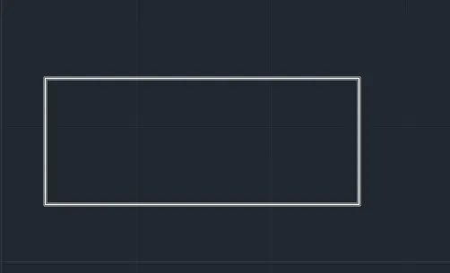
type rectangle in command line and press enter
specify the first corner of the of the rectangle enter D for dimensions
enter the lengh ; 90
enter the widhth ; 25
type L in the command line and press enter
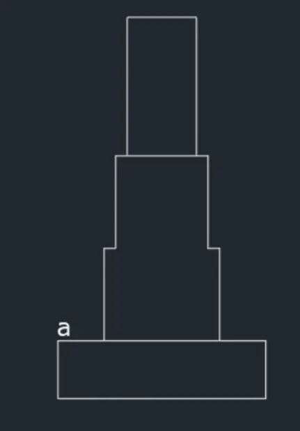
specify the start point a
specify next point :@.20,0
specify next point :@0,40
specify next point :@05,0
specify next point :@0,60
specify next point :@30,0
specify next point :@0,-60
specify next point :@05,0
specify next point :@0,-40
specify next point :@05,0
specify next point :@0,-40
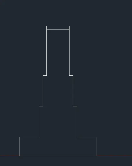
type L the command limne and press enter specify the start point b
specify next point :@0,.05
specify next point :@.30,0
specify next point :@0,-05
type L in the command line and press enter
specify the start point C
specify next point : @0,1
specify next point :@.30,0
specify next point :@0,-1
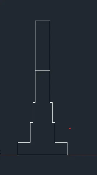
type L in the command line and press the enter
specify the start point D
specify next point :@-.30,0
specify next point :@.05,0
specify next point :@-1.15,0
specify next point :@0,-.15
specify next point :@1.15,0
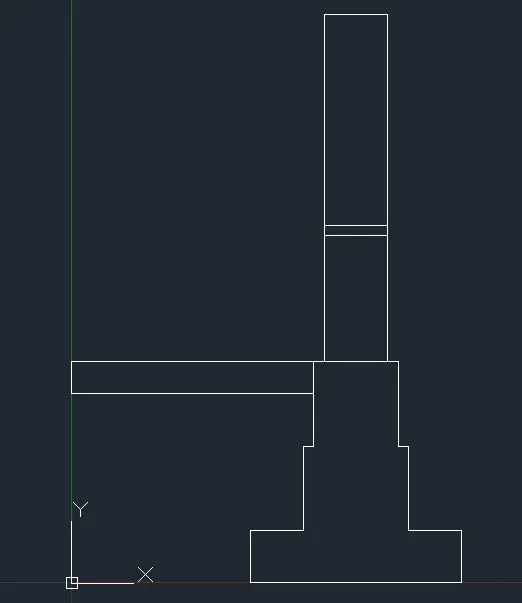
type L in the command line and press enter
specify the next point E
specify next point : @.30,0
specify next point :@0,.15
specify next point :@.30,0
specify next point :@0,.15
specify next point :@.30,0
specify next point :@0,.15
specify next point :@.30,0
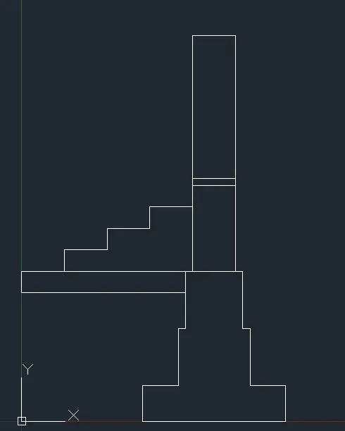
type Lin the command line and press enter
specify the start point f
specify next point :@1,0
specify next point :@o,-.60
specify next point :@-.95,0
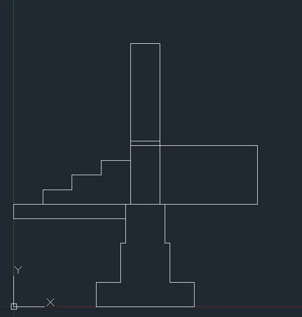
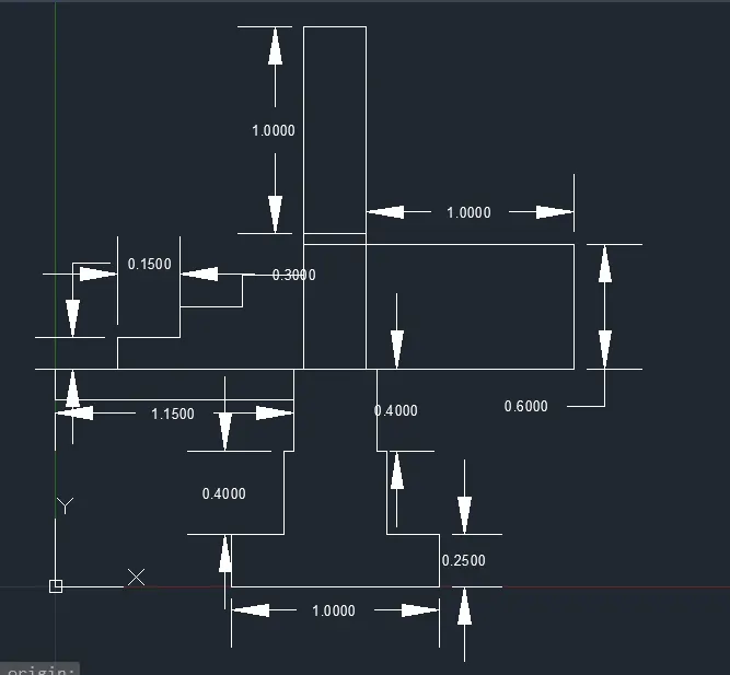
give the dimensions as pre the drawing using dimension command from the command bar
part 2 ]
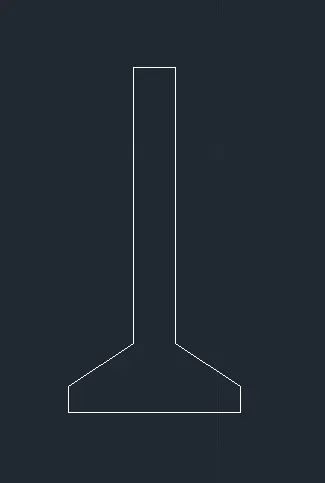
c.s of isolated footing
type rec in the command line and press enter
specify the first corner of the rectangle
enter the D for dimension
enter the length : 1
enter the eidth:.40
specify the other corner

type CHA or CHAMPER in the command line and and press the enter
entre the D for the distance
spceify firet point dichanper distance : .25
spceify second champer distance
select the first first line AB
repeat same stape on opseate side on line CD and BC
specify the point @.04,0
specify the point @0,-1.96
specify the point @-.38,0
specify the point @0,.04
ane then specify the secont poin om line of top then
specify the point @-.04,0
specify the point @0,-1.96
specify the point @.38,0
specify the point @0,.04
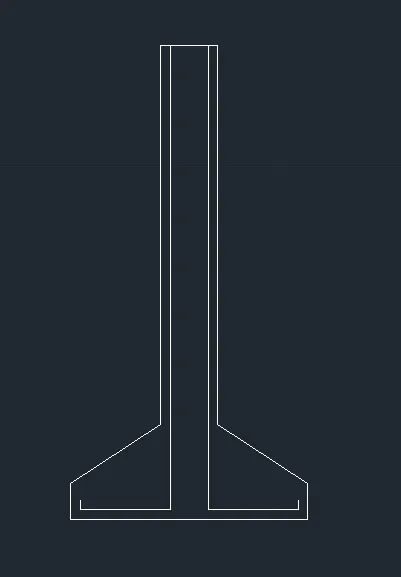
type the L command specify next point @.12,0
type O or offset on the command line and specify the offset distance .20 take the offset
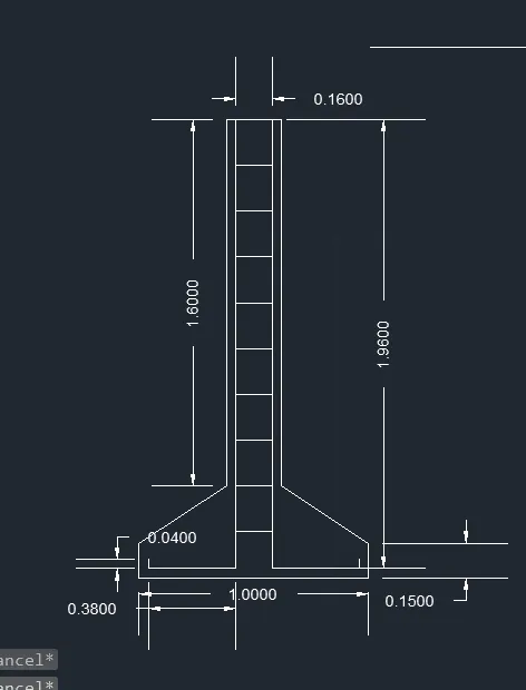
the give the distance of all line
part 3 ]
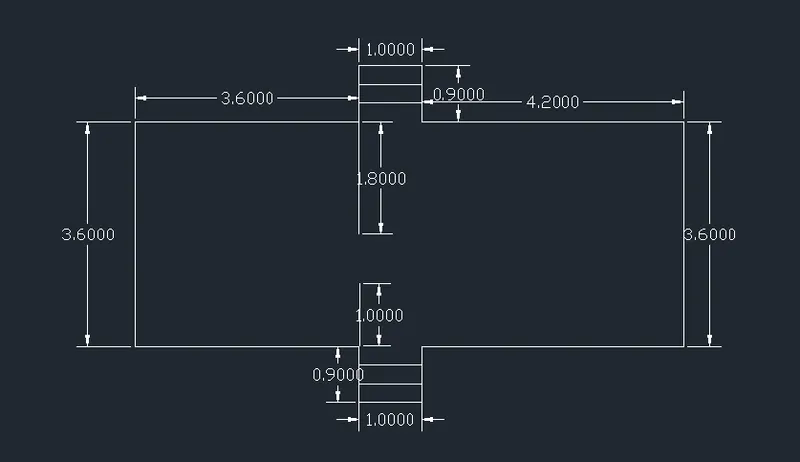
drow the line digram of two bedroom
type the line command and enter
specify the start point A
specify next point :@0,1.80
specify next point :@-3.60,0
specify next point :@0,-3.60
specify next point :@1,0
specify next point :@4.20,0
specify next point :@0,3.60
specify next point :@-4.20,0
specify next point:@-1,0

type PLin the command line and press enter
specify first point of the polyline b
specify next point :@0,.30
specify next point :@1,0
specify next point :@0,-.30
then
type CO in the command line and press entre
select above polyline and specify the base point and paste it as requred
then.
the above two stepes is to be followed here also in the same manner
give the dimesione as per the the drawing using dimesion command from the command bar
the line diagarm of two bed room is completed
part 4]
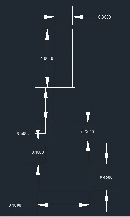
C.S of load bearing wall showing foundaion detalis
PROCEDURE
type L in the command line and press enter
specify the start point a
specify next point :@0,.45
specify next point :@.15,0
specify next point :@0,.40
specify next point :@.05,0
specify next point :@0,.30
specify next point :@.05,0
specify next point :@0,.60
specify next point :@.05,0
specify next point :@0,1
specify next point :@.30,0
specify next point :@0,1
specify next point :@.05,0
specify next point :@0,-.60
specify next point :@.05,0
specify next point :@0,-.30
specify next point :@ .05,0
specify next point :@0,.-40
specify next point :@.15,0
specify next point :@0,-.45
specify next point :@ -.90,0 or c
part 5]
isomtric view of steps
procedure type ds in the command line and prees enter unpick snap on grid on
spceify the next point :1 nw
spceify the next point:.15 n
spceify the next point:1 se
spceify the next point: .15 e
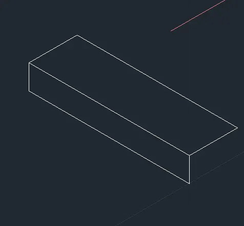
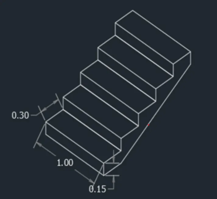
type co in the command and past all 4 steps
then take
spceify the next point: ,15
spceify the next point.30
give the dimision
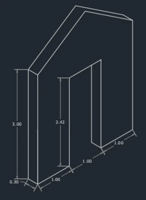
part 5]
isomatric view of gable wall