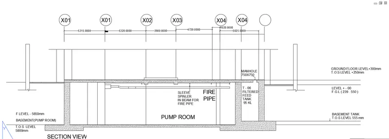
Creation of Multiple viewports, Scaling the drawing and setting in Template in AutoCad
1 . Create a layout of the plan and section A of the project in challenge 7 , using the template tutorial
mArch.dwt in ascale as given in the figure . use the MV command to create thr viewport of the size as
shown in figure . Also , use ATTEDIT command to edit the information in the title block . use A1 size for
the layout . take a plot
Aim : To create the layout of the plan and section A of the project in challenge 7 using the template tutorial - mArch.dwt
using autocad software .
Introduction :
various command used
. layout command
. attedit command
. rectnagle command
. v command
. MV command
. MS command
. PS command
. ST command
. SPACETRANS comand
. PAN command
Procedure :
. click on autocad application and open this application
. open the drawing which is already drawn in challenge 9
. take view command
. click - new - specify view - name plan
. select , define window
. select the window for pland and enter
. take view command > new specify view name > section AA
. select > define widow select the window for section AA and enter
. To create layout right click on layout 1
. select > from template
. click > tutorial - mArch
. right click on new layout > rename
. rename > plan-elevation
. open the plan - section layout
. take rectangle command
. create the two rectangle as shown below
. one rectangle having dimenssion >400,445
. other rectangle having dimenssion > 375 , 445
. take MS command
. take MV command
. select > object and click the one rectangle and Enter and repeated for the another rectangle
. The two view ports are ready
. type v in command bar
. one dialogue box will open
. click > plan > set current > ok
. again do similar process for section AA for other view port
. select Scale >1:50
. select the two view port
. go to properties make it lock
. take ps command
. type > ATTEdit and enter
. select the object as template
. edit the attributes as per requirement
. the attributes is ready as shown below
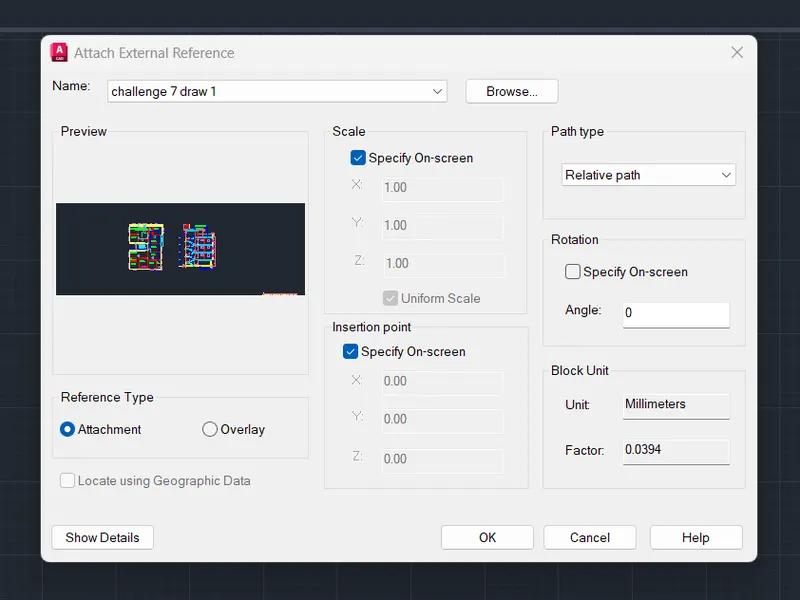
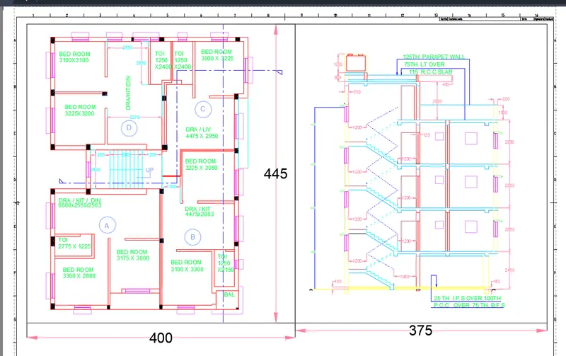
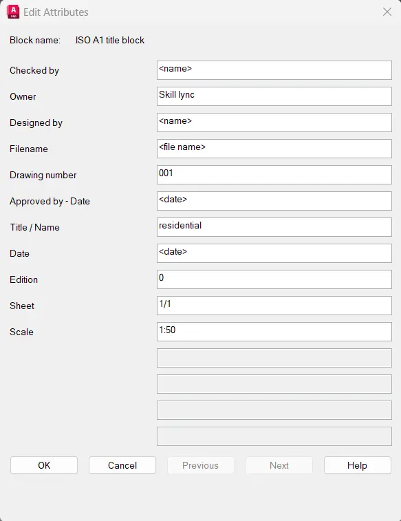
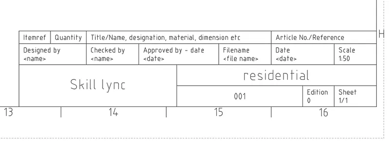
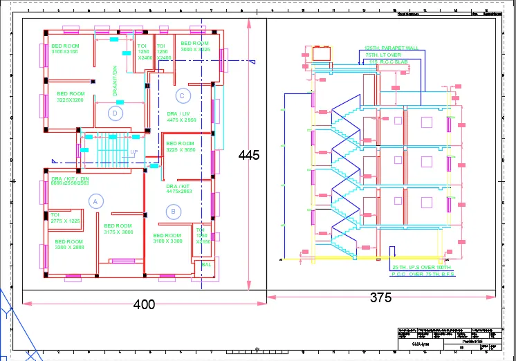
Result : layout is created using template mArch.dwt viewport is created using MV command of size 400x445
and 375x445 mm and scale of viewport is set to 1:50 attributes in the template are edited .
A plot size taken using A1 size
2 . create a layout of the kitchen drawn in challenge 9 as shown in fig . use the scale as shoewn in the fig .
use A4 size pages for the layout . take a plot
Aim : To crate a layout of the kitchen draw in challenge 9 using Autocad software .
Introduction :
various command used
. various command used
. layout command
. attedit command
. rectnagle command
. v command
. MV command
. MS command
. PS command
. ST command
. SPACETRANS comand
. PAN command
Procedure :
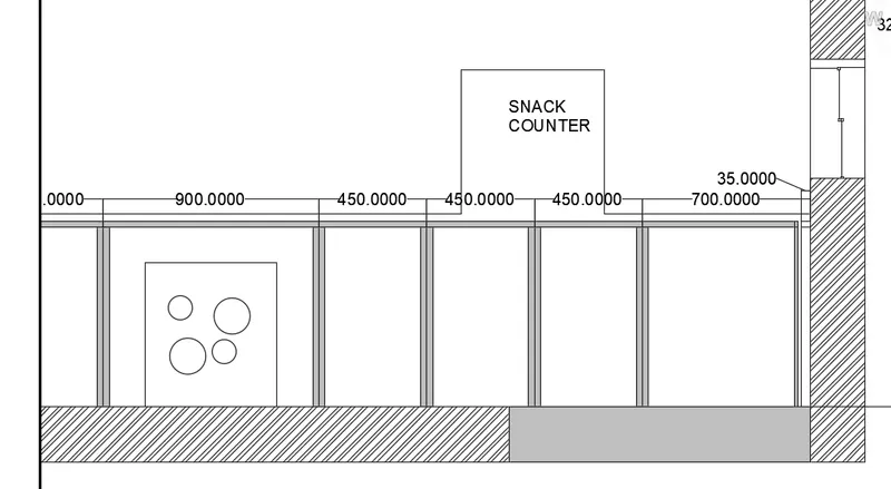
. After drafting layout of kitchen click on layout option display which is present in left bottom or in view panel .
. right click on layout - select page setup manager to set the page for A4
. select plot style as monocromatic
. use ms- model space command to set the model
. divide the layout into 4 equal parts using rectangle
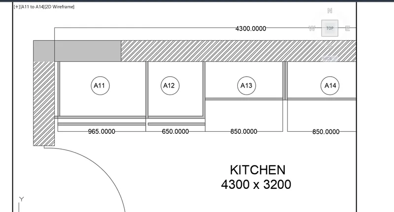
. insert the view to be display into the rectangle
. go to model area
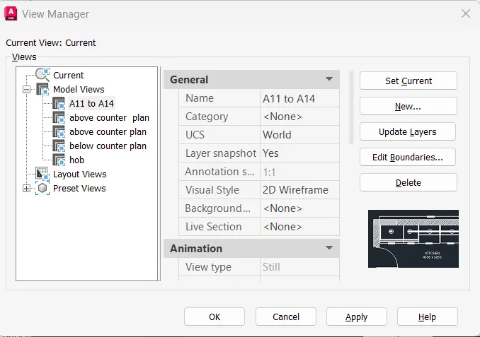
. go to view command , select view enetr the name
. select window specify the view portion and enter
. similary in model space click on third viewport
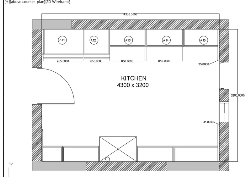
. enter the view above counter plan
. zomm and pan the view port so that the drawing fit in it lock viewport
. go to paper spac and with command T enter text above counter plan and Scale 1:2
. similary in model space click on third viewport
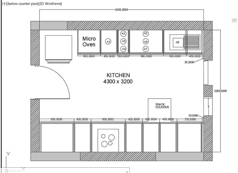
. enter th view below counter plan
. zoom and pan the viewport so that the drawing fit in it . lock viewport
. Go to papaer space and with T command T enetr text as below counter plan and scale 1:2
Result : Different view of kitchen for layout in model space is created layout with four viewport , with A4
sheet is created a plot is created
3. Create a layout of the section created in challenge 9 . use scale as mentioned in the figure .
use MV command create multiple viewport . take a plot
Aim: to create a layout of section created in challenge 9 using autocad software .
Introduction :
various command used
. layout command
. attedit command
. rectnagle command
. v command
. MV command
. MS command
. PS command
. ST command
. SPACETRANS comand
. PAN command
Procedure :
. click on autocad application and open this application
. open the drawing which is already drawn in challehnge 9
. take page setup command
. click> new
. pages setup name > industrial building layout
. set the setting as per shown below and enter
. click > set current and enter
. take view command
. click >new
. specify view name > section view
. select > define window
. select the window for the view and enter
. similary do the same procedure to create other view
. to crate layout right click on new layout > rename > industrial building
. Open the industrialbuilding layout
. type > MV > enter
. specify >3
.select the corner as it will gives following result
. Take MS command
. Take MV command
. select > object
. click the one rectangle and enter
. similarly do for the another rectangle
. the two view ports are ready
. type v in command bar
. one dialgoue box will open
. Click > kitchen - above counter plan > set curent > ok .
. again do similar process for other view port
. select scale > as per view ports shown in drawing
. select the all view ports
. go to properties
. make it lock
. type plot in command bar
. dialogue box will open
. the setting is done as per below
Result : layout of the section of industrial building is craated , viewport is created by MV command and
scale 1:30 and :100 given