Creation of Multiple viewports, Scaling the drawing and setting in Template in AutoCad
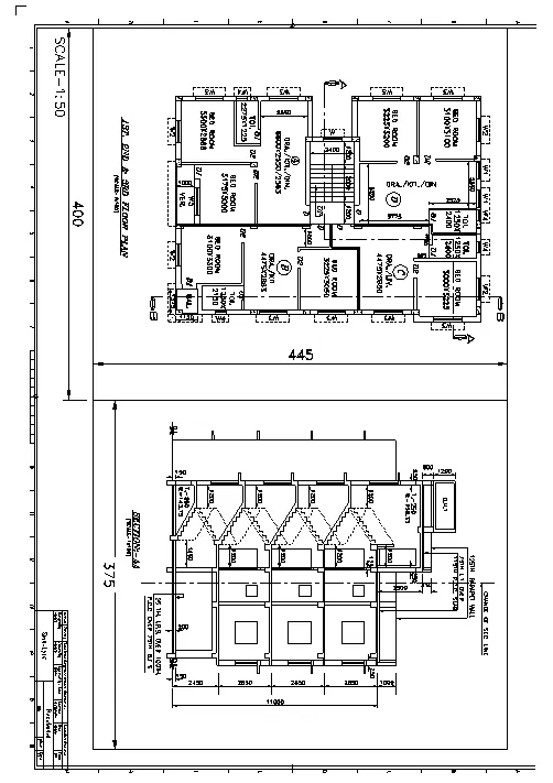
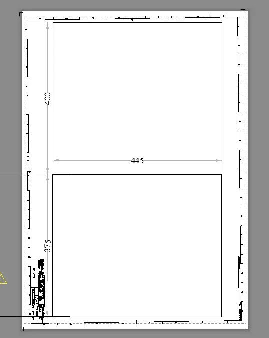
Q-1 Create a layout of the Plan and Section A of the project in Challenges 7, using the template Tutorial-mArch.dwt in a scale as given in the Figure. Use the MV command to create the viewport of the size as shown in Figure. Also, use ATTEDIT command to edit the information in the title block. Use A1 size for the layout. Take a plot.
AIM AND INTRODUCTION :
A layout of the Plan and Section A of the project in Challenges 7, using the template Tutorial-mArch.dwt in a scale as given in the Figure is required to be Created .Tthe viewport of the size as shown in Figure using the MV command is to be created and information in the title block also need to be edited using ATTEDIT command .
PROCEDURE IN DETAIL :
Open auto cad file of challenge 7 of layout is to be created.
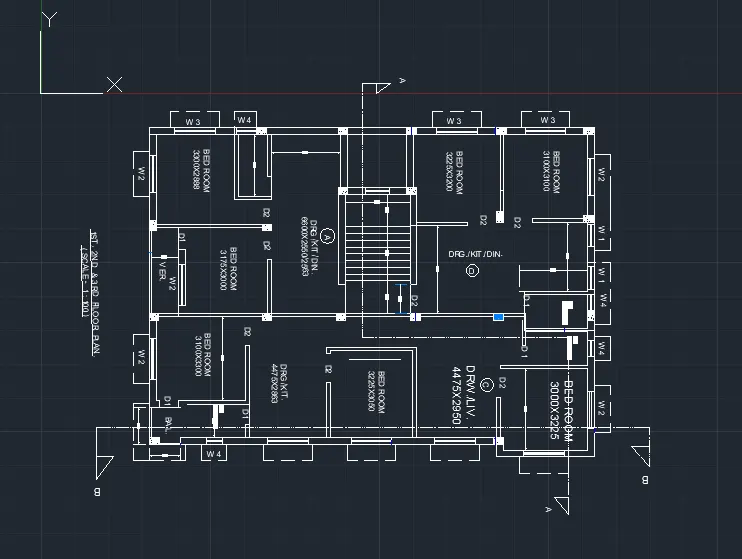
Create Layout using layout command or clicking + sign in status bar situated by the side of default layout-1 &2 and going to page setup Manager by right clicking on layout as shown below and printer/plotter is set up to DWG TOPDF .pc3 , paper size is set to ISO expand A1, plot style to monochrome.stb, Quality to normal and orientation of drawing to potrait as shown below-
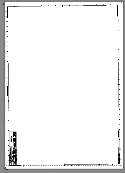
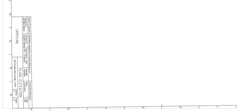
By right clicking layout from popup menu template with name Tutorial-mArch.dwt is selected and information in the title block is edited using ATTEDIT Command as shown below-
Size of viewports are created as given in the figure as shown below-
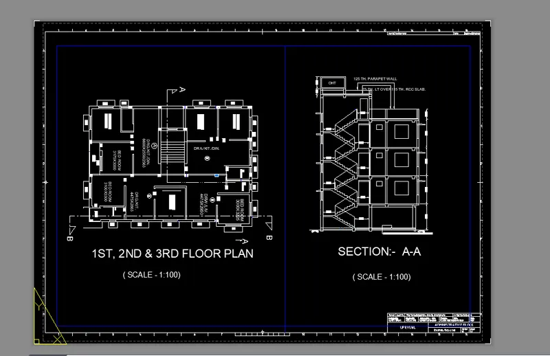
RESULT : Thus
1) A layout of the Plan and Section A of the project in Challenges 7, using the template Tutorial-mArch.dwt in a scale 1:100 as given in the Figure is Created .
2) The viewport of the size as shown in Figure using the MV command is also created and
3) Information in the title block are edited using ATTEDIT command .
-------------------------------- xxxxxxxxxxxxxxxxxxxxx END OF Q1 of challenge-10 xxxxxxxxxxxxxxxxxxx---------------------
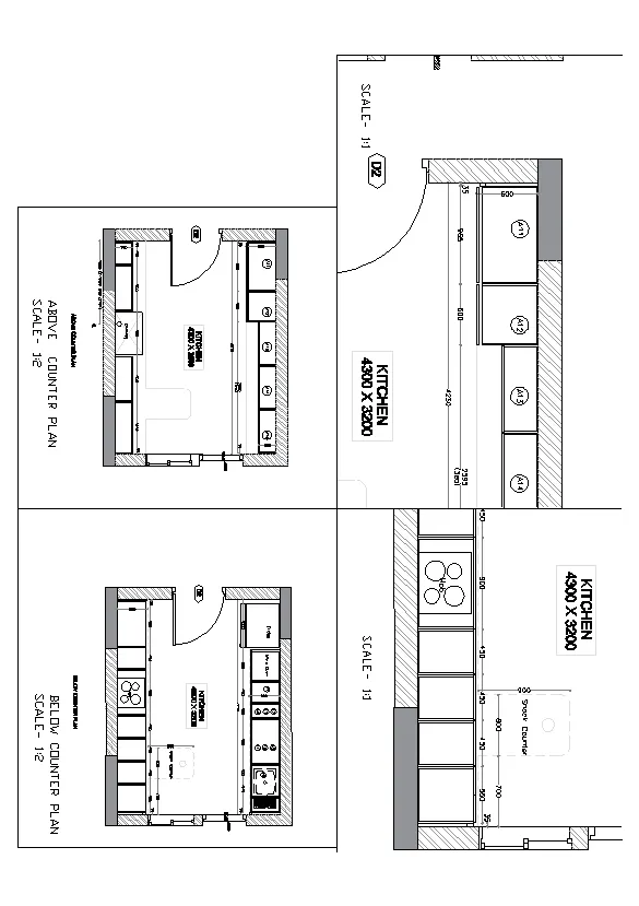
Q2. Create a layout of the Kitchen drawn in Challenge 9 as shown in Figure. Use the scale as shown in the Figure. Use A4 Size page for the layout. Take a plot.
AIM AND INTRODUCTION :
A layout of the Kitchen drawn in Challenge 9 as shown in Figure is to be created USING the scale 1:1 & 1:2 as shown in the Figure on Use A4 Size page
PROCEDURE IN DETAIL : Open auto cad file of challenge 9 of layout is to be created.
Create Layout using layout command or clicking + sign in status bar situated by the side of default layout-1 &2 and going to page setup Manager by right clicking on layout as shown below
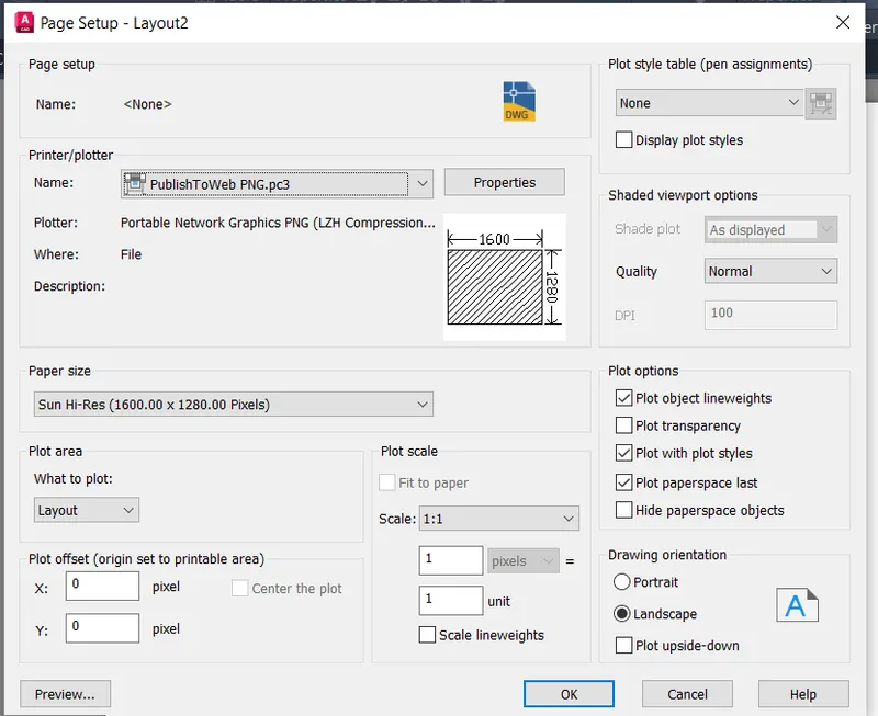
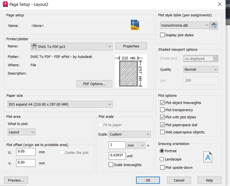
printer/plotter is set up to DWG TOPDF .pc3 , paper size is set to ISO expand A4, plot style to acad.ctb, Quality to normal and orientation of drawing to land scape as shown below-
Scale of drawing is set to 33% of the original size in model in order to accomadate in A4 size lay outwith a scale on layout as 1:1 and 1:2. Using MV command various views (layout) are created. as shown below-
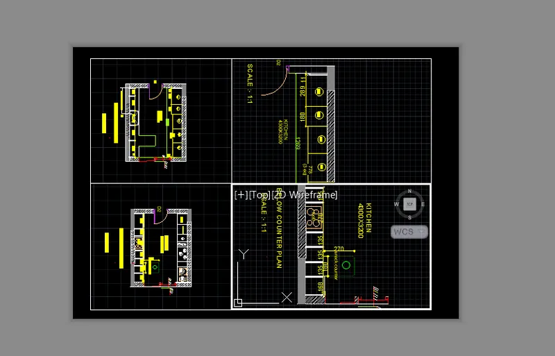
RESULT :Thus layout of the Kitchen drawn in Challenge 9 as shown in Figure is created on A4 size paper on scale 1:1 and 1:2. CAD file ia attached with name ACCH10Q2RR for reference.
xxxxxxxxxxxxxxxxxx------------------------xxxxxxxxxxxxx END OF Q-2 OF CHALLENGE-10 ------xxxxxxxxxxxxxxxxxx----------
Q-3. Create a layout of the section created in Challenges 9.
Use scale as mentioned in the Figure. Use MV command create multiple viewports. Take a plot.
AIM AND INTRODUCTION :
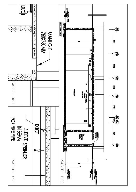
A layout of the section created in Challenges 9 is required to be created using scale as mentioned in the Figure
and using MV command multiple viewports are to be created.
PROCEDURE IN DETAIL :
Open auto cad file of challenge 9 of layout is to be created.
Create Layout using layout command or clicking + sign in status bar situated by the side of default layout-1 &2 and going to page setup Manager by right clicking on layout as shown below -
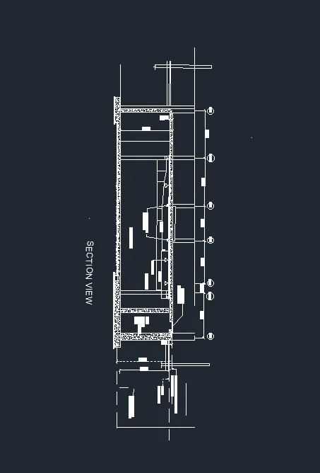
Create Layout using layout command or clicking + sign in status bar situated by the side of default layout-1 &2 and going to page setup Manager by right clicking on layout as shown below and
printer/plotter is set up to DWG TOPDF .pc3 , paper size is set to ISO expand A4, plot style to monochrome.stb, Quality to normal and orientation of drawing to potrait as shown below-
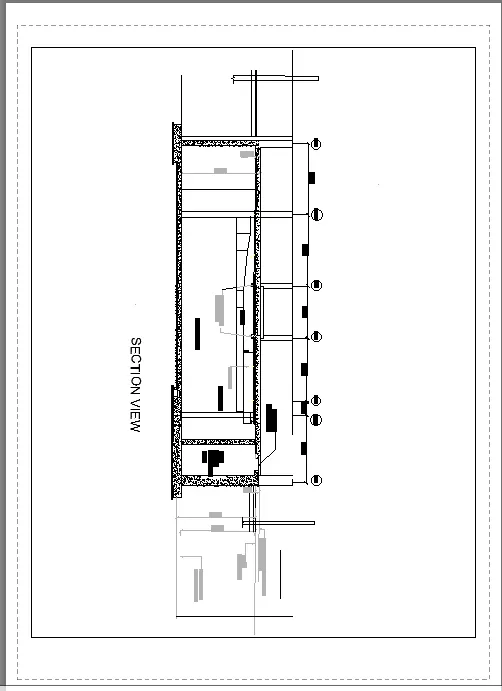
MV command is used to create viewport ( Here single view por is created as per given figure. Drawing of the model appear in viw port by double clicking inside the boundary of layout as shown below-
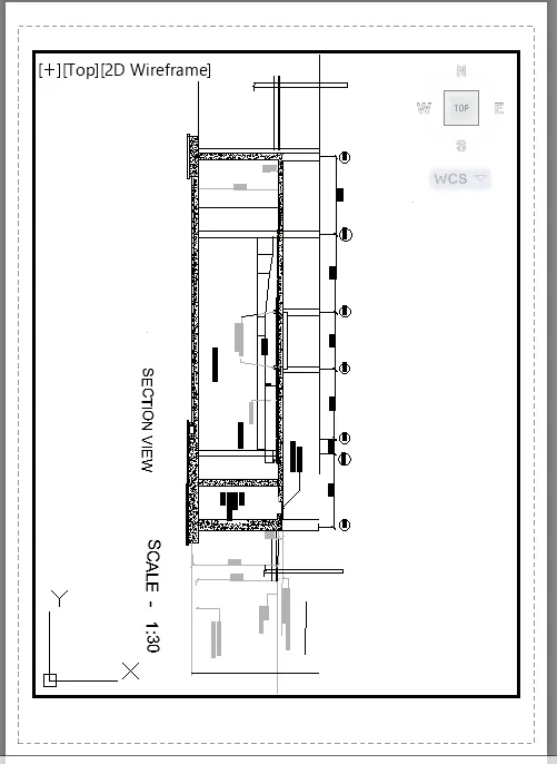
MT Command is used to write scale - 1:30 below at the right corner of the drawing as shown-
RESULT :
Thus layout of the section in Challenges 9 is created with scale 1:30 as mentioned in the Figure. .DWG file is also attached with name as ACCH10Q (R).dwg
--------------------------------------xxxxxxxxxxxxxxx END OF Q-3 OF CHALLENGE-10 xxxxxxxxxxxxxxxx-----------------------