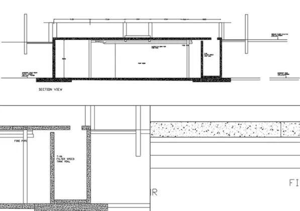
Creation of Multiple viewports, Scaling the drawing and setting in Template in AutoCad
1. Aim :
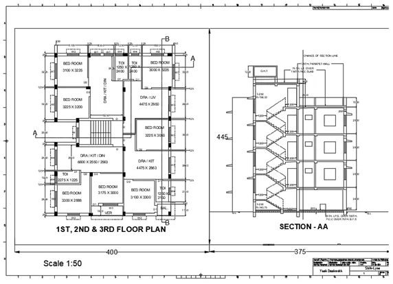
Create a layout of the Plan and Section A of the project in Challenges 7, using the template Tutorial mArch.dwt in a scale as given in the Figure.
Introduction:
The general commands used for drawing the building is as follows:
1. Line
2. Polygon
3. Rectangle
4. Circle
5. Erase
6. Copy
7. Trim
8. Mirror
9. Offset
10. Extend
11. Array
12. Move
13. Rotate
14. Dimension
15. Text
16. Fillet
The dimensions :
- For external wall - 250mm
- For internal wall - 125mm
- For Staircase: - Treads: 250mm, Rise: 150mm
The assumed dimensions:
For Windows:
- W-1000 X 1500
- W1-900 X 1200 o W2-1200 X 1200
- W3-1500 X 1200
- W4-700 X 500
For Doors:
- D-1000 X 2000
- D1-750 X 2000
- D2-900 X 2000
Procedure :
- Click on AutoCAD application and open this application
- Open the drawing which is already drawn in challenge 9
- Take view command
- Click > New
- Specify view name > Plan
- Select Define window
- Select the window for plan
- Enter
- Take view command
- Click > New
- Specify view name> SectionAA
- Select Define window
- Select the window for Section AA
- Enter
- To create layout
- Right click on Layout1
- Select > From Template
- Click > Tutorial-mArch
- Ok
- Right click on new layout > Rename
- Rename > Plan-Elevation
- Open the Plan-Section layout
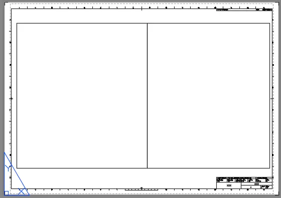
- Take rectangle command
- Create the two rectangle as shown below
- One rectangle having dimension > 400, 445
- Other rectangle having dimension > 375, 445
- Take Ms command
- Take MV command
- Select > Object
- Click the one rectangle
- Enter
- Similarly do for the another rectangle
- The two view ports are ready
- Type v in command bar
- One dialogue box will open
- Click> Plan> Set current > Ok
- Again do similar process for Section AA for other view port
- Select Scale > 1/5 * O
- Select the two view ports
- Go to properties
- Make it lock
- Take Ps command
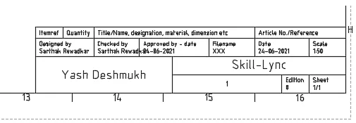
- Type> ATTEdit
- Enter
- Select the object as template
- Edit the attribute as per requirement
- The attribute is ready as shown below
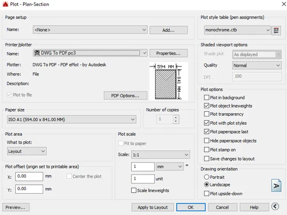
- Type plot in command bar
- Dialogue box will open
- The setting is done as per below
- The layout is ready
Result :
2. Aim :
To create the layout of the kitchen as shown below by using the view ports.
Procedure :
- Click on AutoCAD application and open this application
- Open the drawing which is already drawn in challenge 9
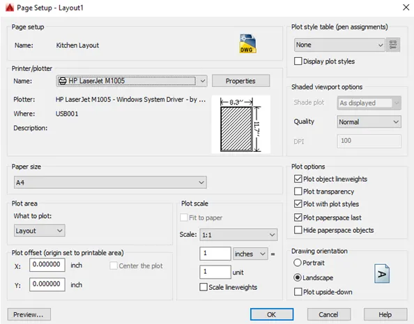
- Take page setup command
- Click > New
- Page setup Name> Kitchen layout
- Set the settings as per shown below
- Enter
- Click> Set current
- Enter
- Take view command
- Click > New
- Specify view name > Kitchen-Above Counter plan
- Select > Define window
- Select the window for plan
- Enter
- Similarly do the same procedure to create other views
- To create layout
- Right click on Layout1
- Right click on new layout > Rename
- Rename> Kitchen
- Open the Kitchen layout
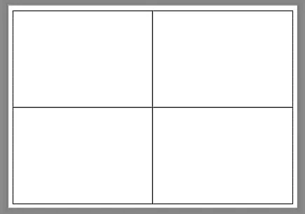
- Type> MV > enter
- Specify > 4
- Select the corner as it will gives following results
- Take Ms command
- Take MV command
- Select > Object
- Click the one rectangle
- Enter
- Similarly do for the another rectangle
- The two view ports are ready
- Type v in command bar
- One dialogue box will open
- Click Kitchen-Above counter Plan> Set current > Ok
- Again do similar process for other view port
- Select Scale > as per view ports shown in drawing
- Select the all view ports
- Go to properties
- Make it lock
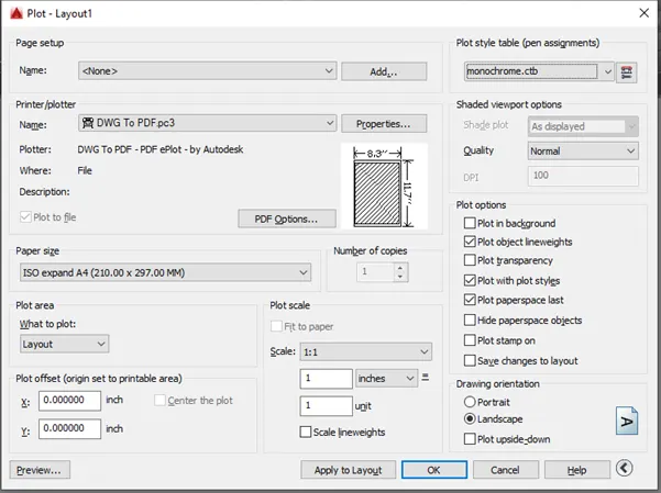
- Type plot in command bar
- Dialogue box will open
- The setting is done as per below
- The layout is ready
Result :
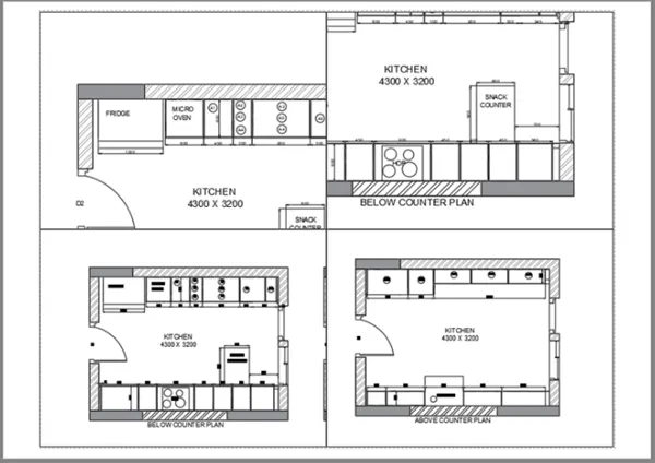
3. Aim :
To create the layout of the Industrial Building as shown below by using the view ports.
Procedure :
- Click on AutoCAD application and open this application
- Open the drawing which is already drawn in challenge 9
- Take page setup command
- Click > New
- Page setup Name> Industrial building layout
- Set the settings as per shown below
- Enter
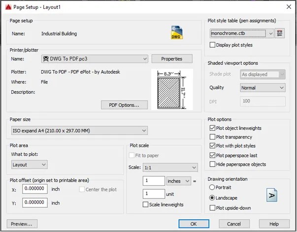
- Click > Set current
- Enter
- Take view command
- Click > New
- Specify view name > Section View
- Select > Define window
- Select the window for view
- Enter
- Similarly do the same procedure to create other views
- To create layout
- Right click on Layout1
- Right click on new layout > Rename
- Rename > Industrial Building
- Open the Industrial Building layout
- Type > MV > enter
- Specify > 3
- Select the corner as it will gives following results
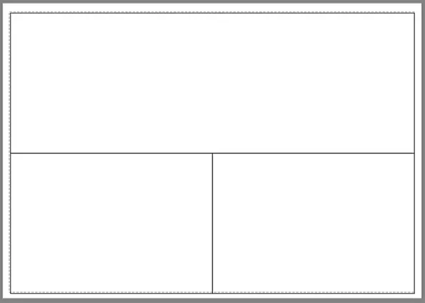
- Take Ms command
- Take MV command
- Select Object
- Click the one rectangle
- Enter
- Similarly do for the another rectangle
- The two view ports are ready
- Type v in command bar
- One dialogue box will open
- Click > Kitchen-Above counter Plan> Set current > Ok
- Again do similar process for other view port
- Select Scale as per view ports shown in drawing
- Select the all view ports
- Go to properties
- Make it lock
- Type plot in command bar
- Dialogue box will open
- The setting is done as per below
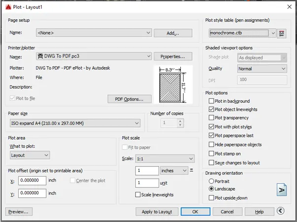
- The layout is ready
Result :