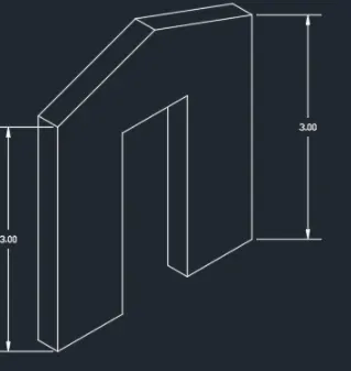
Creating a Floor plan, Footing detail and Isometric view using AutoCad
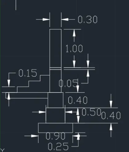
1. Aim:
To create a cross-section of load-bearing wall overspread footing using AutoCAD.
Procedure:
- Open AutoCAD.
- In the command prompt type QNEW
- Click on imperical template, advanced setup, decimal.
- In the command prompt type units.
- Type-decimal.precisionn-0.00, angle-decimal degree.
- In the command prompt type REC
- Specify first corner point 1,1
- Click on the dimensions
- Specify length of the rectangle 0.90
- Specify width of the rectangle 0.25
- In the command prompt type REC
- Specify first comer point 1.2.1.25
- Click on the dimensions.
- Specify length of the rectangle 0.5
- Specify width of the rectangle 0.4
- In the command prompt type REC
- Specify first corner point 1.25.1.65
- Click on the dimensions
- Specify the length of rectangle 0.4
- Specify width of rectangle 0.4
- In the command prompt type REC
- Specify first corner point 1.3,2.05
- Click on the dimensions
- specify length of the rectangle 0.3
- specify width of the rectangle 0.6
- In the command prompt type REC
- specify first corner point 1.3,2.65
- Click on the dimensions
- Specify length of the rectangle 0.3
- Specify width of the rectangle 0.05
- In the command prompt type REC
- Specify first corner point 1.3,2.7
- Click on the dimensions
- Specify length of the rectangle 0.3
- Specify width of the rectangle 1
- In the command prompt type line specify point 1.3,2.05
- Specify the distance @1.15<180
- Specify the distance @0.15<270
- Specify the distance @1.15<0
- In the command prompt type line
- Specify point 0.15,2.05
- Specify the distance @0.3<0
- Specify the distance @0.15<90
- Specify the distance @0.3<0
- Specify the distance @0.15<90
- Specify the distance @0.3<0
- Specify the distance @0.15<90
- Specify the distance @0.3<0
Result:
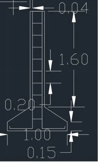
2. Aim: To create a cross-section of Isolated Footing.
Procedure:
- Open AutoCAD.
- In the command prompt type QNEW.
- Click on imperical template, advanced setup, decimal.
- In the command prompt type units.
- Type-decimal.precisionn=0.00, angle-decimal degree.
- In the command prompt type line
- Specify first point 1,1
- Specify the distance @0.15<90
- Specify the distance @0.25-90 (line 1)
- Specify the distance @0.38-0 (line 2)
- Join the line 1 and 2 and delete lines 1&2.
- In the command prompt type line
- Specify first point 1.38,1.4
- Specify the distance @1.6<90
- Specify the distance @0.24<0
- Specify the distance @1.6<270 specify the distance @0.38<0 (line 1)
- Specify the distance @0.25<270 (line 2)
- Join line 1&2 and delete line 1&2
- In the command prompt type line
- Specify first point 2,1.15
- Specify the distance @0.15<270
- In the command prompt type close
- In the command prompt type line
- Specify first point 1.04,1.08
- Specify the distance @0.04<270
- Specify the distance @0,38<0
- Specify the distance @1.96-90
- Specify the distance @1<0
- Specify the distance @1.96<270
- Specify the distance @0.38<0
- In the command prompt type offset
- Click on multiple
- Specify the distance of 0.2
Result:
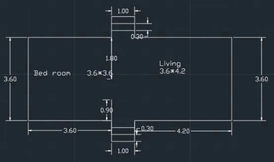
3. Aim:
To create the line diagram of Two-Bedroom Building
Procedure:
- Open AutoCAD.
- In the command prompt type QNEW.
- Click on impirical template, advanced setup, decimal.
- In the command prompt type units.
- Type=decimal,precision-0.00, angle-decimal degree.
- In the command prompt type line
- Specify the first point 3,3
- Specify the distance @3.60<0
- Specify the distance @0.9<270
- Specify the distance @1<0
- Specify the distance @0.9+90
- Specify the distance @4.20<0
- Specify the distance @3.6<90
- Specify the distance @4.2<180
- Specify the distance @0.9-90
- Specify the distance @1<180
- Specify the distance @0.9-270
- Specify the distance @3.6<180
- Specify the distance @3.6<270
- In the command prompt type line
- Specify first point 6.6,3
- Specify the distance @0.9-90
- Enter
- In the command prompt type line
- Specify first point 6.6,6.6
- Specify the distance @1.8<270
- Enter
- In the command prompt type offset
- Specify the distance of 0.3 at steps
Result:
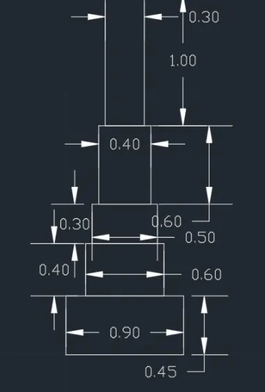
4. Aim:
To create a cross-section of load-bearing wall overspread footing using AutoCAD.
Procedure:
- Open AutoCAD.
- In the command prompt type QNEW.
- Click on imperical template, advanced setup, decimal.
- In the command prompt type units.
- Type-decimal.precisionn=0.00, angle-decimal degree.
- In the command prompt type REC
- Specify first corner point 1,1
- Click on dimensions
- Specify the length of the triangle 0.9
- Specify the width of the triangle 0.45
- In the command prompt type REC
- Specify first corner point 1.15,1.45
- Click on dimensions
- Specify the length of the triangle 0.6
- Specify the width of the triangle 0.4
- In the command prompt type REC
- Specify first comer point 1.2.1.85
- Click on dimensions
- Specify the length of the triangle 0.5
- Specify the width of the triangle 0.3
- In the command prompt type REC
- Specify first corner point 1.25.2.15
- Click on dimensions
- Specify the length of the triangle 0.4
- Specify the width of the triangle 0.6
- In the command prompt type REC
- Specify first corner point 1.3,2.75
- Click on dimensions
- Specify the length of the triangle 0.3
- Specify the width of the triangle 1.0
- Enter
Result:
Aim:
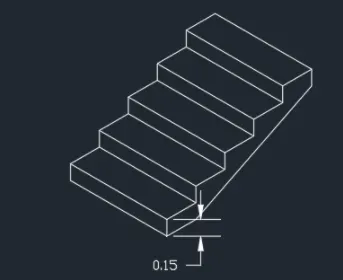
To create an Isometric view of steps.
Procedure:
- Open AutoCAD.
- Enter units in the command box.
- Select Decimals in type, 0.00 in precision and meters in units.
- Type DS in command box
- Put snap Off and grid off. click isometric snap on.
- Switch on orthomode.
- Click isometric left in the status bar.
- Enter L in the command box.
- In the command box type line
- Enter first point 3,3.
- Place the cursor upwards and enter 0.15.
- Place the cursor right side and enter 1.00
- Place the cursor downside and enter 0.15
- Place the cursor left side and enter 1.00
- Enter L in the command box
- Click on the upper top corner of the diagram
- Enter 0.3 as the first point in command box.
- Enter CO in command box which is copy.
- Select the line 0.3 in length.
- And repeat these dimensions up to 4 steps.
- Enter line on command box 3.3
- Place the cursor right side and enter 0.15
- And enter the line at end of the step
- Place the cursor downside and enter 0.15
- And join these two lines
Result:
6. Aim:
To draw the isometric view of gable wall.
Procedure:
- Open AutoCad
- In the command prompt type QNEW.
- Click on imperical template, advanced setup, decimal.
- In the command prompt type units.T
- Type -decimal, precision-0.00, angle-decimal degree.
- In the command prompt type ds.
- In drafting settings off snap and grid.
- Select on isometric snap.
- Keep ortho (f8) on.
- In the command prompt type line.
- Specify the point or select a point.
- Press f5 to get the line in the desired direction.
- In the command prompt type the required distance.
Result: