Creation of Multiple viewports, Scaling the drawing and setting in Template in AutoCad
1. Create a layout of the Plan and Section A of the project in Challenges 7, using the template Tutorial-mArch.dwt in a scale as given in the Figure. Use the MV command to create the viewport of the size as shown in Figure. Also, use ATTEDIT command to edit the information in the title block. Use A1 size for the layout. Take a plot.
Answer:
Aim: To Create a layout of the Plan and Section A of the project in Challenges 7, using the template Tutorial-mArch.dwt in a scale as given in the Figure. Use the MV command to create the viewport of the size as shown in Figure. Also, use ATTEDIT command to edit the information in the title block. Use A1 size for the layout. Take a plot.
Command Used: Viewport, MV MultiView, ATTEDIT
Procedure:
1. To convert AutoCAD file into PDF, to take prints and send it to site.
2. Go to the existing file of drawing which to convert into pdf i.e modal space sheet
3. Below there is a layout click on the layout and right click to rename the sheet.(For E.g Plan, Elevation, Section..etc)
4. Use the command Multiview to create as many as drawing view of the sheet, select fisrt corner and then opposite corner.
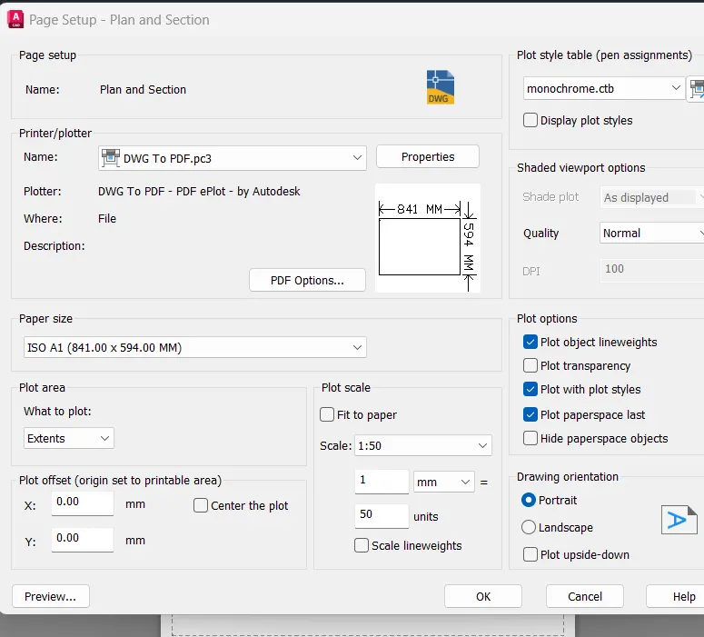
5. Right click on renamed layout as select Page setup manager - choose dwg to pdf - Page size ISO A1(for MM) for the present sheet as per the question information given
6. Orientation to be as Portrait
7. Plot layout scale 1:50
8. Plot style as penassignment
9. For drawing to be printed as with the same colour as per the AutoCAD drawing select monocrome. ctb.
10. To edit model space give the command MS and zoom it to the required data.
11. To edit the paper use the command PS i.e Paper Movement
12. Right click on the layout select plot it will ask you for final print checklist then say ok
13. Now type a name of the Pdf sheet and save it in PC.
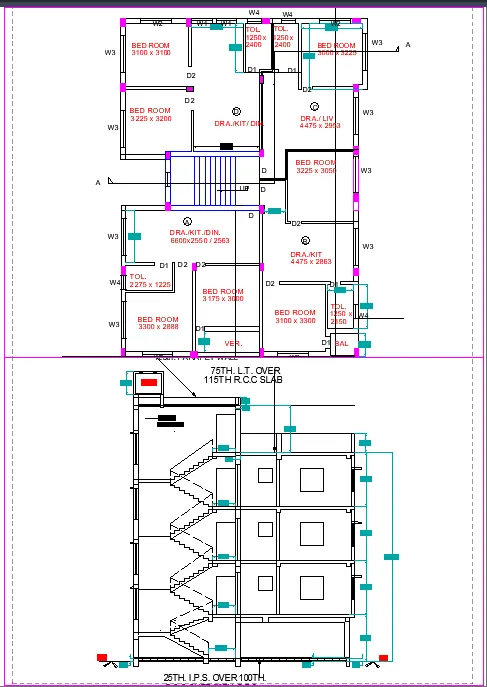
Result: Layout of plan and section is created as shown below and saved as pdf file.
AutoCAD Result:
2. Create a layout of the Kitchen drawn in Challenge 9 as shown in Figure. Use the scale as shown in the Figure. Use A4 Size page for the layout. Take a plot.
Answer:
Aim: To Create a layout of the Kitchen drawn in Challenge 9 as shown in Figure. Use the scale as shown in the Figure. Use A4 Size page for the layout. Take a plot.
Command Used: Viewport, MV MultiView, ATTEDIT
Procedure:
1. To convert AutoCAD file into PDF, to take prints and send it to site.
2. Go to the existing file of drawing which to convert into pdf i.e modal space sheet
3. Below there is a layout click on the layout and right click to rename the sheet.(For E.g Plan, Elevation, Section..etc)
4. Use the command Multiview to create as many as drawing view of the sheet, select fisrt corner and then opposite corner.
5. Right click on renamed layout as select Page setup manager - choose dwg to pdf - Page size ISO A4(for MM) for the present sheet as per the question information given
6. Orientation to be as landscape
7. Plot layout scale 1:1 and 1:2
8. Plot style as penassignment
9. For drawing to be printed as with the same colour as per the AutoCAD drawing select monocrome. ctb.
10. To edit model space give the command MS and zoom it to the required data.
11. To edit the paper use the command PS i.e Paper Movement
12. Right click on the layout select plot it will ask you for final print checklist then say ok
13. Now type a name of the Pdf sheet and save it in PC.
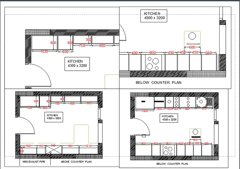
Result: Layout of Kitchen Layout is created as shown below and saved as pdf file.
Result:
AutoCAD Result:
3. Create a layout of the section created in Challenges 9. Use scale as mentioned in the Figure. Use MV command create multiple viewports. Take a plot.
Answer:
Aim: To Create a layout of the section created in Challenges 9. Use scale as mentioned in the Figure. Use MV command create multiple viewports. Take a plot.
Command Used: Viewport, MV MultiView, ATTEDIT
Procedure:
1. To convert AutoCAD file into PDF, to take prints and send it to site.
2. Go to the existing file of drawing which to convert into pdf i.e modal space sheet
3. Below there is a layout click on the layout and right click to rename the sheet.(For E.g Plan, Elevation, Section..etc)
4. Use the command Multiview to create as many as drawing view of the sheet, select fisrt corner and then opposite corner.
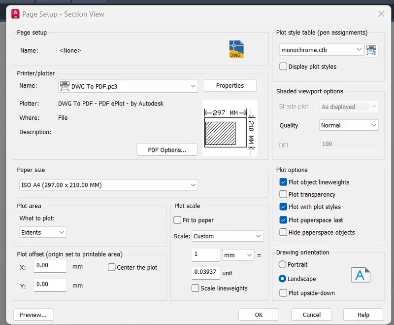
5. Right click on renamed layout as select Page setup manager - choose dwg to pdf - Page size ISO A4(for MM) for the present sheet as per the question information given
6. Orientation to be as landscape
7. Plot layout scale 1:2
8. Plot style as penassignment
9. For drawing to be printed as with the same colour as per the AutoCAD drawing select monocrome. ctb.
10. To edit model space give the command MS and zoom it to the required data.
11. To edit the paper use the command PS i.e Paper Movement
12. Right click on the layout select plot it will ask you for final print checklist then say ok
13. Now type a name of the Pdf sheet and save it in PC.
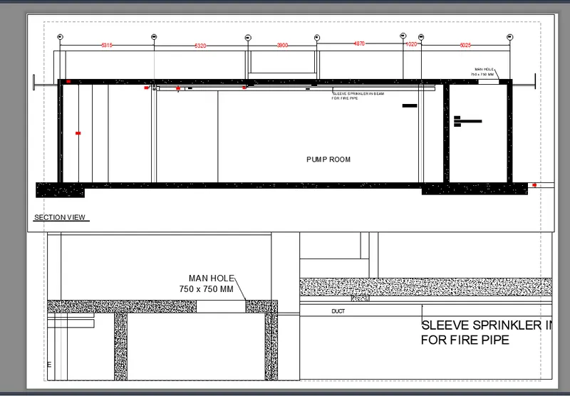
Result: Layout of section view is created as shown below and saved as pdf file.
Result:
AutoCAD Result: