Creation of Multiple viewports, Scaling the drawing and setting in Template in AutoCad
1) AIM
To create a layout in challenge 7 and using the template option using autocad.
INTRODUCTION
This plan and section is created using autocad and setting the layout procedure is explained in detail in each steps and the commands are used in this drawing are.
COMMANDS USED IN THIS DRAWING
- L- LINE
- F8- ORTHO MODE
- GRIDMODE
- F10 - POLAR TRACKING
- ST - STYLE TEXT
- DT-SINGLE TEXT
- T- MULTITEXT
- C- CIRCLE
- CO-COPY
- M-MOVE
- T- TEXT
- TR- TRIM
- O-OFFSET
- F- FILLET
- D-DIMENSION STYLE
- REC-RECTANGLE
- DIMLINEAR
- DIMCONT
- DIMBASE
- LEADER
- QLEADER
- SC-SCALE
- LA-layers
- ADC-design center
- B-Block
- I-insert
- Xl-xline
- H-hatch
- xref
- layout
- mv- mview
- ms- model space
- ps- paper space
PROCEDURE
- open autocad file in windows desktop.
- a dialog box will open it shows startup from scratch.
- click the radio button imperial to start the project.
- in command box type gridmode to show the gridmode by typing 1 in the command box
- type F8 to get ortho on.
- type limmax to set the maximum layout.
- type llmits to set the layout.
- TYPE UN FOR UNITS and set to DECIMAL.
Step 1.
SETTING OF A LAYOUT
TYPE - layout set new name to the layout.
e-erase the object on the layout.
type Mv- multpile view port set the layout size to zoom in the view.
type MS- to set the model space in the layout.
type ps- paper space to set the paper in a size of the layout.
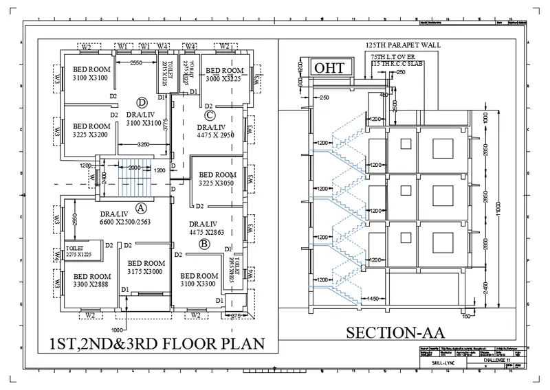
scaling to size to model space to 1:100
as shown in fig below.
STEP 2
After setting layout
PAGE SETUP
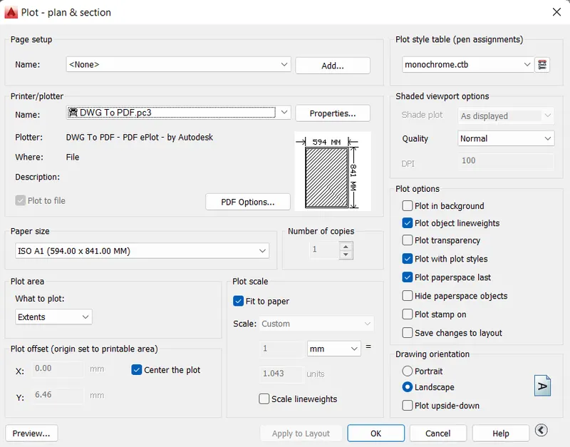
press ctrl+P to print the page in the setup as per size in the PDF
to take prinout as per the size.
this prinout layout is set to A1 the page is setup to layout A1
how the dialog box is shown below for the printer setup
STEP 3
after the page setup
in the preview option you can see how the layout is came.
after setting is done the files will save to PDF to the size.
the files you can save it as PDF save in a folder.
RESULT . The following plot is set to layout using templates is completed.
2)AIM
To create a kitchen layout using autocad.
INTRODUCTION
This kitchen layout is created using autocad and setting the layout procedure is explained in detail in each steps and the commands are used in this drawing are.
COMMANDS USED IN THIS DRAWING
- L- LINE
- F8- ORTHO MODE
- GRIDMODE
- F10 - POLAR TRACKING
- ST - STYLE TEXT
- DT-SINGLE TEXT
- T- MULTITEXT
- C- CIRCLE
- CO-COPY
- M-MOVE
- T- TEXT
- TR- TRIM
- O-OFFSET
- F- FILLET
- D-DIMENSION STYLE
- REC-RECTANGLE
- DIMLINEAR
- DIMCONT
- DIMBASE
- LEADER
- QLEADER
- SC-SCALE
- LA-layers
- ADC-design center
- B-Block
- I-insert
- Xl-xline
- H-hatch
- xref
- layout
- mv- mview
- ms- model space
- ps- paper space
- pagesetup
PROCEDURE
- open autocad file in windows desktop.
- a dialog box will open it shows startup from scratch.
- click the radio button imperial to start the project.
- in command box type gridmode to show the gridmode by typing 1 in the command box
- type F8 to get ortho on.
- type limmax to set the maximum layout.
- type llmits to set the layout.
- TYPE UN FOR UNITS and set to DECIMAL.
Step 1.
SETTING OF A LAYOUT
TYPE - layout set new name to the layout.
e-erase the object on the layout.
type Mv- multpile view port set the layout size to zoom in the view.
type MS- to set the model space in the layout.
type ps- paper space to set the paper in a size of the layout.
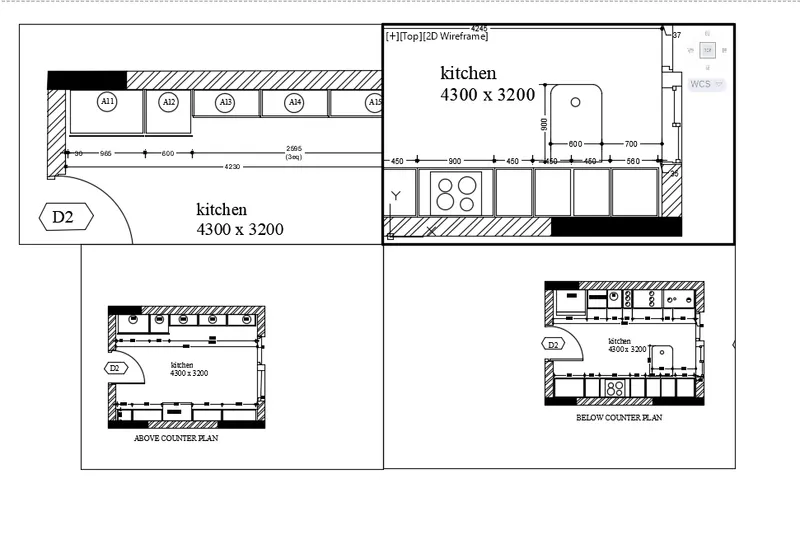
scaling to size to model space to 1:100
as shown in fig below.
STEP 2
After setting layout
press ctrl+P to print the page in the setup as per size in the PDF
to take prinout as per the size.
this prinout layout is set to A1 the page is setup to layout A4 size.
how the dialog box is shown below for the printer setup.
STEP 3
after the page setup
in the preview option you can see how the layout is came.
after setting is done the files will save to PDF to the size.
save the in the folder
RESULT . The following plot is set to layout using templates is completed.
3)AIM
To create a sectional view layout using autocad.
INTRODUCTION
This sectional view layout is created using autocad and setting the layout procedure is explained in detail in each steps and the commands are used in this drawing are.
COMMANDS USED IN THIS DRAWING
- L- LINE
- F8- ORTHO MODE
- GRIDMODE
- F10 - POLAR TRACKING
- ST - STYLE TEXT
- DT-SINGLE TEXT
- T- MULTITEXT
- C- CIRCLE
- CO-COPY
- M-MOVE
- T- TEXT
- TR- TRIM
- O-OFFSET
- F- FILLET
- D-DIMENSION STYLE
- REC-RECTANGLE
- DIMLINEAR
- DIMCONT
- DIMBASE
- LEADER
- QLEADER
- SC-SCALE
- LA-layers
- ADC-design center
- B-Block
- I-insert
- Xl-xline
- H-hatch
- xref
- layout
- mv- mview
- ms- model space
- ps- paper space
- pagesetup
PROCEDURE
- open autocad file in windows desktop.
- a dialog box will open it shows startup from scratch.
- click the radio button imperial to start the project.
- in command box type gridmode to show the gridmode by typing 1 in the command box
- type F8 to get ortho on.
- type limmax to set the maximum layout.
- type llmits to set the layout.
- TYPE UN FOR UNITS and set to DECIMAL.
Step 1.
SETTING OF A LAYOUT
TYPE - layout set new name to the layout.
e-erase the object on the layout.
type Mv- multpile view port set the layout size to zoom in the view.
type MS- to set the model space in the layout.
type ps- paper space to set the paper in a size of the layout.
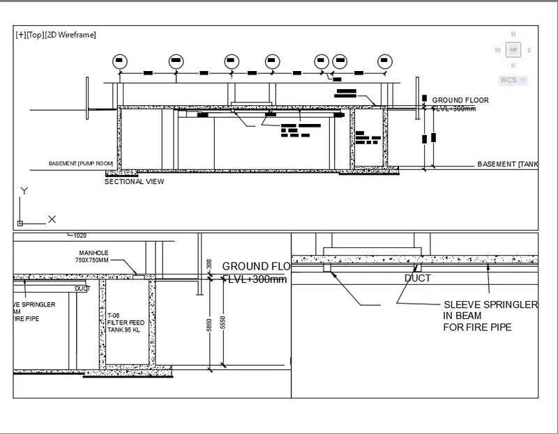
scaling to size to model space to 1:100
as shown in fig below.
STEP 2
After setting layout
press ctrl+P to print the page in the setup as per size in the PDF
to take prinout as per the size.
this prinout layout is set to A1 the page is setup to layout A4 size.
how the dialog box is shown below for the printer setup.
STEP 3
after the page setup
in the preview option you can see how the layout is came.
after setting is done the files will save to PDF to the size.
save the in the folder
RESULT . The following plot is set to layout using templates is completed.